EP2440751B1 - Abwärmerückgewinnungssystem - Google Patents
Abwärmerückgewinnungssystem Download PDFInfo
- Publication number
- EP2440751B1 EP2440751B1 EP10785816.9A EP10785816A EP2440751B1 EP 2440751 B1 EP2440751 B1 EP 2440751B1 EP 10785816 A EP10785816 A EP 10785816A EP 2440751 B1 EP2440751 B1 EP 2440751B1
- Authority
- EP
- European Patent Office
- Prior art keywords
- fluid
- organic motive
- stage
- thermal resource
- motive fluid
- Prior art date
- Legal status (The legal status is an assumption and is not a legal conclusion. Google has not performed a legal analysis and makes no representation as to the accuracy of the status listed.)
- Active
Links
Images


Classifications
-
- F—MECHANICAL ENGINEERING; LIGHTING; HEATING; WEAPONS; BLASTING
- F01—MACHINES OR ENGINES IN GENERAL; ENGINE PLANTS IN GENERAL; STEAM ENGINES
- F01K—STEAM ENGINE PLANTS; STEAM ACCUMULATORS; ENGINE PLANTS NOT OTHERWISE PROVIDED FOR; ENGINES USING SPECIAL WORKING FLUIDS OR CYCLES
- F01K23/00—Plants characterised by more than one engine delivering power external to the plant, the engines being driven by different fluids
- F01K23/02—Plants characterised by more than one engine delivering power external to the plant, the engines being driven by different fluids the engine cycles being thermally coupled
- F01K23/04—Plants characterised by more than one engine delivering power external to the plant, the engines being driven by different fluids the engine cycles being thermally coupled condensation heat from one cycle heating the fluid in another cycle
-
- F—MECHANICAL ENGINEERING; LIGHTING; HEATING; WEAPONS; BLASTING
- F01—MACHINES OR ENGINES IN GENERAL; ENGINE PLANTS IN GENERAL; STEAM ENGINES
- F01K—STEAM ENGINE PLANTS; STEAM ACCUMULATORS; ENGINE PLANTS NOT OTHERWISE PROVIDED FOR; ENGINES USING SPECIAL WORKING FLUIDS OR CYCLES
- F01K23/00—Plants characterised by more than one engine delivering power external to the plant, the engines being driven by different fluids
- F01K23/02—Plants characterised by more than one engine delivering power external to the plant, the engines being driven by different fluids the engine cycles being thermally coupled
- F01K23/06—Plants characterised by more than one engine delivering power external to the plant, the engines being driven by different fluids the engine cycles being thermally coupled combustion heat from one cycle heating the fluid in another cycle
- F01K23/065—Plants characterised by more than one engine delivering power external to the plant, the engines being driven by different fluids the engine cycles being thermally coupled combustion heat from one cycle heating the fluid in another cycle the combustion taking place in an internal combustion piston engine, e.g. a diesel engine
-
- F—MECHANICAL ENGINEERING; LIGHTING; HEATING; WEAPONS; BLASTING
- F01—MACHINES OR ENGINES IN GENERAL; ENGINE PLANTS IN GENERAL; STEAM ENGINES
- F01K—STEAM ENGINE PLANTS; STEAM ACCUMULATORS; ENGINE PLANTS NOT OTHERWISE PROVIDED FOR; ENGINES USING SPECIAL WORKING FLUIDS OR CYCLES
- F01K25/00—Plants or engines characterised by use of special working fluids, not otherwise provided for; Plants operating in closed cycles and not otherwise provided for
- F01K25/08—Plants or engines characterised by use of special working fluids, not otherwise provided for; Plants operating in closed cycles and not otherwise provided for using special vapours
Definitions
- the present invention relates to the field of waste heat recovery systems. More particularly, the invention relates to a water based-organic motive fluid waste heat recovery system.
- ORC organic Rankine cycle
- the present invention provides a waste heat recovery system by which the danger of ignition of the organic motive fluid is virtually prevented.
- WO-A-2009/045196 discloses a cascaded ORC using two waste heat sources from a positive displacement engine.
- US-2009/000299 discloses a waste heat recovery system including at least two integrated rankine cycle systems coupled to at least two separate heat sources having different temperatures.
- EP1,174,590 discloses a system for producing power from a heat source, including intermediate fuid vaporizer, organic fluid vaporizer, organic vapor turbine and organic fluid condenser.
- FR797,473 discloses a heat recovery system using heavy hydrocarbons.
- the present invention provides a waste heat recovery system in accordance with claim 1
- a "high grade waste heat thermal resource fluid” is waste heat generated by an internal combustion engine at a temperature greater than about 250° C.
- the internal combustion engine can be a stationary natural gas or diesel engine and the high grade thermal resource fluid can comprise exhaust gases resulting from a combustion process.
- a "low grade waste heat thermal resource fluid” can be waste heat generated by an internal combustion engine at a temperature less than about 200° C.
- the low grade thermal resource fluid can be jacket water used for cooling the internal combustion engine or an intercooler discharge that was brought in heat exchange relation with a supercharger or turbocharger intake charge delivered to the internal combustion engine or a combination of both the low grade source fluids.
- the low grade waste heat thermal resource fluid has until now been exhausted to the atmosphere.
- the thermal efficiency of the waste heat recovery system of the present invention is significantly improved with respect to prior art systems by exploiting the low grade waste heat thermal resource fluid.
- the discharge of the intermediate fluid from the first turbine can be brought in heat exchange relation with the preheated organic motive fluid at a condenser-vaporizer unit (CVU) wherein the organic motive fluid is vaporized and the intermediate fluid is condensed.
- CVU condenser-vaporizer unit
- the condensed intermediate fluid is brought in heat exchange relation with the high grade thermal resource fluid at a boiler and is vaporized thereby.
- the intermediate fluid can be water and the boiler can be a steam generator. Since usually water is used to extract heat from the high grade thermal resource fluid and the extracted heat is transferred to the organic motive fluid by means of the CVU, a limited increase in temperature is provided and the danger that the organic motive fluid will be ignited is virtually overcome.
- the discharge of the organic motive fluid from the second turbine is delivered to a condenser, and condensed organic motive fluid is delivered by a condensate pump to a preheater to which the low grade thermal resource fluid is also supplied for preheating the condensed organic motive fluid.
- the heat transfer rate of the organic motive fluid and of the low grade thermal resource fluid within the preheater is virtually matched, thereby resulting in a high thermal efficiency of the heat transfer system.
- the condensed organic motive fluid is delivered by the condensate pump to first and second stage preheaters, the low grade thermal resource fluid being supplied to one of the first and second stage preheaters.
- the condensed organic motive fluid is preheated at the first stage preheater by means of condensed intermediate fluid exiting the CVU and is preheated at the second stage preheater by means of the low grade thermal resource fluid.
- the boiler comprises a first stage boiler and a second stage boiler.
- the condensed intermediate fluid exits the CVU via first and second conduits extending to the first and second stage boilers, respectively, the high grade thermal resource fluid exiting the internal combustion engine being delivered to the first stage boiler to generate high pressure intermediate fluid for supply to the first turbine and the high grade thermal resource fluid exiting the first stage boiler being supplied to the second stage boiler to generate low pressure intermediate fluid for supply to the CVU.
- the present invention is a waste heat recovery system by which two different waste heat thermal resources that are usually derived from an internal combustion engine and are normally not exploited are used to transfer heat to an organic Rankine cycle (ORC) to produce power.
- ORC organic Rankine cycle
- Similar systems having two turbines, and using, without limitation, water, an alcohol, ethane, propane, butane, iso-butane, n-pentane, isopentane, hexane, iso-hexane and mixtures thereof, etc. as working fluids or motive fluid have been described in U.S. patent application Ser. No. 12/457,477 .
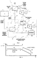
- FIG. 1 schematically illustrates a waste heat recovery system, which is designated by numeral 10.
- Waste heat recovery system 10 comprises an internal combustion engine (IC) 5 which usually provides two different thermal resources, a topping steam turbine cycle (STC) 20 heated by fluid from at least one of the thermal resources, and an ORC circuit 40 heated by STC 20.
- IC internal combustion engine
- STC topping steam turbine cycle
- ORC circuit 40 heated by STC 20.
- IC 5 e.g. a stationary natural gas or diesel engine, etc. uses one or more positive displacement devices such as pistons to provide effective and efficient operation, while being associated with a relatively high efficiency, a relatively low cost, high mechanical efficiency, and wide variation in speed and load.
- IC 5 generates two different waste heat resource fluids: a high grade thermal resource fluid in the form of exhaust gases at a temperature ranging from usually 250-500°C supplied through line 7 to steam generator 15, e.g. a heat exchanger, and usually discharged thereafter to the atmosphere; and a low grade thermal resource fluid in the form of engine jacket water for cooling IC 5 supplied through conduit 21 at a temperature ranging from 80-110°C, and typically from 95-103°C, to ORC circuit 40.
- Engine jacket water which is circulated in a closed circuit via conduits 21 and 22 by means of a dedicated water pump (not shown) associated with IC 5, is a thermal resource fluid that has not been fully exploited heretofore in prior art waste recovery systems.
- engine jacket water is used to cool the cylinder head and block of IC 5, and the heated jacket water has been cooled heretofore by a radiator such that the waste heat generated thereby has been discharged to the atmosphere.
- System 10 therefore advantageously utilizes this thermal resource fluid by supplying the jacket water via conduit 21 to preheater 42 of ORC 40, in order to preheat the organic motive fluid and to increase the thermal efficiency of system 10.
- the heat depleted jacket water exiting preheater 42 is then recirculated to IC 5 via conduit 22.
- topping STC 20 condensate is supplied by pump 24 via lines 16 and 17 to steam generator 15, and is brought in heat transfer relation with the exhaust gases discharged from IC 5, thereby generating high pressure steam.
- the high pressure steam is delivered to steam turbine 29 via line 26.
- the steam is expanded in turbine 29, generating electricity by means of generator 31 coupled to turbine 29.
- Low pressure steam discharged from turbine 29 is delivered to condenser-vaporizer unit (CVU) 35 via line 32, and is condensed thereby.
- CVU condenser-vaporizer unit
- organic motive fluid is preheated in preheater 42 by the engine jacket water.
- the preheated organic motive fluid is supplied by line 36 from preheater 42 to CVU 35, and is vaporized by the low pressure steam therein.
- the vaporized organic motive fluid is then supplied via line 37 to organic vapor turbine 45 to produce power, such as by generating electricity by means of electric generator 47 coupled to turbine 45.
- the organic motive fluid exhausted from turbine 45 is supplied via line 48 to condenser 52, e.g. an air cooled or water cooled condenser.
- Cycle pump 54 supplies the condensed organic motive fluid via lines 56 and 57 to preheater 42. Since heat is extracted from the exhaust gases of IC 5 by means of STC 20 and is transferred to the organic motive fluid by means of CVU 35, the danger that the organic motive fluid will be ignited is virtually overcome.
- the organic motive fluid may be isobutane, which has a relatively low boiling temperature, allowing system 10 to exploit the relatively low temperature of the jacket water by sufficiently preheating the organic motive fluid so that the heat influx supplied by the low pressure steam exhausted from steam turbine 29 in CVU 35 vaporizes the organic motive fluid thus achieving a relatively high preheating to vaporization heat ratio for the organic motive fluid.
- organic motive fluids including pentane, n-pentane, isopentane, n-butane, hexane, n-hexane, and isohexane, etc.
- Fig. 2 illustrates a temperature (T)/ heat (Q) diagram of the waste heat recovery system of the present invention.
- the organic motive fluid is shown to be preheated in e.g. preheater 42 in Fig. 1 from the condenser temperature at point A to point B, as represented by inclined line 61, primarily by means of the jacket water, which releases its heat within the preheater from point F to point G, as represented by inclined line 65.
- the organic motive fluid, as represented by line 62 is vaporized in CVU 35 in Fig. 1 from point B to point C while the low pressure steam is being condensed, as represented by line 63, from D to E.
- waste heat recovery system 70 comprises a second stage steam generator 75, for extracting heat from the internal combustion exhaust gases exiting first stage steam generator 15.
- System 70 is identical to system 10 of Fig. 1 , with the addition of second stage steam generator 75.
- the steam derived condensate produced by CVU 35 is branched into two lines: line 16 leading to first stage steam generator 15 and line 76 leading to second stage steam generator 75.
- Pump 24 delivers the condensate flowing in conduit 16 to first stage steam generator 15 to produce high pressure steam by means of the exhaust gases exiting IC 5, and the heat depleted exhaust gases exiting first stage steam generator 15 are supplied to second stage steam generator 75 via line 74.
- Pump 78 supplies the steam condensate flowing in conduit 76 to second stage steam generator 75 to produce low pressure steam by means of the heat depleted exhaust gases discharged from first stage steam generator 15.
- the generated low pressure steam exiting second stage steam generator 75 flows in line 81 and is mixed with the low pressure steam discharged from steam turbine 29 prior to being supplied to CVU 35.
- the rate of heat transfer to the organic motive fluid at CVU 35 is increased by increasing the mass flow rate of low pressure steam being introduced to CVU 35.
- not all of the jacket water has to be used in the organic motive fluid preheater.
- the two different waste heat thermal resource fluids provided by an internal combustion engine may have different forms.
- the internal combustion engine may be e.g. a diesel engine 85, which produces exhaust gases flowing through conduit 7 for generating high pressure steam as described hereinabove, as well as an intercooler discharge flowing through conduit 89.
- the intercooler may be configured as an air to air intercooler.
- the compressed and heated air produced by a turbocharger or supercharger, the performance of which is less effective if the compressed air is not cooled, is passed through the intercooler before being introduced to IC 85.
- Organic motive fluid is brought into heat exchanger relation with the intake charge, being discharged through conduit 89, in preheater 42 in order to preheat the condensed organic motive fluid delivered thereto.
- the intercooler discharge is typically at a temperature ranging from 90-100°C, and may attain a temperature of up to approximately 200°C, depending on the type of engine and intercooler.
- the preheated organic motive fluid exits via conduit 36, and the heat depleted intercooler discharge is supplied to IC 5.
- Fig. 5 illustrates a waste recovery system 100 by which the heat influx to the organic motive fluid is increased by employing two preheaters.
- the organic motive fluid circulating in circuit 111 is expanded within organic turbine 45 to produce power and is then condensed in condenser 105, e.g. an air-cooled condenser being cooled by means of blower 94
- the condensed organic motive fluid is supplied by means of cycle pump 97 to first stage preheater 107.
- first stage preheater 107 the organic motive fluid is brought into heat exchanger relation with the steam condensate exiting CVU 35, which is operable to produce a relatively high-temperature condensate of about 80-95°C, e.g.
- the preheated organic motive fluid is additionally heated at second stage preheater 109 by engine jacket water 91 from the internal combustion engine so as to achieve an even higher temperature and is then vaporized in CVU 35 by the low pressure steam discharged from steam turbine 29.
- the preheated organic motive fluid may be additionally heated at second stage preheater 109 by means of an intercooler discharge.
- Water indicated by the dashed line and flows within circuit 114, is vaporized within steam generator 125 while flowing in counterflow fashion with respect to the combustion gases 112, which are exhausted from the internal combustion engine, indicated by the dotted line, and flow within circuit 116.
- the heat depleted steam condensate exiting first stage preheater 107 is supplied by feedwater pump 101 to steam generator 125 and the steam produced, is expanded within steam turbine 29 to produce power.
- Steam generator 125 may comprise economizer 102, evaporator 103, and superheater 104.
- economizer 102 the heat depleted steam condensate delivered by feedwater pump 101 extracts heat from the relatively low temperature combustion gases that exit evaporator 103, in order to increase the feedwater temperature.
- the temperature of the feedwater exiting first stage preheater 107 is maintained above the dew-point temperature of combustion gases 112, to prevent corrosion within economizer 102.
- the heated feedwater is then vaporized at evaporator 103, and the temperature of the vaporized steam is increased by means of superheater 104 prior to being introduced to steam turbine 29.
- superheater 104 the vaporized steam is exposed to the maximum temperature of the combustion gases exiting the internal combustion engine. The amount of heat remaining in the combustion gases exiting superheater 104 is sufficient to vaporize water at evaporator 103.
- the ORC power cycle in the above described embodiment of the present invention can include a recuperator for recuperating heat present in the organic fluid vapors exiting the organic vapor turbines by heating organic motive fluid condensate.
- both the steam turbine and organic vapor turbine can drive a common electric generator which can be optionally interposed between the steam turbine and organic vapor turbine.
Landscapes
- Engineering & Computer Science (AREA)
- Chemical & Material Sciences (AREA)
- Combustion & Propulsion (AREA)
- Mechanical Engineering (AREA)
- General Engineering & Computer Science (AREA)
- Engine Equipment That Uses Special Cycles (AREA)
Claims (11)
- Abwärmerückgewinnungssystem, Folgendes beinhaltend:a) einen Verbrennungsmotor (5) zum Liefern eines hochgradigen thermischen Abwärme-Ressourcenfluids und eines niedriggradigen thermischen Abwärme-Ressourcenfluids;b) einen thermischen Zwischenzyklus (20), welcher geeignet ist, um Wasser als ein Zwischenfluid mithilfe des hochgradigen thermischen Abwärme-Ressourcenfluids zu verdampfen und das Zwischenfluid innerhalb einer ersten Turbine (29) zu expandieren um hierdurch Strom zu erzeugen; undc) einen organischen thermischen Zyklus (40), welcher geeignet ist zum:Vorwärmen eines organischen Antriebsfluids mithilfe des niedriggradigen thermischen Abwärme-Ressourcenfluids;Verdampfen des organischen Antriebsfluids mithilfe des Ablaufs des Zwischenfluids aus der ersten Turbine (29), undExpandieren des verdampften organischen Antriebsfluids in einer zweiten Turbine (45), wodurch Strom erzeugt wird;d) eine kombinierte Kondensator-Verdampfer-Einheit (CVU (35)) zum Verdampfen des organischen Antriebsfluids und zum Kondensieren des Zwischenfluids, wobei die CVU (35) so angeordnet ist, dass das Zwischenfluid aus der ersten Turbine (29) in Wärmetauschbeziehung mit dem vorgewärmten organischen Antriebsfluids gebracht wird;
wobei das System so angeordnet ist, dass das kondensierte Zwischenfluid in Wärmetauscherbeziehung mit dem hochgradigen thermischen Ressourcenfluid in einem Heizkessel (15, 75) gebracht und hierbei verdampft wird, um Dampf zu erzeugen;
wobei der Heizkessel eine erste Heizkesselstufe (15) und eine zweite Heizkesselstufe (75) beinhaltet; und
wobei das System so angeordnet ist, dass das kondensierte Zwischenfluid aus der CVU (35) über eine erste und eine zweite Leitung (16, 76) austritt, welche sich jeweils zur ersten Heizkesselstufe und zur zweiten Heizkesselstufe (15, 75) erstrecken, wobei das hochgradige thermische Ressourcenfluid, welches den Verbrennungsmotor (5) verlässt, an die erste Heizkesselstufe (15) abgegeben wird, um Hochdruck-Zwischenfluid zur Lieferung an die erste Turbine (29) zu erzeugen, und das hochgradige thermische Ressourcenfluid, welches die erste Heizkesselstufe (15) verlässt, an die zweite Heizkesselstufe (75) abgegeben wird, um Niederdruck-Zwischenfluid zur Lieferung an die CVU (35) zu erzeugen. - System nach Anspruch 1 oder 2, wobei das System so angeordnet ist, dass ein Ablauf des organischen Antriebsfluids von der zweiten Turbine (45) an einen Kondensator (52) abgegeben wird, und kondensiertes organisches Antriebsfluid durch eine Umlaufpumpe (54) an einen Vorwärmer (42) abgegeben wird, an welchen ebenfalls das niedriggradige thermische Ressourcenfluid zum Vorwärmen des kondensierten organischen Antriebsfluids abgegeben wird.
- System nach Anspruch 2, welches so angeordnet ist, dass die Wärmeübertragung in der kombinierten Kondensator-Verdampfer-Einheit (CVU (35)) von dem Zwischenfluid an das organische Antriebsfluid nahezu isothermisch ausgeführt wird, während die Wärmeübertragung beim Vorwärmen des kondensierten organischen Antriebsfluids ausgeführt wird, indem im Wesentlichen nur Abwärme von dem niedriggradigen thermischen Ressourcenfluid an das kondensierte organische Antriebsfluid übertragen wird.
- System nach Anspruch 2, welches so angeordnet ist, dass das kondensierte organische Antriebsfluid durch die Umlaufpumpe (54) an eine erste und eine zweite Vorwärmerstufe (107, 109) abgegeben wird, wobei das niedriggradige thermische Ressourcenfluid an eine der ersten und der zweiten Vorwärmerstufe (107, 109) abgegeben wird.
- System nach Anspruch 4, welches so angeordnet ist, dass das dass das kondensierte organische Antriebsfluid in der ersten Vorwärmerstufe (107) mithilfe von kondensiertem Zwischenfluid, welches die CVU (35) verlässt, vorgewärmt wird und in der zweiten Vorwärmerstufe (109) mithilfe des niedriggradigen thermischen Ressourcenfluids vorgewärmt wird.
- System nach einem der vorhergehenden Ansprüche, bei welchem die erste und die zweite Heizkesselstufe (15, 75) Dampferzeuger sind.
- System nach einem der vorhergehenden Ansprüche, bei welchem der Verbrennungsmotor (5) ein stationärer Erdgas- oder Dieselmotor ist und das hochgradige thermische Ressourcenfluid Abgase beinhaltet, welche aus einem Verbrennungsprozess stammen.
- System nach einem der vorhergehenden Ansprüche, bei welchem das niedriggradige thermische Ressourcenfluid Mantelwasser ist, welches zum Kühlen eines Verbrennungsmotors (5) verwendet wird.
- System nach einem der vorhergehenden Ansprüche, bei welchem das niedriggradige thermische Ressourcenfluid ein Ablauf eines Zwischenkühlers ist, welcher in Wärmetauscherbeziehung mit einer an den Verbrennungsmotor (5) abgegebenen Ansaugladung eines Laders oder Turboladers gebracht wurde.
- System nach Anspruch 6, bei welchem der Dampferzeuger einen Economiser, einen Verdampfer und einen Überhitzer beinhaltet, durch welchen Speisewasser sequenziell im Gegenstrom in Bezug auf das hochgradige thermische Ressourcenfluid eingeleitet wird.
- System nach einem der vorhergehenden Ansprüche, bei welchem das organische Antriebsfluid aus der Gruppe gewählt ist, bestehend aus Pentan, n-Pentan, Isopentan, Butan, n-Butan, Isobutan, Hexan, n-Hexan und Isohexan.
Applications Claiming Priority (3)
| Application Number | Priority Date | Filing Date | Title |
|---|---|---|---|
| US12/457,477 US8438849B2 (en) | 2007-04-17 | 2009-06-11 | Multi-level organic rankine cycle power system |
| US12/647,216 US8850814B2 (en) | 2009-06-11 | 2009-12-24 | Waste heat recovery system |
| PCT/IB2010/001393 WO2010143049A2 (en) | 2009-06-11 | 2010-06-09 | Waste heat recovery system |
Publications (3)
| Publication Number | Publication Date |
|---|---|
| EP2440751A2 EP2440751A2 (de) | 2012-04-18 |
| EP2440751A4 EP2440751A4 (de) | 2013-01-23 |
| EP2440751B1 true EP2440751B1 (de) | 2019-11-20 |
Family
ID=43305183
Family Applications (1)
| Application Number | Title | Priority Date | Filing Date |
|---|---|---|---|
| EP10785816.9A Active EP2440751B1 (de) | 2009-06-11 | 2010-06-09 | Abwärmerückgewinnungssystem |
Country Status (4)
| Country | Link |
|---|---|
| US (1) | US8850814B2 (de) |
| EP (1) | EP2440751B1 (de) |
| WO (1) | WO2010143049A2 (de) |
| ZA (1) | ZA201200213B (de) |
Families Citing this family (30)
| Publication number | Priority date | Publication date | Assignee | Title |
|---|---|---|---|---|
| USRE46316E1 (en) * | 2007-04-17 | 2017-02-21 | Ormat Technologies, Inc. | Multi-level organic rankine cycle power system |
| US8236093B2 (en) * | 2009-09-16 | 2012-08-07 | Bha Group, Inc. | Power plant emissions control using integrated organic rankine cycle |
| CA2863530C (en) * | 2011-02-07 | 2020-03-10 | Krishna Moorthy PALANISAMY | Method and apparatus of producing and utilizing thermal energy in a combined heat and power plant |
| US8601814B2 (en) | 2011-04-18 | 2013-12-10 | Ormat Technologies Inc. | Geothermal binary cycle power plant with geothermal steam condensate recovery system |
| US9322300B2 (en) | 2012-07-24 | 2016-04-26 | Access Energy Llc | Thermal cycle energy and pumping recovery system |
| EP2895708B1 (de) * | 2012-08-03 | 2017-05-10 | Tri-o-gen Group B.V. | System zur erholung durch einen organischen rankine-kreislauf mit energie aus mehreren wärmequellen |
| FI20126065L (fi) | 2012-10-11 | 2013-12-02 | Waertsilae Finland Oy | Jäähdytysjärjestely kombimäntämoottorivoimalaitosta varten |
| US9540961B2 (en) * | 2013-04-25 | 2017-01-10 | Access Energy Llc | Heat sources for thermal cycles |
| DE102014016997A1 (de) * | 2014-11-18 | 2016-05-19 | Klaus-Peter Priebe | Mehrstufiges Verfahren zur Nutzung von zwei und mehr Wärmequellen zum Betrieb einer ein- oder mehrstufigen Arbeitsmaschine, Vorwärmung RL-Motorkühlung |
| CN104929806A (zh) * | 2015-06-09 | 2015-09-23 | 同济大学 | 带有机朗肯循环余热回收发电的燃气内燃机热电联产系统 |
| CN105003351B (zh) * | 2015-07-21 | 2016-08-17 | 天津大学 | 对气体机余热能进行梯级回收的多能量形式输出的能源塔 |
| AT516615B1 (de) * | 2015-08-28 | 2016-07-15 | Avl List Gmbh | Verfahren zur Erkennung einer undichten Stelle in einem Wärmerückgewinnungssystem einer Brennkraftmaschine |
| KR102149133B1 (ko) * | 2015-09-24 | 2020-08-28 | 미쓰비시주코마린마시나리 가부시키가이샤 | 배열 회수 장치, 내연 기관 시스템과 선박 및 배열 회수 방법 |
| CA3001915C (en) * | 2015-10-12 | 2023-09-26 | XDI Holdings, LLC | Direct steam generation, electrical power generator, system, apparatus, and method |
| DE112015007098T5 (de) | 2015-12-21 | 2018-08-02 | Cummins Inc. | Integriertes steuersystem zur motorabwärmerückgewinnung mithilfe eines organic-rankine-cycle |
| EP3405657B1 (de) | 2016-01-20 | 2019-11-13 | Climeon AB | Wärmerückgewinnungssystem und verfahren mit verwendung des wärmerückgewinnungssystems zur umwandlung von wärme in elektrische energie |
| CN106224033A (zh) * | 2016-08-31 | 2016-12-14 | 中冶节能环保有限责任公司 | 一种利用钢渣有压热闷过程所产蒸汽发电的工艺方法和装置 |
| US12312981B2 (en) | 2021-04-02 | 2025-05-27 | Ice Thermal Harvesting, Llc | Systems and methods utilizing gas temperature as a power source |
| US11280322B1 (en) | 2021-04-02 | 2022-03-22 | Ice Thermal Harvesting, Llc | Systems for generating geothermal power in an organic Rankine cycle operation during hydrocarbon production based on wellhead fluid temperature |
| US11421663B1 (en) | 2021-04-02 | 2022-08-23 | Ice Thermal Harvesting, Llc | Systems and methods for generation of electrical power in an organic Rankine cycle operation |
| US11326550B1 (en) | 2021-04-02 | 2022-05-10 | Ice Thermal Harvesting, Llc | Systems and methods utilizing gas temperature as a power source |
| US11293414B1 (en) | 2021-04-02 | 2022-04-05 | Ice Thermal Harvesting, Llc | Systems and methods for generation of electrical power in an organic rankine cycle operation |
| US11644015B2 (en) | 2021-04-02 | 2023-05-09 | Ice Thermal Harvesting, Llc | Systems and methods for generation of electrical power at a drilling rig |
| US11486370B2 (en) | 2021-04-02 | 2022-11-01 | Ice Thermal Harvesting, Llc | Modular mobile heat generation unit for generation of geothermal power in organic Rankine cycle operations |
| US11493029B2 (en) | 2021-04-02 | 2022-11-08 | Ice Thermal Harvesting, Llc | Systems and methods for generation of electrical power at a drilling rig |
| US11480074B1 (en) | 2021-04-02 | 2022-10-25 | Ice Thermal Harvesting, Llc | Systems and methods utilizing gas temperature as a power source |
| US11592009B2 (en) | 2021-04-02 | 2023-02-28 | Ice Thermal Harvesting, Llc | Systems and methods for generation of electrical power at a drilling rig |
| DE102022103298A1 (de) * | 2022-02-11 | 2023-08-17 | Jasper Häger | Verfahren und verbesserte Vorrichtung zum Umwandeln von Wärmeenergie in kinetische Energie |
| US12534990B2 (en) | 2022-12-29 | 2026-01-27 | Ice Thermal Harvesting, Llc | Power generation assemblies for hydraulic fracturing systems and methods |
| US12180861B1 (en) | 2022-12-30 | 2024-12-31 | Ice Thermal Harvesting, Llc | Systems and methods to utilize heat carriers in conversion of thermal energy |
Family Cites Families (24)
| Publication number | Priority date | Publication date | Assignee | Title |
|---|---|---|---|---|
| FR797473A (fr) * | 1934-11-12 | 1936-04-27 | Machine thermique à gaz lourd d'hydrogène carburé comme butane, propane, pentane et autres | |
| US3350876A (en) * | 1966-01-19 | 1967-11-07 | Roy W P Johnson | Internal combustion engine plant |
| US3830062A (en) * | 1973-10-09 | 1974-08-20 | Thermo Electron Corp | Rankine cycle bottoming plant |
| US4351155A (en) * | 1980-11-07 | 1982-09-28 | Anderson Forest L | Waste heat recovery system for an internal combustion engine |
| US4586338A (en) * | 1984-11-14 | 1986-05-06 | Caterpillar Tractor Co. | Heat recovery system including a dual pressure turbine |
| SE502492C2 (sv) * | 1991-12-23 | 1995-10-30 | Abb Carbon Ab | Pannanläggning med gemensamt ångsystem |
| US6571548B1 (en) * | 1998-12-31 | 2003-06-03 | Ormat Industries Ltd. | Waste heat recovery in an organic energy converter using an intermediate liquid cycle |
| US6960839B2 (en) * | 2000-07-17 | 2005-11-01 | Ormat Technologies, Inc. | Method of and apparatus for producing power from a heat source |
| CA2425433A1 (en) * | 2000-10-10 | 2003-04-09 | Makoto Uda | Rankine cycle system for internal combustion engine |
| JP2002115505A (ja) * | 2000-10-11 | 2002-04-19 | Honda Motor Co Ltd | 内燃機関のランキンサイクル装置 |
| JP3881872B2 (ja) * | 2001-11-15 | 2007-02-14 | 本田技研工業株式会社 | 内燃機関 |
| US7353653B2 (en) * | 2002-05-22 | 2008-04-08 | Ormat Technologies, Inc. | Hybrid power system for continuous reliable power at locations including remote locations |
| US8061139B2 (en) * | 2002-05-22 | 2011-11-22 | Ormat Technologies, Inc. | Integrated engine generator rankine cycle power system |
| US6883328B2 (en) * | 2002-05-22 | 2005-04-26 | Ormat Technologies, Inc. | Hybrid power system for continuous reliable power at remote locations |
| AT414156B (de) * | 2002-10-11 | 2006-09-15 | Dirk Peter Dipl Ing Claassen | Verfahren und einrichtung zur rückgewinnung von energie |
| DE10307374A1 (de) * | 2003-02-21 | 2004-09-02 | Alstom Technology Ltd | Verfahren zum Betrieb eines teilgeschlossenen, aufgeladenen Gasturbinenkreislaufs sowie Gasturbinensystem zur Durchführung des Verfahrens |
| US7107774B2 (en) * | 2003-08-12 | 2006-09-19 | Washington Group International, Inc. | Method and apparatus for combined cycle power plant operation |
| US7013644B2 (en) * | 2003-11-18 | 2006-03-21 | Utc Power, Llc | Organic rankine cycle system with shared heat exchanger for use with a reciprocating engine |
| US20070095266A1 (en) * | 2005-10-28 | 2007-05-03 | Chevron U.S.A. Inc. | Concrete double-hulled tank ship |
| US7775045B2 (en) | 2005-10-31 | 2010-08-17 | Ormat Technologies, Inc. | Method and system for producing power from a source of steam |
| DE102006043835A1 (de) * | 2006-09-19 | 2008-03-27 | Bayerische Motoren Werke Ag | Wärmetauscheranordnung |
| US7721543B2 (en) * | 2006-10-23 | 2010-05-25 | Southwest Research Institute | System and method for cooling a combustion gas charge |
| US8561405B2 (en) * | 2007-06-29 | 2013-10-22 | General Electric Company | System and method for recovering waste heat |
| EP2212524A4 (de) | 2007-10-04 | 2012-04-18 | United Technologies Corp | Abwärme von einem hubkolbenmotor verwendendes in kaskade geschaltetes organic rankine cycle (orc-)system |
-
2009
- 2009-12-24 US US12/647,216 patent/US8850814B2/en active Active
-
2010
- 2010-06-09 WO PCT/IB2010/001393 patent/WO2010143049A2/en not_active Ceased
- 2010-06-09 EP EP10785816.9A patent/EP2440751B1/de active Active
-
2012
- 2012-01-10 ZA ZA2012/00213A patent/ZA201200213B/en unknown
Non-Patent Citations (1)
| Title |
|---|
| None * |
Also Published As
| Publication number | Publication date |
|---|---|
| EP2440751A4 (de) | 2013-01-23 |
| EP2440751A2 (de) | 2012-04-18 |
| WO2010143049A3 (en) | 2011-02-17 |
| WO2010143049A2 (en) | 2010-12-16 |
| US8850814B2 (en) | 2014-10-07 |
| US20100313565A1 (en) | 2010-12-16 |
| ZA201200213B (en) | 2012-09-26 |
Similar Documents
| Publication | Publication Date | Title |
|---|---|---|
| US8850814B2 (en) | Waste heat recovery system | |
| TW449642B (en) | Method of heating gas turbine fuel in a combined cycle power plant using multi-component flow mixtures | |
| US8438849B2 (en) | Multi-level organic rankine cycle power system | |
| US9790815B2 (en) | Method for operating a thermodynamic cycle, and thermodynamic cycle | |
| EP2397659B1 (de) | Abwärmerückführzyklus mit Doppelkreislauf-Rankine | |
| EP2203630B1 (de) | System zur verwertung von abfallwärme | |
| US20100263380A1 (en) | Cascaded organic rankine cycle (orc) system using waste heat from a reciprocating engine | |
| US20100319346A1 (en) | System for recovering waste heat | |
| CN102834591A (zh) | 废热回收发电装置及具备该装置的船舶 | |
| US20100146974A1 (en) | System for recovering waste heat | |
| JP2018200029A (ja) | 発電システム | |
| JPH0654082B2 (ja) | 熱力学サイクルの遂行方法及びその装置 | |
| JPH07174003A (ja) | エネルギ利用装置における有用なエネルギの発生全体を改善する方法およびその方法を実施する液体冷却熱動力エンジン | |
| Zhang et al. | Thermo-economic analysis and optimization of ICE-ORC systems based on a splitter regulation | |
| US20130047614A1 (en) | High temperature orc system | |
| EP2895708B1 (de) | System zur erholung durch einen organischen rankine-kreislauf mit energie aus mehreren wärmequellen | |
| JP2018021485A (ja) | 多段ランキンサイクルシステム、内燃機関、及び多段ランキンサイクルシステムの運転方法 | |
| JP4509453B2 (ja) | カリナボトミングサイクルを備える統合型ガス化複合サイクル発電プラント | |
| USRE46316E1 (en) | Multi-level organic rankine cycle power system |
Legal Events
| Date | Code | Title | Description |
|---|---|---|---|
| PUAI | Public reference made under article 153(3) epc to a published international application that has entered the european phase |
Free format text: ORIGINAL CODE: 0009012 |
|
| 17P | Request for examination filed |
Effective date: 20120110 |
|
| AK | Designated contracting states |
Kind code of ref document: A2 Designated state(s): AL AT BE BG CH CY CZ DE DK EE ES FI FR GB GR HR HU IE IS IT LI LT LU LV MC MK MT NL NO PL PT RO SE SI SK SM TR |
|
| DAX | Request for extension of the european patent (deleted) | ||
| A4 | Supplementary search report drawn up and despatched |
Effective date: 20130104 |
|
| RIC1 | Information provided on ipc code assigned before grant |
Ipc: F01K 25/08 20060101ALI20121220BHEP Ipc: F01K 23/04 20060101AFI20121220BHEP Ipc: F01K 23/06 20060101ALI20121220BHEP |
|
| 17Q | First examination report despatched |
Effective date: 20160729 |
|
| 17Q | First examination report despatched |
Effective date: 20160824 |
|
| STAA | Information on the status of an ep patent application or granted ep patent |
Free format text: STATUS: EXAMINATION IS IN PROGRESS |
|
| GRAP | Despatch of communication of intention to grant a patent |
Free format text: ORIGINAL CODE: EPIDOSNIGR1 |
|
| STAA | Information on the status of an ep patent application or granted ep patent |
Free format text: STATUS: GRANT OF PATENT IS INTENDED |
|
| INTG | Intention to grant announced |
Effective date: 20190821 |
|
| GRAS | Grant fee paid |
Free format text: ORIGINAL CODE: EPIDOSNIGR3 |
|
| GRAA | (expected) grant |
Free format text: ORIGINAL CODE: 0009210 |
|
| STAA | Information on the status of an ep patent application or granted ep patent |
Free format text: STATUS: THE PATENT HAS BEEN GRANTED |
|
| AK | Designated contracting states |
Kind code of ref document: B1 Designated state(s): AL AT BE BG CH CY CZ DE DK EE ES FI FR GB GR HR HU IE IS IT LI LT LU LV MC MK MT NL NO PL PT RO SE SI SK SM TR |
|
| REG | Reference to a national code |
Ref country code: GB Ref legal event code: FG4D |
|
| REG | Reference to a national code |
Ref country code: CH Ref legal event code: EP |
|
| REG | Reference to a national code |
Ref country code: IE Ref legal event code: FG4D |
|
| REG | Reference to a national code |
Ref country code: DE Ref legal event code: R096 Ref document number: 602010062049 Country of ref document: DE |
|
| REG | Reference to a national code |
Ref country code: AT Ref legal event code: REF Ref document number: 1204440 Country of ref document: AT Kind code of ref document: T Effective date: 20191215 |
|
| REG | Reference to a national code |
Ref country code: NL Ref legal event code: MP Effective date: 20191120 |
|
| REG | Reference to a national code |
Ref country code: LT Ref legal event code: MG4D |
|
| PG25 | Lapsed in a contracting state [announced via postgrant information from national office to epo] |
Ref country code: ES Free format text: LAPSE BECAUSE OF FAILURE TO SUBMIT A TRANSLATION OF THE DESCRIPTION OR TO PAY THE FEE WITHIN THE PRESCRIBED TIME-LIMIT Effective date: 20191120 Ref country code: GR Free format text: LAPSE BECAUSE OF FAILURE TO SUBMIT A TRANSLATION OF THE DESCRIPTION OR TO PAY THE FEE WITHIN THE PRESCRIBED TIME-LIMIT Effective date: 20200221 Ref country code: NL Free format text: LAPSE BECAUSE OF FAILURE TO SUBMIT A TRANSLATION OF THE DESCRIPTION OR TO PAY THE FEE WITHIN THE PRESCRIBED TIME-LIMIT Effective date: 20191120 Ref country code: BG Free format text: LAPSE BECAUSE OF FAILURE TO SUBMIT A TRANSLATION OF THE DESCRIPTION OR TO PAY THE FEE WITHIN THE PRESCRIBED TIME-LIMIT Effective date: 20200220 Ref country code: FI Free format text: LAPSE BECAUSE OF FAILURE TO SUBMIT A TRANSLATION OF THE DESCRIPTION OR TO PAY THE FEE WITHIN THE PRESCRIBED TIME-LIMIT Effective date: 20191120 Ref country code: LT Free format text: LAPSE BECAUSE OF FAILURE TO SUBMIT A TRANSLATION OF THE DESCRIPTION OR TO PAY THE FEE WITHIN THE PRESCRIBED TIME-LIMIT Effective date: 20191120 Ref country code: LV Free format text: LAPSE BECAUSE OF FAILURE TO SUBMIT A TRANSLATION OF THE DESCRIPTION OR TO PAY THE FEE WITHIN THE PRESCRIBED TIME-LIMIT Effective date: 20191120 Ref country code: SE Free format text: LAPSE BECAUSE OF FAILURE TO SUBMIT A TRANSLATION OF THE DESCRIPTION OR TO PAY THE FEE WITHIN THE PRESCRIBED TIME-LIMIT Effective date: 20191120 Ref country code: NO Free format text: LAPSE BECAUSE OF FAILURE TO SUBMIT A TRANSLATION OF THE DESCRIPTION OR TO PAY THE FEE WITHIN THE PRESCRIBED TIME-LIMIT Effective date: 20200220 |
|
| PG25 | Lapsed in a contracting state [announced via postgrant information from national office to epo] |
Ref country code: IS Free format text: LAPSE BECAUSE OF FAILURE TO SUBMIT A TRANSLATION OF THE DESCRIPTION OR TO PAY THE FEE WITHIN THE PRESCRIBED TIME-LIMIT Effective date: 20200320 Ref country code: HR Free format text: LAPSE BECAUSE OF FAILURE TO SUBMIT A TRANSLATION OF THE DESCRIPTION OR TO PAY THE FEE WITHIN THE PRESCRIBED TIME-LIMIT Effective date: 20191120 |
|
| PG25 | Lapsed in a contracting state [announced via postgrant information from national office to epo] |
Ref country code: AL Free format text: LAPSE BECAUSE OF FAILURE TO SUBMIT A TRANSLATION OF THE DESCRIPTION OR TO PAY THE FEE WITHIN THE PRESCRIBED TIME-LIMIT Effective date: 20191120 |
|
| PG25 | Lapsed in a contracting state [announced via postgrant information from national office to epo] |
Ref country code: PT Free format text: LAPSE BECAUSE OF FAILURE TO SUBMIT A TRANSLATION OF THE DESCRIPTION OR TO PAY THE FEE WITHIN THE PRESCRIBED TIME-LIMIT Effective date: 20200412 Ref country code: EE Free format text: LAPSE BECAUSE OF FAILURE TO SUBMIT A TRANSLATION OF THE DESCRIPTION OR TO PAY THE FEE WITHIN THE PRESCRIBED TIME-LIMIT Effective date: 20191120 Ref country code: CZ Free format text: LAPSE BECAUSE OF FAILURE TO SUBMIT A TRANSLATION OF THE DESCRIPTION OR TO PAY THE FEE WITHIN THE PRESCRIBED TIME-LIMIT Effective date: 20191120 Ref country code: RO Free format text: LAPSE BECAUSE OF FAILURE TO SUBMIT A TRANSLATION OF THE DESCRIPTION OR TO PAY THE FEE WITHIN THE PRESCRIBED TIME-LIMIT Effective date: 20191120 Ref country code: DK Free format text: LAPSE BECAUSE OF FAILURE TO SUBMIT A TRANSLATION OF THE DESCRIPTION OR TO PAY THE FEE WITHIN THE PRESCRIBED TIME-LIMIT Effective date: 20191120 |
|
| REG | Reference to a national code |
Ref country code: AT Ref legal event code: MK05 Ref document number: 1204440 Country of ref document: AT Kind code of ref document: T Effective date: 20191120 |
|
| REG | Reference to a national code |
Ref country code: DE Ref legal event code: R097 Ref document number: 602010062049 Country of ref document: DE |
|
| PG25 | Lapsed in a contracting state [announced via postgrant information from national office to epo] |
Ref country code: SK Free format text: LAPSE BECAUSE OF FAILURE TO SUBMIT A TRANSLATION OF THE DESCRIPTION OR TO PAY THE FEE WITHIN THE PRESCRIBED TIME-LIMIT Effective date: 20191120 Ref country code: SM Free format text: LAPSE BECAUSE OF FAILURE TO SUBMIT A TRANSLATION OF THE DESCRIPTION OR TO PAY THE FEE WITHIN THE PRESCRIBED TIME-LIMIT Effective date: 20191120 |
|
| PLBE | No opposition filed within time limit |
Free format text: ORIGINAL CODE: 0009261 |
|
| STAA | Information on the status of an ep patent application or granted ep patent |
Free format text: STATUS: NO OPPOSITION FILED WITHIN TIME LIMIT |
|
| 26N | No opposition filed |
Effective date: 20200821 |
|
| PG25 | Lapsed in a contracting state [announced via postgrant information from national office to epo] |
Ref country code: SI Free format text: LAPSE BECAUSE OF FAILURE TO SUBMIT A TRANSLATION OF THE DESCRIPTION OR TO PAY THE FEE WITHIN THE PRESCRIBED TIME-LIMIT Effective date: 20191120 Ref country code: PL Free format text: LAPSE BECAUSE OF FAILURE TO SUBMIT A TRANSLATION OF THE DESCRIPTION OR TO PAY THE FEE WITHIN THE PRESCRIBED TIME-LIMIT Effective date: 20191120 Ref country code: AT Free format text: LAPSE BECAUSE OF FAILURE TO SUBMIT A TRANSLATION OF THE DESCRIPTION OR TO PAY THE FEE WITHIN THE PRESCRIBED TIME-LIMIT Effective date: 20191120 |
|
| REG | Reference to a national code |
Ref country code: DE Ref legal event code: R119 Ref document number: 602010062049 Country of ref document: DE |
|
| PG25 | Lapsed in a contracting state [announced via postgrant information from national office to epo] |
Ref country code: MC Free format text: LAPSE BECAUSE OF FAILURE TO SUBMIT A TRANSLATION OF THE DESCRIPTION OR TO PAY THE FEE WITHIN THE PRESCRIBED TIME-LIMIT Effective date: 20191120 |
|
| REG | Reference to a national code |
Ref country code: CH Ref legal event code: PL |
|
| PG25 | Lapsed in a contracting state [announced via postgrant information from national office to epo] |
Ref country code: LU Free format text: LAPSE BECAUSE OF NON-PAYMENT OF DUE FEES Effective date: 20200609 |
|
| REG | Reference to a national code |
Ref country code: BE Ref legal event code: MM Effective date: 20200630 |
|
| PG25 | Lapsed in a contracting state [announced via postgrant information from national office to epo] |
Ref country code: IE Free format text: LAPSE BECAUSE OF NON-PAYMENT OF DUE FEES Effective date: 20200609 Ref country code: LI Free format text: LAPSE BECAUSE OF NON-PAYMENT OF DUE FEES Effective date: 20200630 Ref country code: CH Free format text: LAPSE BECAUSE OF NON-PAYMENT OF DUE FEES Effective date: 20200630 Ref country code: FR Free format text: LAPSE BECAUSE OF NON-PAYMENT OF DUE FEES Effective date: 20200630 |
|
| PG25 | Lapsed in a contracting state [announced via postgrant information from national office to epo] |
Ref country code: BE Free format text: LAPSE BECAUSE OF NON-PAYMENT OF DUE FEES Effective date: 20200630 Ref country code: DE Free format text: LAPSE BECAUSE OF NON-PAYMENT OF DUE FEES Effective date: 20210101 |
|
| PG25 | Lapsed in a contracting state [announced via postgrant information from national office to epo] |
Ref country code: MT Free format text: LAPSE BECAUSE OF FAILURE TO SUBMIT A TRANSLATION OF THE DESCRIPTION OR TO PAY THE FEE WITHIN THE PRESCRIBED TIME-LIMIT Effective date: 20191120 Ref country code: CY Free format text: LAPSE BECAUSE OF FAILURE TO SUBMIT A TRANSLATION OF THE DESCRIPTION OR TO PAY THE FEE WITHIN THE PRESCRIBED TIME-LIMIT Effective date: 20191120 |
|
| PG25 | Lapsed in a contracting state [announced via postgrant information from national office to epo] |
Ref country code: MK Free format text: LAPSE BECAUSE OF FAILURE TO SUBMIT A TRANSLATION OF THE DESCRIPTION OR TO PAY THE FEE WITHIN THE PRESCRIBED TIME-LIMIT Effective date: 20191120 |
|
| P01 | Opt-out of the competence of the unified patent court (upc) registered |
Effective date: 20230522 |
|
| PGFP | Annual fee paid to national office [announced via postgrant information from national office to epo] |
Ref country code: GB Payment date: 20250401 Year of fee payment: 16 |
|
| PGFP | Annual fee paid to national office [announced via postgrant information from national office to epo] |
Ref country code: IT Payment date: 20250522 Year of fee payment: 16 |
|
| PGFP | Annual fee paid to national office [announced via postgrant information from national office to epo] |
Ref country code: TR Payment date: 20250603 Year of fee payment: 16 |