EP2440904B1 - Verfahren und vorrichtung zum erfassen von verunreinigungen in einem fluid - Google Patents
Verfahren und vorrichtung zum erfassen von verunreinigungen in einem fluid Download PDFInfo
- Publication number
- EP2440904B1 EP2440904B1 EP10724304.0A EP10724304A EP2440904B1 EP 2440904 B1 EP2440904 B1 EP 2440904B1 EP 10724304 A EP10724304 A EP 10724304A EP 2440904 B1 EP2440904 B1 EP 2440904B1
- Authority
- EP
- European Patent Office
- Prior art keywords
- fluid
- valve
- contaminated
- circuit
- contamination
- Prior art date
- Legal status (The legal status is an assumption and is not a legal conclusion. Google has not performed a legal analysis and makes no representation as to the accuracy of the status listed.)
- Not-in-force
Links
- 239000012530 fluid Substances 0.000 title claims description 138
- 239000000356 contaminant Substances 0.000 title claims description 9
- 238000000034 method Methods 0.000 title description 16
- 239000002245 particle Substances 0.000 claims description 59
- 238000011109 contamination Methods 0.000 claims description 39
- 238000002156 mixing Methods 0.000 claims description 37
- 238000001514 detection method Methods 0.000 claims description 25
- 238000004140 cleaning Methods 0.000 claims description 11
- 230000005291 magnetic effect Effects 0.000 claims description 10
- 230000000903 blocking effect Effects 0.000 claims description 4
- 238000002360 preparation method Methods 0.000 claims description 4
- 230000003287 optical effect Effects 0.000 claims 1
- 239000012535 impurity Substances 0.000 description 18
- 239000010731 rolling oil Substances 0.000 description 9
- 238000005259 measurement Methods 0.000 description 8
- 230000001105 regulatory effect Effects 0.000 description 8
- 238000010790 dilution Methods 0.000 description 6
- 239000012895 dilution Substances 0.000 description 6
- 230000005294 ferromagnetic effect Effects 0.000 description 5
- 239000003921 oil Substances 0.000 description 5
- 238000010586 diagram Methods 0.000 description 4
- 238000005096 rolling process Methods 0.000 description 3
- 230000008859 change Effects 0.000 description 2
- 238000007865 diluting Methods 0.000 description 2
- 239000013528 metallic particle Substances 0.000 description 2
- 239000000203 mixture Substances 0.000 description 2
- 230000008569 process Effects 0.000 description 2
- 230000032258 transport Effects 0.000 description 2
- 229910000831 Steel Inorganic materials 0.000 description 1
- 238000009825 accumulation Methods 0.000 description 1
- 230000000712 assembly Effects 0.000 description 1
- 238000000429 assembly Methods 0.000 description 1
- 230000004888 barrier function Effects 0.000 description 1
- 230000008033 biological extinction Effects 0.000 description 1
- 230000003749 cleanliness Effects 0.000 description 1
- 238000009826 distribution Methods 0.000 description 1
- 230000002349 favourable effect Effects 0.000 description 1
- 230000004907 flux Effects 0.000 description 1
- 230000006698 induction Effects 0.000 description 1
- 230000010354 integration Effects 0.000 description 1
- 239000010687 lubricating oil Substances 0.000 description 1
- 235000021184 main course Nutrition 0.000 description 1
- 239000013618 particulate matter Substances 0.000 description 1
- 238000010926 purge Methods 0.000 description 1
- 230000009467 reduction Effects 0.000 description 1
- 238000010992 reflux Methods 0.000 description 1
- 238000000926 separation method Methods 0.000 description 1
- 238000004088 simulation Methods 0.000 description 1
- 239000002893 slag Substances 0.000 description 1
- 239000010959 steel Substances 0.000 description 1
- 238000011144 upstream manufacturing Methods 0.000 description 1
Images


Classifications
-
- G—PHYSICS
- G01—MEASURING; TESTING
- G01N—INVESTIGATING OR ANALYSING MATERIALS BY DETERMINING THEIR CHEMICAL OR PHYSICAL PROPERTIES
- G01N1/00—Sampling; Preparing specimens for investigation
- G01N1/28—Preparing specimens for investigation including physical details of (bio-)chemical methods covered elsewhere, e.g. G01N33/50, C12Q
- G01N1/38—Diluting, dispersing or mixing samples
-
- G—PHYSICS
- G01—MEASURING; TESTING
- G01N—INVESTIGATING OR ANALYSING MATERIALS BY DETERMINING THEIR CHEMICAL OR PHYSICAL PROPERTIES
- G01N15/00—Investigating characteristics of particles; Investigating permeability, pore-volume or surface-area of porous materials
- G01N15/06—Investigating concentration of particle suspensions
-
- G—PHYSICS
- G01—MEASURING; TESTING
- G01N—INVESTIGATING OR ANALYSING MATERIALS BY DETERMINING THEIR CHEMICAL OR PHYSICAL PROPERTIES
- G01N33/00—Investigating or analysing materials by specific methods not covered by groups G01N1/00 - G01N31/00
- G01N33/26—Oils; Viscous liquids; Paints; Inks
- G01N33/28—Oils, i.e. hydrocarbon liquids
- G01N33/2888—Lubricating oil characteristics, e.g. deterioration
-
- G—PHYSICS
- G01—MEASURING; TESTING
- G01N—INVESTIGATING OR ANALYSING MATERIALS BY DETERMINING THEIR CHEMICAL OR PHYSICAL PROPERTIES
- G01N15/00—Investigating characteristics of particles; Investigating permeability, pore-volume or surface-area of porous materials
- G01N15/06—Investigating concentration of particle suspensions
- G01N15/075—Investigating concentration of particle suspensions by optical means
-
- G—PHYSICS
- G01—MEASURING; TESTING
- G01N—INVESTIGATING OR ANALYSING MATERIALS BY DETERMINING THEIR CHEMICAL OR PHYSICAL PROPERTIES
- G01N1/00—Sampling; Preparing specimens for investigation
- G01N1/28—Preparing specimens for investigation including physical details of (bio-)chemical methods covered elsewhere, e.g. G01N33/50, C12Q
- G01N1/38—Diluting, dispersing or mixing samples
- G01N2001/383—Diluting, dispersing or mixing samples collecting and diluting in a flow of liquid
Definitions
- the invention relates to a particle detection method for detecting or detecting contaminants in a fluid according to the preamble of claim 1, and to a particle detection device for carrying out the method according to claim 4.
- Fluids such as in particular lubricating oils or the like, are exposed during operation of equipment or devices a permanent entry of impurities in the form of ferromagnetic particles or other metallic particles or other dirt particles.
- impurities in the form of ferromagnetic particles or other metallic particles or other dirt particles.
- a certain maximum concentration of impurities depending on the application is tolerable for the operation of a system or equipment.
- rolling oils such as those used in the steel and heavy industry application, may be registered large amounts of impurities, the content of which are hardly determinable with sensors according to the prior art.
- a sensor for detecting the content of ferromagnetic particles in a fluid in this case has a main magnetic circuit, which is formed by a permanent magnet.
- the main magnetic circuit has an air gap that can be exposed to the fluid to cause the particles to collect near the air gap.
- the sensor further includes a Hall element depending on the accumulated Impurities detect the change in the magnetic flux.
- a proportional detector signal is obtained from the content of dirt particles in the fluid.
- An auxiliary magnetic circuit with an induction coil is provided to counteract the main magnetic circuit of the permanent magnet, up to a complete extinction of the magnetic field in the air gap. This allows detachment of the particles collected in the air gap.
- the known sensors and measuring methods for determining the contamination of a fluid are unsuitable for heavy dirt entry or entry of metallic particles per se.
- a contamination level indicator is shown. From a hydraulic circuit branched, contaminated fluid is supplied by means of a pump to a filter element. Then, the pressure rise upstream of the filter element is measured. The pressure increase is proportional to the contamination of the fluid with particles. If the filter element is blocked, it is backwashable. It can also be provided several filter elements with which the measurements can be carried out alternately.
- the WO 2007/145529 A1 relates to a fluid analysis system.
- a bypass line the molecular structure of a fluid is analyzed and evaluated with a computing unit.
- the invention is therefore based on the object of specifying a particle detection device and a particle detection method for operating the particle detection device, with which very high concentrations of impurities in a fluid can be determined.
- the degree of contamination in a fluid can be determined.
- the particle density or the degree of contamination of the undiluted fluid is calculated by a control and / or regulating device or a computer unit.
- the basic structure of the two fluids is preferably the same.
- the contaminated and the cleaned fluid are mixed with one another in a mixing device that can be represented both by a container and by a mixing valve.
- a metering circuit that is, a hydraulic system is provided, with which the contaminated fluid is directed to the device for measuring the impurities by means of a first pump or metering pump.
- the metering pump which is provided for the transport of raw-polluted fluid, such as rolling oil, is seen downstream of a first valve V 1 downstream in the fluid direction, which is preferably designed as a 3/2-way valve. Depending on the switching position of this first valve V 1 polluted fluid can either get into the dosing to the container or be forwarded in the direction of a junction of the main hydraulic system.
- the device has a main circuit comprising a second metering pump, the dirty and / or purified fluid to a Sensor promotes.
- a third valve V 3 and a fourth valve V 4 are provided to realize, together with the valves of the metering circuit, a cleaning mode or a mixing mode for cleaned and contaminated fluid. Furthermore, a measurement mode or an emptying mode can be displayed for both circuits.
- a functional combination of metering circuit and main circuit can be effected in such a way that the metering circuit remains in a preparation mode or standby mode and the main circuit is transferred into a cleaning mode for cleaning off the contaminants in front of the sensor.
- the mentioned method according to the invention for detecting impurities in a fluid can now preferably be operated in the following operating modes.
- the first valve V 1 is in its switched-through position so that highly contaminated fluid in the form of the rolling oil is conveyed through the first metering pump in the direction of the connection to the main hydraulic system , wherein the first metering pump per unit time, a large amount of fluid promotes further, so that lines flushed in the main hydraulic system and deposits can be prevented.
- the rolling oil in the scope of its current pollution is thus returned to the main hydraulic system.
- the main circuit thus decoupled from the dosing circuit has a continuous switching position relative to the valve V 2 , so that the measuring device is bypassed.
- the valves V 3 and V 4 are connected in such a way that in the closed circuit fluid is conveyed out of the container through a filter adjoining the valve V 4 and in such a way purified is returned to the container. Also, the delivery rate of the other metering pump per unit time is high.
- the dosing circuit is decoupled from the main circuit as described above and the valve V 2 is held in its blocking position as a bypass valve to thus pass the fluid through the measuring device. Further, the valve V 4 is switched such that the cleaning filter is bypassed. In this measurement mode, the delivery rate of the second metering pump of the main circuit is selected to be small.
- the valve V 1 In the operating mode "mixing” and “dosing” the dosing, which leads to the mixing container, in operation, ie, the valve V 1 is switched so that contaminated fluid of the main hydraulic system enters the container.
- the metered addition takes place either via a timing of the valve V 1 or by a corresponding reduction of the fluid delivery rate per unit time by the first metering pump.
- the further metering pump of the main circuit in turn has a high fluid delivery per unit time and the measuring device in the form of the contamination sensor CS is bypassed again via the switched valve V 2 .
- the valves V 3 and V 4 are switched so that the filter is again bypassed and such that fluid from the valve V 4 is returned directly into the container.
- the pertinent switching position relative to the main circuit also corresponds to the "mixing" of the fluid in the main circuit, in which case the dosing is decoupled by switching the valve V 1 from the container and with high fluid flow rate through the first metering pump again polluted fluid is further promoted in the main hydraulic system ,
- the last-mentioned switching position with decoupled dosing circuit from the main circuit also corresponds to the actual measuring process, ie the measurement analysis to be performed, but in which valve V 2 is blocked, so that fluid is passed through the measuring device in the form of the contamination sensor by means of the further dosing pump with low fluid delivery rate ,
- the device When a desired filling level in the container is exceeded, the device can be operated in an emptying process, in which bypassing the measuring device by means of a switched-through valve V 2 container fluid passes directly through the switched valve V 3 in the connection to the main hydraulic system, wherein the valve V 4th then in his locked position.
- the pertinent emptying can take place until the container again reaches the desired fill level, which can correspond to a minimum fill level in the container.
- a Hall element is used as the sensor element, which is arranged on a designated for the amount of impurities, in particular in the form of ferromagnetic particles collection point.
- the sensor element detects the amount of impurities in the mixed fluid and transmits the output signal to a control and / or regulating device. It may be expedient to store in the control and / or regulating device a table of values which produces a relationship between the degree of dilution of the amount of impurity and the possibly also very non-linear output signal of the sensor element.
- the table of values can be based on empirically determined values.
- a function determined for example, by simulation can be stored, which represents the relationship between the amount of accumulated contamination and the output signal of the sensor, as a function of the degree of dilution of the fluid.
- the control and / or regulating device controls the dosing circuit and the main circuit as a function of the measured values in the combination of the above-described operating modes. It may be advantageous in this context, in particular if metallic / ferromagnetic particles or impurities are to be detected, in the device for measurement the impurities to provide a collection point for the accumulation of the contamination of the fluid in the form of a permanent magnet. This serves to generate a magnetic field at the collection point.
- a coil may be provided to move an element in the manner of an anchor such that the magnetic field strength at the collection point is variable by the movement of the element, in particular so far herabsetzbar that at least a portion of the accumulated contamination is removable from the collection point , in particular of the fluid of the dosing is rinsed off.
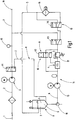
- FIG. 3 is a schematic circuit diagram of an apparatus, generally designated 14, for carrying out a measuring method for detecting impurities in a fluid 1 shown.
- the fluid 1 is in the embodiment shown a rolling oil of a rolling mill or rolling device not shown in detail, which is accordingly highly contaminated and with a very high content of metallic, especially ferromagnetic particles along with other impurities, such as slag, is provided.
- the device 14 essentially consists of a dosing circuit 11 and of a main circuit 12.
- the metering circuit 11 has a first metering pump 3 with a stepping motor drive.
- the first metering pump 3 delivers polluted fluid 2 with particles.
- the first valve V 1 is designed as a 3/2-way valve and in its passage position in Fig. 1 shown, in which the contaminated fluid 2 is guided via a chip sensor 15 led to a connection 18 of a main hydraulic system, that is therefore supplied in the return of said mill train. Said chip sensor 15 is optional and is not absolutely necessary for the actual function of the measuring and diluting device to be described in more detail.
- a third valve V 3 is also designed as a 3/2-way valve as the first valve V 1 .
- the third valve V 3 is in its in Fig.
- the first valve V 1 shown switching position in a passage position to a fourth valve V 4th
- the first valve V 1 also allows in its other switching position the promotion of contaminated fluid 2 in a container 9, which is part of a mixing device 8, consisting of the container 9 and in the present case of a second valve V 2 , however, for the basic function the device is not necessarily needed.
- the main circuit 12 essentially comprises the container 8, a discharge point 16 for the dosing 11, a second metering pump 13 and a device 4 for measuring the contamination of the fluid 1, wherein the device 4 with a defined mixture of purified fluid 5 in the Container 8 and dirty fluid 2, so a kind of mixed fluid 6, can be charged.
- a so-called contamination sensor CS can be used, as it is for example in the DE 10 2006 005 956.5 is described.
- the resulting contamination sensors CS operate in the manner of particle sensors based on light, ie the particles od after passing through a light barrier or the like. Determined by size and number, so that the closer to be explained dilution aspect of the measurement fluid has increased importance. Only through the aforementioned dilution or deconcentration of the fluid medium according to the invention in the specifiable adjustable frame are the particles to be detected so sporadically present in a random distribution in the fluid that the light-based sensors can even respond.
- a downstream of the device 4 for measuring impurities pressure control valve 17 ensures a bubble-free biased operation of the device 4. Furthermore, an inlet section for the fluid is shown between the second metering pump 13 and the contamination sensor CS in the manner of a loop, the length of any can be specified.
- the second valve V 2 which is designed as a 2/2-way valve, serves as a bypass or mixing valve 10 and thus allows the circumvention of the device 4 and the pressure control valve 17.
- the first, third and fourth valves V 1 , V 3 and V 4 are formed as 3/2-way valves, so that the valve assemblies used in this respect are formed as equal components, which helps to reduce the device overhead, so that the overall device is inexpensive to produce. All valves can preferably be controlled electromagnetically, but this is not shown in detail for the sake of simplicity.
- a computing unit 7 which may be part of a control and / or regulating device or part of the device 4 for measuring the contamination in the fluid, calculates the content of dirt particles determined by the device 4 back to the actual content of dirt particles in the fluid non-mixed fluid 2 with particulate contamination from the main hydraulic system, which in the present embodiment transports the rolling oil of the mill train.
- the rolling oil any other form of more or less heavily contaminated fluid with particle introduction can also be treated by means of the described method and apparatus.
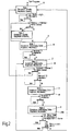
- Fig.2 For example, in the manner of a flow chart, it is one of many modes of operation or methods for detecting contaminants with the in Fig.1 shown device 14 shown.
- mode 1 the dosing circuit 11 is in a standby mode and the main circuit 12 is in a cleaning mode R (cleaning).
- FIG. 3 Another operating situation "cleaning of the oil” is in the Figure 3 clarified and shown in dashed line part is preferably a large amount of fluid by means of the stepper motor drive and the metering pump 3 brought by the working group, for example, to flush the connected lines, which helps prevent deposits, with fluid with current pollution via the connection 18 in the main Hydraulic system is supplied from the input side on.
- the valve V 1 is in its shown through position.
- the main circuit 12 (shown in reinforced solid line) is supplied with purified fluid, which is passed through the filter 19 accordingly.
- the second valve V 2 , the third and the fourth valve V 3 , V 4 in such a switching position shown that the fluid flow generated by the second metering pump 13 past the sensor CS or the device 4 by the third valve V 3 and fourth valve V 4 is guided and insofar can be returned to the container 9 in a closed loop.
- This cycle is repeated until a defined degree of purity for the fluid 5 is reached.
- the stepping motor drive with the second metering pump 13 is operated in the region of large quantities of fluid per unit of time in the main circuit 12.
- the valve V 4 In pure mixing operation for mixing purified fluid 5 with contaminated fluid 2, the valve V 4 is switched such that the filter 19 is then bypassed. Furthermore, it is possible to change to a mode 2 (mode 2) or mixed mode M by mixing cleaned fluid 5 with contaminated fluid 2 in a defined manner, which is largely shown in FIG Figure 4 corresponds to a "mixing and dosing" shows.
- the dosing circuit 11 (shown in dashed lines) changes into a prepared feed mode V, in the dirty fluid 2 of the mixing device 8, here in the form of the container 9, is supplied.
- it has been found to be particularly short to dimension the connecting line between the container 9 and the valve V 1 for example to select less than 10 cm line length.
- the metering pump 3 promotes only a small amount of contaminated fluid 2 per unit time, and instead of a low metering via the pump 3 and the valve V 1 can go into a correspondingly timed operation, in which always in steps certain portion amount is taken from the main line with the rolling oil in the dosing circuit 11.
- the arithmetic unit 7 assumes the pulsed operation for the valve V 1 .
- the third valve V 3 and the fourth valve V 4 are in a switching position shown after the Figure 4 in which the filter 19 has been bypassed in the pertinent mode, so that fluid from the second metering pump 13 is again guided at a high flow rate per unit time to the mixing device 8.
- a mode 3 (mode 3) is switched in which the dosing circuit 11 is in a dirty fluid feed mode Z 2 to the mixing device 8 and the main circuit 12 (again shown in a reinforced solid line) in one Mix mode M remains.
- the switching position of the first valve V 1 is such that polluted fluid 2 is conveyed into the mixing device 8.
- the switching position of the second valve V 2 , the third and fourth valve V 3 , V 4 as again in Fig. 4 such that mixed fluid 6 is moved past the impurity measurement device 4 to the mixing device 8 in the closed circuit.
- the preferred mixing ratios between contaminated fluid 2 and purified fluid 5 are preferred adjusted to between 1: 10 to about 1: 150, ie, for example, that one milliliter of contaminated fluid 2 comes to 10 milliliters of purified fluid 5, wherein for a pertinent admixing of contaminated fluid via the dosing 11 in the container 9 in advance a predetermined amount of purified fluid. 5 already must be.
- the level height in the container 9 in the figures relates to the minimum filling level of the container 9.
- the method changes in the main circuit 12 (again shown in reinforced solid line) in a so-called. Measuring mode MM (Mode 5).
- the dosing circuit 11 in a mode of operation, comparable to the representation of the Fig.2 contaminated fluid is passed directly from the input side to the main hydraulic system via the connection 18.
- the pertinent main course is again shown by dashed lines.
- the second valve V 2 in its blocking position shown and the fourth valve V 4 and the third valve V 3 in its switching position shown, in which mixed fluid 6 is passed through the device 4 for measuring the contamination, but the filter 19 is omitted remains.
- the metering pump 3 in turn promotes per unit time a large amount of fluid and the metering pump 13 a small amount.
- the required measured values are determined in detail as soon as their variance does not exceed a certain limit.
- mode 4 another mode of operation (mode 4) is switched, in which the dosing circuit 11 is brought into the mixing mode M in preparation for supply V and main circuit 12.
- mode 6 mode 6) the dosing circuit 11 is in standby mode.
- the fluid quantity of the main circuit 12 via the connection 18 returned as return to the main hydraulic system. You can then switch back to mode 1 as the operating mode.
- the container 9 together with the emptying point 16 also omitted and the valve V 1 is the output side connected via the dosing circuit 11 directly to the input side of the second metering pump 13.
- the connecting line between the valve V 1 and the metering pump 13 is to be selected short and also a short connection between the output of the second metering pump 13 and the input of the contamination sensor CS is desired.
- the bypass valve or mixing valve V 2 can also be dispensed with, as can the pressure regulating valve 17.
- the chip sensor 15 can also be dispensed with. The required admixture is then, as already explained, via the connection of the metering pump 3 and preferably by a timed operation of the valve V 1 , which then can transfer contaminated fluid 2 in portions into the dosing circuit 11.
- the contaminated fluid with particle pollution controlled by the metering pump 3 controlled directly to the input of the second metering pump 13, which then has on its output side the device 4 for measuring the Verngraphyen, wherein in a branch before the second metering pump 13, this fresh oil from a supply source, such as a barrel, can promote.
- the pertinentschreibstains comes without any valve control and thus without to be controlled valves.
- the fluid thus measured via the contamination sensor CS is then in turn returned to the main hydraulic system, for example in the form of the rolling train.
- an unspecified mixing valve may also occur, which in turn, via the arithmetic unit 7, controls the admixture.
- the measuring and mixing device of the dosing 11 may be connected with a supply directly from the valve V 1 coming before the contamination sensor CS, which helps facilitate integration of the device in any valve blocks.
- the supply line thus ends behind the further metering pump 13 in the fluid path to the sensor CS.
Landscapes
- Chemical & Material Sciences (AREA)
- Health & Medical Sciences (AREA)
- Life Sciences & Earth Sciences (AREA)
- Pathology (AREA)
- Analytical Chemistry (AREA)
- Biochemistry (AREA)
- General Health & Medical Sciences (AREA)
- General Physics & Mathematics (AREA)
- Immunology (AREA)
- Physics & Mathematics (AREA)
- Engineering & Computer Science (AREA)
- Chemical Kinetics & Catalysis (AREA)
- Dispersion Chemistry (AREA)
- General Chemical & Material Sciences (AREA)
- Oil, Petroleum & Natural Gas (AREA)
- Food Science & Technology (AREA)
- Medicinal Chemistry (AREA)
- Sampling And Sample Adjustment (AREA)
- Feeding, Discharge, Calcimining, Fusing, And Gas-Generation Devices (AREA)
- Fluid-Pressure Circuits (AREA)
Applications Claiming Priority (2)
| Application Number | Priority Date | Filing Date | Title |
|---|---|---|---|
| DE102009024561A DE102009024561A1 (de) | 2009-06-08 | 2009-06-08 | Verfahren und Vorrichtung zum Erfassen von Verunreinigungen in einem Fluid |
| PCT/EP2010/003389 WO2010142403A1 (de) | 2009-06-08 | 2010-06-04 | Verfahren und vorrichtung zum erfassen von verunreinigungen in einem fluid |
Publications (2)
| Publication Number | Publication Date |
|---|---|
| EP2440904A1 EP2440904A1 (de) | 2012-04-18 |
| EP2440904B1 true EP2440904B1 (de) | 2018-04-11 |
Family
ID=42711806
Family Applications (1)
| Application Number | Title | Priority Date | Filing Date |
|---|---|---|---|
| EP10724304.0A Not-in-force EP2440904B1 (de) | 2009-06-08 | 2010-06-04 | Verfahren und vorrichtung zum erfassen von verunreinigungen in einem fluid |
Country Status (9)
| Country | Link |
|---|---|
| US (1) | US8875564B2 (pt) |
| EP (1) | EP2440904B1 (pt) |
| JP (1) | JP5662428B2 (pt) |
| CN (1) | CN102460108B (pt) |
| BR (1) | BRPI1013107A2 (pt) |
| DE (1) | DE102009024561A1 (pt) |
| RU (1) | RU2524057C2 (pt) |
| WO (1) | WO2010142403A1 (pt) |
| ZA (1) | ZA201108953B (pt) |
Families Citing this family (10)
| Publication number | Priority date | Publication date | Assignee | Title |
|---|---|---|---|---|
| JP5675570B2 (ja) * | 2011-12-02 | 2015-02-25 | 三菱重工業株式会社 | 潤滑油の劣化評価装置および潤滑油の劣化評価システム |
| CN102562560B (zh) * | 2011-12-16 | 2015-08-05 | 中国航空工业集团公司北京长城航空测控技术研究所 | 一种液压泵磨损的实时检测方法 |
| DE102012016458A1 (de) * | 2012-08-17 | 2014-05-15 | Hydac Filter Systems Gmbh | Vorrichtung zum Feststellen von Partikelverschmutzungen in Fluiden |
| EP3211418A1 (en) * | 2016-02-23 | 2017-08-30 | C.C. Jensen A/S | Liquid condition assessment for a multimode operational system |
| EP3658889B1 (en) * | 2017-07-25 | 2022-07-13 | Koninklijke Philips N.V. | Particle sensor and particle sensing method |
| DE102017008580A1 (de) * | 2017-09-13 | 2019-03-14 | Hydac Filter Sytems Gmbh | Filteraggregat |
| CN109709003B (zh) * | 2017-10-25 | 2021-07-30 | 中国航发商用航空发动机有限责任公司 | 杂质颗粒检测传感器测试装置及方法 |
| CN107831098B (zh) * | 2017-11-07 | 2021-03-26 | 常州杰森智能环境装备有限公司 | 一种粉尘颗粒检测装置 |
| KR102175840B1 (ko) * | 2018-11-05 | 2020-11-06 | 주식회사 포스코 | 냉간 압연의 압연유 농도 계측 시스템 |
| CN116148144B (zh) * | 2023-04-03 | 2025-10-28 | 西安热工研究院有限公司 | 一种在线测量电力用油颗粒度的系统及方法 |
Family Cites Families (28)
| Publication number | Priority date | Publication date | Assignee | Title |
|---|---|---|---|---|
| US3902115A (en) * | 1973-09-26 | 1975-08-26 | Coulter Electronics | Self-cleaning aperture tube for coulter study apparatus and electrolyte supply system therefor |
| US4095472A (en) * | 1977-08-15 | 1978-06-20 | Phillips Petroleum Company | Liquid sample dilution system |
| FR2448746A1 (fr) | 1979-02-08 | 1980-09-05 | Etude Realisa Equip Speciaux | Dispositifs pour maintenir dans un rapport constant les debits instantanes de deux fluides et applications |
| EP0116580B1 (en) * | 1982-08-13 | 1987-12-09 | Secretary of State for Trade and Industry in Her Britannic Majesty's Gov. of the U.K. of Great Britain and Northern Ireland | Contamination level indicator |
| JPS62255849A (ja) | 1986-04-28 | 1987-11-07 | Fuji Heavy Ind Ltd | 粒子測定装置 |
| US4794806A (en) * | 1987-02-13 | 1989-01-03 | Nicoli David F | Automatic dilution system |
| IT1208858B (it) | 1987-03-06 | 1989-07-10 | Iveco Fiat | Particelle di usura nel fluido lu sensore per rilevare il livello di brificante di sistemi di propulsio particelle ferromagnetiche presenti ne di autoveicoli in un fluido particolarmente per rilevare il livello di presenza di |
| US5007297A (en) * | 1988-12-06 | 1991-04-16 | Pacific Scientific Company | Particle size measuring system with automatic dilution of sample |
| US5332512A (en) * | 1991-12-19 | 1994-07-26 | Pacific Scientific Company | Isokinetic diluter for particle measuring instrument |
| AU666749B2 (en) * | 1992-09-21 | 1996-02-22 | Energy Resources Of Australia Ltd | Method of measurement of abnormal wear debris and particulate contamination in machine components by oil analysis |
| US5739916A (en) | 1995-12-04 | 1998-04-14 | University Of Alabama At Huntsville | Apparatus and method for determining the concentration of species in a substance |
| RU2109267C1 (ru) * | 1996-02-15 | 1998-04-20 | Ульяновский государственный технический университет | Устройство для контроля концентрации механических примесей в сож |
| JP3608066B2 (ja) * | 1997-01-14 | 2005-01-05 | 株式会社日立製作所 | 粒子分析装置 |
| US6437563B1 (en) * | 1997-11-21 | 2002-08-20 | Quantum Design, Inc. | Method and apparatus for making measurements of accumulations of magnetically susceptible particles combined with analytes |
| US6007235A (en) * | 1998-02-25 | 1999-12-28 | Honeywell Inc. | Sampling and diluting system for particle size distribution measurement |
| US6211956B1 (en) * | 1998-10-15 | 2001-04-03 | Particle Sizing Systems, Inc. | Automatic dilution system for high-resolution particle size analysis |
| US6582661B1 (en) * | 2000-06-30 | 2003-06-24 | Csi Technology, Inc. | Integrated lubricant analyzer |
| JP2002039935A (ja) | 2000-07-25 | 2002-02-06 | Mitsubishi Kakoki Kaisha Ltd | 油中の粒子測定装置 |
| DE10060609A1 (de) | 2000-12-05 | 2002-09-19 | Zahnradfabrik Friedrichshafen | Verfahren und Einrichtung zur Maschinendiagnose und insbesondere zur Getriebediagnose |
| JP2002250687A (ja) * | 2001-02-22 | 2002-09-06 | Nikkiso Co Ltd | 粒度分布測定システム用廃液処理装置 |
| DE10110156B4 (de) * | 2001-03-02 | 2009-01-02 | Riebel, Ulrich, Prof. Dr.-Ing. | Verfahren zur Verdünnung von Aerosolen bei der Messung der Aerosolkonzentration und Vorrichtung zur Durchführung des Verfahrens |
| AUPR692201A0 (en) * | 2001-08-09 | 2001-08-30 | Commonwealth Scientific And Industrial Research Organisation | Online fluid contaminant detector |
| US6947126B2 (en) * | 2002-03-13 | 2005-09-20 | The Boc Group, Inc. | Dilution apparatus and method of diluting a liquid sample |
| JP4143349B2 (ja) * | 2002-07-22 | 2008-09-03 | 株式会社堀場製作所 | 粒径分布測定方法、粒径分布測定装置および粒径分布測定装置の測定プログラム |
| WO2007077498A1 (en) * | 2006-01-04 | 2007-07-12 | Koninklijke Philips Electronics N. V. | Microelectronic device with magnetic excitation wires |
| DE102006005956A1 (de) | 2006-02-02 | 2007-08-16 | Hydac Filtertechnik Gmbh | Vorrichtung zum Detektieren von Partikeln in einem Fluidstrom, insbesondere induktiver Partikelzähler, sowie zugehöriges System zum Kühlen und/oder Schmieren von Komponenten einer Antriebseinheit |
| NO20062756L (no) | 2006-06-13 | 2007-12-14 | Genesis Applied Technology As | Fluidanalyseringssystem |
| DE202008013327U1 (de) * | 2008-09-29 | 2009-01-29 | Topas Gmbh Technologie-Orientierte Partikel-, Analysen- Und Sensortechnik | Aerosolquellsystem mit Aerosolausströmern für eine gleichmäßige Verteilung von Aerosol eines Aerosolgenerators zu Prüfzwecken in die Umgebung |
-
2009
- 2009-06-08 DE DE102009024561A patent/DE102009024561A1/de not_active Withdrawn
-
2010
- 2010-06-04 JP JP2012514376A patent/JP5662428B2/ja not_active Expired - Fee Related
- 2010-06-04 WO PCT/EP2010/003389 patent/WO2010142403A1/de not_active Ceased
- 2010-06-04 CN CN201080025281.6A patent/CN102460108B/zh not_active Expired - Fee Related
- 2010-06-04 RU RU2011150210/28A patent/RU2524057C2/ru not_active IP Right Cessation
- 2010-06-04 BR BRPI1013107A patent/BRPI1013107A2/pt not_active IP Right Cessation
- 2010-06-04 US US13/322,979 patent/US8875564B2/en not_active Expired - Fee Related
- 2010-06-04 EP EP10724304.0A patent/EP2440904B1/de not_active Not-in-force
-
2011
- 2011-12-06 ZA ZA2011/08953A patent/ZA201108953B/en unknown
Also Published As
| Publication number | Publication date |
|---|---|
| ZA201108953B (en) | 2013-02-27 |
| EP2440904A1 (de) | 2012-04-18 |
| RU2011150210A (ru) | 2013-07-27 |
| DE102009024561A1 (de) | 2010-12-16 |
| WO2010142403A1 (de) | 2010-12-16 |
| BRPI1013107A2 (pt) | 2017-08-15 |
| US8875564B2 (en) | 2014-11-04 |
| US20120103091A1 (en) | 2012-05-03 |
| JP2012529631A (ja) | 2012-11-22 |
| RU2524057C2 (ru) | 2014-07-27 |
| CN102460108B (zh) | 2015-12-02 |
| JP5662428B2 (ja) | 2015-01-28 |
| CN102460108A (zh) | 2012-05-16 |
Similar Documents
| Publication | Publication Date | Title |
|---|---|---|
| EP2440904B1 (de) | Verfahren und vorrichtung zum erfassen von verunreinigungen in einem fluid | |
| WO2013041608A1 (de) | Reinigungsanlage | |
| DE4311477C2 (de) | Differentialrefraktometer | |
| DE112012006422T5 (de) | Reinigungsvorrichtung für eine elektroerosive Bearbeitungsflüssigkeit und Reinigungsverfahren für eine elektroerosive Bearbeitungsflüssigkeit | |
| DE3710682C2 (pt) | ||
| DE102008047404B4 (de) | Einem Partikelzähler vorzuschaltende Einrichtung zur in sich geschlossenen Verdünnung von Aerosolen | |
| DE2515964A1 (de) | Verfahren und vorrichtung zur quantitativen analyse | |
| DE4424909A1 (de) | Verfahren und Vorrichtung zur Ortung von Schadstoffansammlungen | |
| DE3632698A1 (de) | Vorrichtung zur automatischen kalibrierung eines gassensors | |
| EP3156133A1 (de) | Mikroflotationsanlage und verfahren zum betreiben einer mikroflotationsanlage | |
| DE102014000056B3 (de) | Vorrichtung und Verfahren zur spektroskopischen Bestimmung von Komponenten in Flüssigkeiten | |
| DE10135448B4 (de) | Vorrichtung zur Erfassung von Fluidverunreinigungen | |
| DE10343457B3 (de) | Vorrichtung zur Partikelmessung | |
| DE102009017126B4 (de) | Verfahren zur Wasseraufbereitung sowie Einrichtung hierfür | |
| DE1548878A1 (de) | Fluessigkeitsmessung | |
| DE4028045C2 (de) | Verfahren und Vorrichtung zur Wasseraufbereitung mit Ozon | |
| DE102017006676B4 (de) | Vorrichtung und Verfahren zur Bestimmung einer Konzentration von Partikeln in einem Fluid | |
| DE3210465A1 (de) | Vorrichtung zur erfassung der menge der von einer kuh bei einem melkvorgang abgegebenen milch | |
| DE2807733C3 (de) | Verfahren und Vorrichtung zum Messen der Aktivität eines belasteten Belebtschlammes | |
| EP0501242B1 (de) | Verfahren zur Durchflussbestimmung von Abgasen | |
| EP1540288A2 (de) | Verfahren zur durchflussmessung in kanalschächten | |
| DE3245510C2 (de) | Meßvorrichtung zur Erfassung von Ölspuren in Wasser | |
| DE2923952C2 (de) | Einrichtung zum Ermitteln der Temperatur, bei der in Flüssigmetall enthaltene Verunreinigungen ausgefällt werden | |
| DE4118961C2 (de) | Verfahren und Vorrichtung zum Zuführen von Zusatzflüssigkeit, insbesondere von Zusätzen zu einer fotografischen Behandlungsflüssigkeit | |
| DE19618923C2 (de) | Verfahren und Vorrichtung zum Messen der Höhe des Flüssigkeitsspiegels einer Metallschmelze |
Legal Events
| Date | Code | Title | Description |
|---|---|---|---|
| PUAI | Public reference made under article 153(3) epc to a published international application that has entered the european phase |
Free format text: ORIGINAL CODE: 0009012 |
|
| 17P | Request for examination filed |
Effective date: 20111112 |
|
| AK | Designated contracting states |
Kind code of ref document: A1 Designated state(s): AL AT BE BG CH CY CZ DE DK EE ES FI FR GB GR HR HU IE IS IT LI LT LU LV MC MK MT NL NO PL PT RO SE SI SK SM TR |
|
| DAX | Request for extension of the european patent (deleted) | ||
| RAP1 | Party data changed (applicant data changed or rights of an application transferred) |
Owner name: SMS GROUP GMBH Owner name: HYDAC FILTER SYSTEMS GMBH |
|
| GRAP | Despatch of communication of intention to grant a patent |
Free format text: ORIGINAL CODE: EPIDOSNIGR1 |
|
| INTG | Intention to grant announced |
Effective date: 20171128 |
|
| GRAS | Grant fee paid |
Free format text: ORIGINAL CODE: EPIDOSNIGR3 |
|
| GRAA | (expected) grant |
Free format text: ORIGINAL CODE: 0009210 |
|
| AK | Designated contracting states |
Kind code of ref document: B1 Designated state(s): AL AT BE BG CH CY CZ DE DK EE ES FI FR GB GR HR HU IE IS IT LI LT LU LV MC MK MT NL NO PL PT RO SE SI SK SM TR |
|
| REG | Reference to a national code |
Ref country code: GB Ref legal event code: FG4D Free format text: NOT ENGLISH |
|
| REG | Reference to a national code |
Ref country code: CH Ref legal event code: EP |
|
| REG | Reference to a national code |
Ref country code: AT Ref legal event code: REF Ref document number: 988564 Country of ref document: AT Kind code of ref document: T Effective date: 20180415 |
|
| REG | Reference to a national code |
Ref country code: FR Ref legal event code: PLFP Year of fee payment: 9 |
|
| REG | Reference to a national code |
Ref country code: IE Ref legal event code: FG4D Free format text: LANGUAGE OF EP DOCUMENT: GERMAN |
|
| REG | Reference to a national code |
Ref country code: DE Ref legal event code: R096 Ref document number: 502010014846 Country of ref document: DE |
|
| REG | Reference to a national code |
Ref country code: AT Ref legal event code: PC Ref document number: 988564 Country of ref document: AT Kind code of ref document: T Owner name: SMS GROUP GMBH, DE Effective date: 20180626 Ref country code: NL Ref legal event code: MP Effective date: 20180411 |
|
| REG | Reference to a national code |
Ref country code: LT Ref legal event code: MG4D |
|
| PG25 | Lapsed in a contracting state [announced via postgrant information from national office to epo] |
Ref country code: NL Free format text: LAPSE BECAUSE OF FAILURE TO SUBMIT A TRANSLATION OF THE DESCRIPTION OR TO PAY THE FEE WITHIN THE PRESCRIBED TIME-LIMIT Effective date: 20180411 |
|
| PG25 | Lapsed in a contracting state [announced via postgrant information from national office to epo] |
Ref country code: FI Free format text: LAPSE BECAUSE OF FAILURE TO SUBMIT A TRANSLATION OF THE DESCRIPTION OR TO PAY THE FEE WITHIN THE PRESCRIBED TIME-LIMIT Effective date: 20180411 Ref country code: BG Free format text: LAPSE BECAUSE OF FAILURE TO SUBMIT A TRANSLATION OF THE DESCRIPTION OR TO PAY THE FEE WITHIN THE PRESCRIBED TIME-LIMIT Effective date: 20180711 Ref country code: NO Free format text: LAPSE BECAUSE OF FAILURE TO SUBMIT A TRANSLATION OF THE DESCRIPTION OR TO PAY THE FEE WITHIN THE PRESCRIBED TIME-LIMIT Effective date: 20180711 Ref country code: LT Free format text: LAPSE BECAUSE OF FAILURE TO SUBMIT A TRANSLATION OF THE DESCRIPTION OR TO PAY THE FEE WITHIN THE PRESCRIBED TIME-LIMIT Effective date: 20180411 Ref country code: PL Free format text: LAPSE BECAUSE OF FAILURE TO SUBMIT A TRANSLATION OF THE DESCRIPTION OR TO PAY THE FEE WITHIN THE PRESCRIBED TIME-LIMIT Effective date: 20180411 Ref country code: ES Free format text: LAPSE BECAUSE OF FAILURE TO SUBMIT A TRANSLATION OF THE DESCRIPTION OR TO PAY THE FEE WITHIN THE PRESCRIBED TIME-LIMIT Effective date: 20180411 Ref country code: SE Free format text: LAPSE BECAUSE OF FAILURE TO SUBMIT A TRANSLATION OF THE DESCRIPTION OR TO PAY THE FEE WITHIN THE PRESCRIBED TIME-LIMIT Effective date: 20180411 Ref country code: AL Free format text: LAPSE BECAUSE OF FAILURE TO SUBMIT A TRANSLATION OF THE DESCRIPTION OR TO PAY THE FEE WITHIN THE PRESCRIBED TIME-LIMIT Effective date: 20180411 |
|
| PG25 | Lapsed in a contracting state [announced via postgrant information from national office to epo] |
Ref country code: LV Free format text: LAPSE BECAUSE OF FAILURE TO SUBMIT A TRANSLATION OF THE DESCRIPTION OR TO PAY THE FEE WITHIN THE PRESCRIBED TIME-LIMIT Effective date: 20180411 Ref country code: GR Free format text: LAPSE BECAUSE OF FAILURE TO SUBMIT A TRANSLATION OF THE DESCRIPTION OR TO PAY THE FEE WITHIN THE PRESCRIBED TIME-LIMIT Effective date: 20180712 Ref country code: HR Free format text: LAPSE BECAUSE OF FAILURE TO SUBMIT A TRANSLATION OF THE DESCRIPTION OR TO PAY THE FEE WITHIN THE PRESCRIBED TIME-LIMIT Effective date: 20180411 |
|
| PG25 | Lapsed in a contracting state [announced via postgrant information from national office to epo] |
Ref country code: PT Free format text: LAPSE BECAUSE OF FAILURE TO SUBMIT A TRANSLATION OF THE DESCRIPTION OR TO PAY THE FEE WITHIN THE PRESCRIBED TIME-LIMIT Effective date: 20180813 |
|
| REG | Reference to a national code |
Ref country code: DE Ref legal event code: R097 Ref document number: 502010014846 Country of ref document: DE |
|
| PG25 | Lapsed in a contracting state [announced via postgrant information from national office to epo] |
Ref country code: EE Free format text: LAPSE BECAUSE OF FAILURE TO SUBMIT A TRANSLATION OF THE DESCRIPTION OR TO PAY THE FEE WITHIN THE PRESCRIBED TIME-LIMIT Effective date: 20180411 Ref country code: SK Free format text: LAPSE BECAUSE OF FAILURE TO SUBMIT A TRANSLATION OF THE DESCRIPTION OR TO PAY THE FEE WITHIN THE PRESCRIBED TIME-LIMIT Effective date: 20180411 Ref country code: DK Free format text: LAPSE BECAUSE OF FAILURE TO SUBMIT A TRANSLATION OF THE DESCRIPTION OR TO PAY THE FEE WITHIN THE PRESCRIBED TIME-LIMIT Effective date: 20180411 Ref country code: CZ Free format text: LAPSE BECAUSE OF FAILURE TO SUBMIT A TRANSLATION OF THE DESCRIPTION OR TO PAY THE FEE WITHIN THE PRESCRIBED TIME-LIMIT Effective date: 20180411 Ref country code: RO Free format text: LAPSE BECAUSE OF FAILURE TO SUBMIT A TRANSLATION OF THE DESCRIPTION OR TO PAY THE FEE WITHIN THE PRESCRIBED TIME-LIMIT Effective date: 20180411 |
|
| REG | Reference to a national code |
Ref country code: CH Ref legal event code: PL |
|
| PLBE | No opposition filed within time limit |
Free format text: ORIGINAL CODE: 0009261 |
|
| STAA | Information on the status of an ep patent application or granted ep patent |
Free format text: STATUS: NO OPPOSITION FILED WITHIN TIME LIMIT |
|
| PG25 | Lapsed in a contracting state [announced via postgrant information from national office to epo] |
Ref country code: SM Free format text: LAPSE BECAUSE OF FAILURE TO SUBMIT A TRANSLATION OF THE DESCRIPTION OR TO PAY THE FEE WITHIN THE PRESCRIBED TIME-LIMIT Effective date: 20180411 |
|
| REG | Reference to a national code |
Ref country code: BE Ref legal event code: MM Effective date: 20180630 |
|
| 26N | No opposition filed |
Effective date: 20190114 |
|
| REG | Reference to a national code |
Ref country code: IE Ref legal event code: MM4A |
|
| PG25 | Lapsed in a contracting state [announced via postgrant information from national office to epo] |
Ref country code: LU Free format text: LAPSE BECAUSE OF NON-PAYMENT OF DUE FEES Effective date: 20180604 Ref country code: MC Free format text: LAPSE BECAUSE OF FAILURE TO SUBMIT A TRANSLATION OF THE DESCRIPTION OR TO PAY THE FEE WITHIN THE PRESCRIBED TIME-LIMIT Effective date: 20180411 |
|
| PG25 | Lapsed in a contracting state [announced via postgrant information from national office to epo] |
Ref country code: CH Free format text: LAPSE BECAUSE OF NON-PAYMENT OF DUE FEES Effective date: 20180630 Ref country code: LI Free format text: LAPSE BECAUSE OF NON-PAYMENT OF DUE FEES Effective date: 20180630 Ref country code: IE Free format text: LAPSE BECAUSE OF NON-PAYMENT OF DUE FEES Effective date: 20180604 |
|
| PG25 | Lapsed in a contracting state [announced via postgrant information from national office to epo] |
Ref country code: BE Free format text: LAPSE BECAUSE OF NON-PAYMENT OF DUE FEES Effective date: 20180630 Ref country code: SI Free format text: LAPSE BECAUSE OF FAILURE TO SUBMIT A TRANSLATION OF THE DESCRIPTION OR TO PAY THE FEE WITHIN THE PRESCRIBED TIME-LIMIT Effective date: 20180411 |
|
| PG25 | Lapsed in a contracting state [announced via postgrant information from national office to epo] |
Ref country code: MT Free format text: LAPSE BECAUSE OF FAILURE TO SUBMIT A TRANSLATION OF THE DESCRIPTION OR TO PAY THE FEE WITHIN THE PRESCRIBED TIME-LIMIT Effective date: 20180411 |
|
| PG25 | Lapsed in a contracting state [announced via postgrant information from national office to epo] |
Ref country code: TR Free format text: LAPSE BECAUSE OF FAILURE TO SUBMIT A TRANSLATION OF THE DESCRIPTION OR TO PAY THE FEE WITHIN THE PRESCRIBED TIME-LIMIT Effective date: 20180411 |
|
| PG25 | Lapsed in a contracting state [announced via postgrant information from national office to epo] |
Ref country code: HU Free format text: LAPSE BECAUSE OF FAILURE TO SUBMIT A TRANSLATION OF THE DESCRIPTION OR TO PAY THE FEE WITHIN THE PRESCRIBED TIME-LIMIT; INVALID AB INITIO Effective date: 20100604 |
|
| PG25 | Lapsed in a contracting state [announced via postgrant information from national office to epo] |
Ref country code: MK Free format text: LAPSE BECAUSE OF NON-PAYMENT OF DUE FEES Effective date: 20180411 Ref country code: CY Free format text: LAPSE BECAUSE OF FAILURE TO SUBMIT A TRANSLATION OF THE DESCRIPTION OR TO PAY THE FEE WITHIN THE PRESCRIBED TIME-LIMIT Effective date: 20180411 |
|
| PG25 | Lapsed in a contracting state [announced via postgrant information from national office to epo] |
Ref country code: IS Free format text: LAPSE BECAUSE OF FAILURE TO SUBMIT A TRANSLATION OF THE DESCRIPTION OR TO PAY THE FEE WITHIN THE PRESCRIBED TIME-LIMIT Effective date: 20180811 |
|
| PGFP | Annual fee paid to national office [announced via postgrant information from national office to epo] |
Ref country code: FR Payment date: 20200603 Year of fee payment: 11 |
|
| PGFP | Annual fee paid to national office [announced via postgrant information from national office to epo] |
Ref country code: IT Payment date: 20200612 Year of fee payment: 11 |
|
| PGFP | Annual fee paid to national office [announced via postgrant information from national office to epo] |
Ref country code: AT Payment date: 20200622 Year of fee payment: 11 |
|
| PGFP | Annual fee paid to national office [announced via postgrant information from national office to epo] |
Ref country code: DE Payment date: 20200630 Year of fee payment: 11 |
|
| PGFP | Annual fee paid to national office [announced via postgrant information from national office to epo] |
Ref country code: GB Payment date: 20210421 Year of fee payment: 12 |
|
| REG | Reference to a national code |
Ref country code: DE Ref legal event code: R119 Ref document number: 502010014846 Country of ref document: DE |
|
| REG | Reference to a national code |
Ref country code: AT Ref legal event code: MM01 Ref document number: 988564 Country of ref document: AT Kind code of ref document: T Effective date: 20210604 |
|
| PG25 | Lapsed in a contracting state [announced via postgrant information from national office to epo] |
Ref country code: DE Free format text: LAPSE BECAUSE OF NON-PAYMENT OF DUE FEES Effective date: 20220101 Ref country code: AT Free format text: LAPSE BECAUSE OF NON-PAYMENT OF DUE FEES Effective date: 20210604 |
|
| PG25 | Lapsed in a contracting state [announced via postgrant information from national office to epo] |
Ref country code: FR Free format text: LAPSE BECAUSE OF NON-PAYMENT OF DUE FEES Effective date: 20210630 |
|
| PG25 | Lapsed in a contracting state [announced via postgrant information from national office to epo] |
Ref country code: IT Free format text: LAPSE BECAUSE OF NON-PAYMENT OF DUE FEES Effective date: 20210604 |
|
| GBPC | Gb: european patent ceased through non-payment of renewal fee |
Effective date: 20220604 |
|
| PG25 | Lapsed in a contracting state [announced via postgrant information from national office to epo] |
Ref country code: GB Free format text: LAPSE BECAUSE OF NON-PAYMENT OF DUE FEES Effective date: 20220604 |