EP2441180B1 - Dispositifs pour stations de base - Google Patents
Dispositifs pour stations de base Download PDFInfo
- Publication number
- EP2441180B1 EP2441180B1 EP09779675.9A EP09779675A EP2441180B1 EP 2441180 B1 EP2441180 B1 EP 2441180B1 EP 09779675 A EP09779675 A EP 09779675A EP 2441180 B1 EP2441180 B1 EP 2441180B1
- Authority
- EP
- European Patent Office
- Prior art keywords
- antenna
- antenna elements
- different
- processing unit
- information
- Prior art date
- Legal status (The legal status is an assumption and is not a legal conclusion. Google has not performed a legal analysis and makes no representation as to the accuracy of the status listed.)
- Not-in-force
Links
- 230000010287 polarization Effects 0.000 claims description 60
- 239000013598 vector Substances 0.000 claims description 41
- 238000000354 decomposition reaction Methods 0.000 claims description 38
- 238000012545 processing Methods 0.000 claims description 33
- 238000007781 pre-processing Methods 0.000 claims description 24
- 238000000034 method Methods 0.000 claims description 23
- 230000005540 biological transmission Effects 0.000 claims description 19
- 238000004891 communication Methods 0.000 claims description 13
- 239000011159 matrix material Substances 0.000 claims description 8
- 230000003068 static effect Effects 0.000 claims description 7
- 238000009826 distribution Methods 0.000 claims 2
- 230000009977 dual effect Effects 0.000 description 18
- 238000010586 diagram Methods 0.000 description 7
- 238000005562 fading Methods 0.000 description 7
- 238000007796 conventional method Methods 0.000 description 4
- 230000000875 corresponding effect Effects 0.000 description 4
- 239000010410 layer Substances 0.000 description 3
- 238000013459 approach Methods 0.000 description 2
- 230000002596 correlated effect Effects 0.000 description 2
- 238000010606 normalization Methods 0.000 description 2
- 230000000063 preceeding effect Effects 0.000 description 2
- 238000004088 simulation Methods 0.000 description 2
- 239000002356 single layer Substances 0.000 description 2
- 238000012935 Averaging Methods 0.000 description 1
- 230000003321 amplification Effects 0.000 description 1
- 230000015572 biosynthetic process Effects 0.000 description 1
- 230000001276 controlling effect Effects 0.000 description 1
- 238000001514 detection method Methods 0.000 description 1
- 230000000694 effects Effects 0.000 description 1
- 230000005684 electric field Effects 0.000 description 1
- 238000005755 formation reaction Methods 0.000 description 1
- 238000010295 mobile communication Methods 0.000 description 1
- 238000003199 nucleic acid amplification method Methods 0.000 description 1
- 230000010363 phase shift Effects 0.000 description 1
- 238000000926 separation method Methods 0.000 description 1
- 238000001228 spectrum Methods 0.000 description 1
- 230000001360 synchronised effect Effects 0.000 description 1
Images




Classifications
-
- H—ELECTRICITY
- H04—ELECTRIC COMMUNICATION TECHNIQUE
- H04B—TRANSMISSION
- H04B7/00—Radio transmission systems, i.e. using radiation field
- H04B7/02—Diversity systems; Multi-antenna system, i.e. transmission or reception using multiple antennas
- H04B7/04—Diversity systems; Multi-antenna system, i.e. transmission or reception using multiple antennas using two or more spaced independent antennas
- H04B7/06—Diversity systems; Multi-antenna system, i.e. transmission or reception using multiple antennas using two or more spaced independent antennas at the transmitting station
- H04B7/0613—Diversity systems; Multi-antenna system, i.e. transmission or reception using multiple antennas using two or more spaced independent antennas at the transmitting station using simultaneous transmission
- H04B7/0615—Diversity systems; Multi-antenna system, i.e. transmission or reception using multiple antennas using two or more spaced independent antennas at the transmitting station using simultaneous transmission of weighted versions of same signal
- H04B7/0619—Diversity systems; Multi-antenna system, i.e. transmission or reception using multiple antennas using two or more spaced independent antennas at the transmitting station using simultaneous transmission of weighted versions of same signal using feedback from receiving side
- H04B7/0621—Feedback content
- H04B7/0626—Channel coefficients, e.g. channel state information [CSI]
-
- H—ELECTRICITY
- H04—ELECTRIC COMMUNICATION TECHNIQUE
- H04B—TRANSMISSION
- H04B7/00—Radio transmission systems, i.e. using radiation field
- H04B7/02—Diversity systems; Multi-antenna system, i.e. transmission or reception using multiple antennas
- H04B7/04—Diversity systems; Multi-antenna system, i.e. transmission or reception using multiple antennas using two or more spaced independent antennas
- H04B7/06—Diversity systems; Multi-antenna system, i.e. transmission or reception using multiple antennas using two or more spaced independent antennas at the transmitting station
- H04B7/0613—Diversity systems; Multi-antenna system, i.e. transmission or reception using multiple antennas using two or more spaced independent antennas at the transmitting station using simultaneous transmission
- H04B7/0615—Diversity systems; Multi-antenna system, i.e. transmission or reception using multiple antennas using two or more spaced independent antennas at the transmitting station using simultaneous transmission of weighted versions of same signal
- H04B7/0619—Diversity systems; Multi-antenna system, i.e. transmission or reception using multiple antennas using two or more spaced independent antennas at the transmitting station using simultaneous transmission of weighted versions of same signal using feedback from receiving side
- H04B7/0621—Feedback content
- H04B7/0632—Channel quality parameters, e.g. channel quality indicator [CQI]
-
- H—ELECTRICITY
- H04—ELECTRIC COMMUNICATION TECHNIQUE
- H04W—WIRELESS COMMUNICATION NETWORKS
- H04W52/00—Power management, e.g. Transmission Power Control [TPC] or power classes
- H04W52/04—Transmission power control [TPC]
- H04W52/38—TPC being performed in particular situations
- H04W52/42—TPC being performed in particular situations in systems with time, space, frequency or polarisation diversity
Definitions
- the present invention relates to a base station arrangement adapted to, over radio communication channels, receive signals from, and transmit signals to, a user station, and being adapted to be connected to, or comprises, an antenna part with a plurality of antenna elements with one antenna port for each antenna element. It also comprises a signal processing unit to which the antenna ports are connected, and a number of power amplifying units.
- the invention also relates to a method for, in such a base station arrangement, enabling control of downlink multipath transmission to a user station over the multiple ports.
- received uplink power spectra are used to estimate direction of arrival (DOA) for the signals.
- DOA direction of arrival
- Such a method can be applied also when one can not rely on channel reciprocity and transmission instead is based on second order statistics. If, on the other hand, channel reciprocity is applicable, it is possible to calculate eigenvectors for a channel correlation matrix and then to use these eigenvectors for downlink transmission.
- the weight vector is based on a channel estimation for received signals and contains phase and amplitude information.
- the antenna configuration does not have to be known in order to implement the channel estimation algorithm, which is an advantage compared to methods based on estimating direction of arrival.
- Two of these problems are that power utilization in a base station can not be controlled to a satisfactory extent and that power is not optimzed.
- eigenvalues are measures of the channel quality and the eigenvectors are the weightvectors to be used.
- an eigenvector can be interpreted as a conventional beam-forming vector.
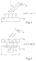
- Fig. 1 shows a radio base station RBS 20 0 with (here) four antenna elements having the same polarization connected thereto over antenna ports, on the antenna part, and feeder ports, which are the ports of the RBS (Radio Base Station).
- the antenna part may e.g. comprise a uniform linear array (ULA) with four antenna elements, with an element spacing dr in the base station. It here communicates with a single antenna in a user equipment UE 9 0 .
- the antenna elements are located so close to each other, typically half a wavelength, that the radio channel between the antenna in UE 9 0 and the ULA in RBS 20 0 in many cases are highly correlated. This means that they are almost identical for all base station antenna elements, except for a direction of arrival dependant phase shift corresponding to the difference in path length in communication with the UE.
- a ⁇ e j - N - 1 / 2 kd sin ⁇ ) e j - N - 3 / 2 kd sin ⁇ ) ... ... e j - N - 1 / 2 kd sin ⁇ ) T
- the total radio channel h which is estimated from the received signal vector, is composed by the array response vector and a complex channel amplification c which is assumed to be identical for all antenna elements, the transmitted signal is denoted x and interference including thermal noise is denoted n.
- the channel rank is 1 in this case with only one antenna at the UE, there is only one eigenvalue > 0.
- the eigenvector corresponding to that eigenvalue is a replica of the array response a( ⁇ ) except for a complex scaling factor.
- this vector is applied as a transmit weight vector, a beam pointing in the direction of the UE will result.
- Fig. 2 shows a state of the art arrangement with an antenna part 10' 0 with dual polarized antenna means, a processing unit 21 0 which performs an eigenvalue decomposition of channel estimates for finding an eigenvector to be applied for feeding the antenna elements.
- the magnitude variation in the weigth vector results in that, since the largest magnitude will limit the output power in order not to overload the power amplifier, the available power resources will not be utilized in an optimal way (unless somehow used by other simultaneous users) and resource usage will be limited
- an eigenvalue decomposition is performed over all elements in the antenna array to find eigenvalues and eigenvectors.
- the finding of eigenvalues and eigenvectors does not require any information about the architecture of the antenna array, which traditionally has been seen as an advantage.
- the amplitude varies over the elements in the weight vector (eigenvector) which results in a reduction of the available maximal output power to the concerned UE for common radio architectures.
- EP 1 315 311 and US 2007/171811 show base station arrangements with antenna elements having each an antenna port which are connected to a signal processing unit, further comprising signal pre-processing means collecting channel correlation information received over the antenna ports from user stations, and providing for detection of distinguishing characteristics of the antenna element channels.
- the processing unit is used to group antenna elements depending on the distinguishing features and to weight information to antenna elements for transmit power controlling purposes. However, the available output power is not used optimally in separate power amplifiers feeding antenna elements and the output power will be limited. Processing is furthermore done by the user stations.
- a base station arrangement as initially referred to wherein antenna elements of an antenna part are connected by means of antenna ports to the base station arrangement, which base station arrangement comprises the characterizing features of claim 1.
- state of the art decomposition based methods do not use or need information about antenna array architecture.
- information often actually is available since it might be needed for other purposes. If for example some signals are to be transmitted not only to a specific user, but over an entire cell, then such a cell covering transmission will depend on the antenna array architecture and it requires knowledge about the architecture.
- An example where such information is needed for other purposes is in TD-SCDMA (Time Division - Synchronous Code Division Multiple Access) where a cell covering transmission over four dual polarized columns is achieved by applying a phase taper, possibly also an amplitude taper, over the antenna elements.
- the architecture of the antenna path is thus known even if the information is not needed for eigenvalue decomposition. According to the present invention it is proposed to further exploit such information. However, also in cases where such information is not collected or directly available, since it is needed for other purposes, it is, according to the present invention, suggested to collect such information.
- a method as initially referred to is also provided which has the characterizing features of claim 10.
- the inventive concept is applicable to conventional systems as well as to so called active systems where the radio is built in in the antenna, e.g. then comprising a base station and antenna arrangement.
- Fig. 3 is a block diagram of a base station arrangement 100 of the present invention according to a first implementation. It is connected to an antenna part 10 with a plurality of first antenna elements 1 1 , 2 1 , 3 1 , 4 1 having a first polarization and a plurality of second antenna elements 1 2 , 2 2 , 3 2 , 4 2 of another polarization, which is different from said first polarization.
- the antenna part 10 thus here comprises four, dual polarized antenna means or antennas.
- Each antenna element has an antenna port 11 1 ,11 2 ,...,11 8 which ports here are consecutively numbered for the respective antenna means for reasons of simplicity.
- the base station arrangement 21 comprises a plurality of antenna ports, here called feeder ports 21 1 ,...,21 8 to which the respective antenna ports are connected by feeder cables. Each feeder port is connected to a respective power amplifying unit 41 1 ,...,41 8 .
- Different kinds of controllable amplifying means can be used, the invention not being limited to any specific kind.
- the base station arrangement 21 comprises a signal pre-processing functional unit 30 which in this embodiment is supposed to be a unit which is separate from the processing unit 20.
- the pre-processing functionality can also be performed by a pre-processing function included in the processing unit 20, c.f. for example Fig. 5 , or by the processing unit itself.
- the signal pre-processing unit (SPPU) 30 collects channel correlation information from uplink channels and, here, detecting means 22 are provided for detecting or establishing the element (or more precisely channel) correlation.
- the detecting means 22 may be provided in the signal pre-processing unit 30 or in the processing unit, as it is shown in Fig. 3 .
- the processing unit 20 further comprises grouping means 23 adapted to, based on such correlation information, arrange or assign antenna elements into different groups.
- the grouping means 23 may alternatively be provided in the signal pre-processing unit 30.
- the processing unit further comprises a means 24 or a functionality suitable for performing an eigenvalue decomposition.
- the eigenvalue decomposition is done for all antenna elements in order to enable control of the electrical phase and thus polarization. It should be clear that the eigenvalue decomposition can be done before the grouping in the grouping means or vice versa, i.e. after the grouping.
- the grouping means 23 are adapted to, based on correlation related information, find elements with a high channel correlation and to group them together.
- the elements of the vector are organized into groups, based on the channel element grouping.
- each group or sub-vector
- the elements within each group, or sub-vector, are magnitude normalized within respective group. Since in Fig. 3 the antenna means are dual polarized, i.e. the antenna elements are of two different polarizations, there will be two sub-vectors w 1 , w 2 to be applied to the antenna elements of either group, here elements from a weight vector w 1 is applied to antenna elements 1 2 , 2 2 , 3 2 and 4 2 whereas another weight vector w 2 is applied to antenna element 1 1 , 2 1 , 3 1 , 4 1 .
- the important feature is that the power settings are done independently per group and that it thus becomes possible to maximize the transmit power by setting the power to P max , limited by the resource, i.e. power amplified per branch, for the limiting branch per group rather than for the total of all branches.
- the distinguishing feature is the polarization, detected as different correlation properties. According to the invention it is sufficient to detect that the correlation properties differ, or that channels are uncorrelated, it is not necessary to know why, e.g. if it is due to different polarizations or something else. Within each polarization, a beam will then be directed in the best possible direction, and the received power at the user equipment UE (not shown in this figure, compare for example Fig. 2 ) is maximized.
- power can be controlled independently for each group. Fundamental is that uplink information, correlation related information, is taken advantage of and used for calculating eigenvectors and also for grouping purposes. It should also be clear that there may be other distinguishing characteristics, known or unknown, and/or that there may be assignment into more than two groups.
- grouping can be done a priori based on configuration information that may be provided in other manners and does not need to be based on actual estimates of the correlation matrix. For single polarized antenna parts with a high correlation there will be one group only, whereas for a dual polarized antenna parts (antennas) there will be two groups, one per polarization since e.g. vertical and horizontal polarization components fade independently.
- CI SPPU 30
- ⁇ x(CI) 22 indicates the establishment of distinguishing characteristics.
- Fig. 4 shows a base station arrangement 200 connected to or comprising an antenna part 10A, with dual polarized antenna means, comprising a number of first antenna elements 1A 1 , 2A 1 , 3A 1 , 4A 1 of a first polarization and second antenna elements 1A 2 , 2A 2 , 3A 2 , 4A 2 of another, different, second polarization.
- first antenna elements 1A 1 , 2A 1 , 3A 1 , 4A 1 of a first polarization and second antenna elements 1A 2 , 2A 2 , 3A 2 , 4A 2 of another, different, second polarization.
- the fading will be independent for vertical and horizontal polarization components.
- the base station processing unit comprises an eigenvalue decomposition means 24A arranged to, with magnitude normalization independently for each group, form a weight vector for each group (polarization).
- Weight vector w 1 is applied to second antenna elements 1A 2 , 2A 2 , 3A 2 , 4A 2 and weight vector w 2 is applied to first antenna elements 1A 1 ,...,4A 1 .
- the application of the respective transmit power is performed by means of amplifying means 41A 1 ,...,41A 8 .
- Fig. 5 shows another embodiment of a base station arrangement 300 connected to or comprising an antenna part 10B comprising three first antenna elements 1B 1 , 2B 1 , 3B 1 with a first polarization and three antenna elements 1B 2 , 2B 2 , 3B 2 with another, different polarization and which are connected to antenna ports 11B 1 , ...,11B 6 .
- the signal pre-processing functionality is included in the processing unit 20B of the base station arrangement 21B.
- detecting means 22B implemented as hardware and/or software, are provided for establishing distinguishing characteristic, which also in this case is different correlation properties (here caused by different polarizations).
- Grouping means 23B which may be combined with the detecting means or implemented as separate hardware and software means, are adapted to group antenna elements correspondingly into two groups.
- An eigenvalue decomposition is performed to find eigenvectors for the respective groups in eigenvalue decomposition means 24B.
- the eigenvalue decomposition has to be based on all antenna elements, using the correlation information provided by SPPU 30B, and it also can be done before the grouping step. Finally the respective weight vectors w 1 , w 2 are applied to the two antenna element groups.
- Fig. 6 shows an embodiment not falling within the scope of the claims with a single polarized antenna part 10C comprising, here, four antenna elements 1C, 2C, 3C, 4C arranged in two groups or on two separate antenna means, which may have different locations, directions etc.
- the antenna means have different spatial directions, the spatial directions hence producing the distinguishing characteristic, (different correlation properties) or they are spatially separated hence forming the distinguishing characteristic in both examples such that channel correlation between the two groups of elements becomes low.
- the elements may also have arbitrary polarizations (not shown).
- a signal pre-processing unit 30C comprising collecting means 31C collect correlation related information, and detecting means 32C are provided for detecting if correlation properties are different, if elements are uncorrelated.
- This information is used by grouping means 33C where the antenna elements are grouped into two different groups, in this case into different groups corresponding to antenna elements 1C and 2C and 3C and 4C respectively.
- processing unit 20C an eigenvalue decomposition is performed in eigenvalue decomposition algorithm holding means 24C resulting in different eigenvectors to be applied to the two groups.
- w 1 is applied to antenna elements 1C, 2C whereas w 2 is applied to antenna elements 3C, 4C.
- Fig. 7 shows a base station arrangement 500 connected to (or comprised in) an antenna part 10D.
- the base station arrangement comprises a processing unit 20D and a pre-processing unit 30D.
- the antenna part 10D comprises a plurality of first antenna elements 1D 1 , 2D 1 , 3D 1 , 4D 1 of a first polarization and a plurality of second antenna elements 1D 2 , 2D 2 , 3D 2 , 4D 2 of a second polarization.
- a signal pre-processing functional unit 30D is provided for collecting channel correlation information. Also in this case it is shown as forming a separate means or separate processor but it may as well be included in the processing unit 20D.
- the processing unit comprises means for performing an eigenvalue decomposition 34D which in this embodiment is done after grouping, which is done in the grouping means 33D using separately provided configuration related information.
- the configuration information is supposed to be fixed and stored and here the antenna elements 1D 1 , 2D 1 , 3D 1 , 4D 1 are associated with a first distinguishing characteristic C1, whereas the antenna elements 1D 2 , 2D 2 , 3D 2 , 4D 2 , are associated with distinguishing characteristic C2, different from C1. It can also be seen as a characteristic for which the values are different.
- This information may be provided as configuration information by an operator in any appropriate manner or it may be held in the storing means 32D for a longer or a shorter time period, the storing means may for example comprise a cache or some other storing facility.
- the grouping is done independently from the correlation information. The grouping may then also be done a priori and be held in the storing means 32D in Fig. 7 .
- the distinguishing characteristic is the polarization. As also discussed above the eigenvalue decomposition is done on all elements. Correlation information is used to provide the weight vectors.
- Fig. 8 shows a base station and antenna arrangement 600 according to still another implementation.
- the antenna part 10E comprises dual polarized antenna means, each with a first antenna element 1E 1 ,...,4E 1 with a first polarization and a second antenna element 1E 2 ,...,4E 2 of another polarization.
- the antenna part also comprises a plurality of antenna ports, 11E 1 ,...,11E 8 .
- the base station arrangement comprises a signal pre-processing unit adapted to collect correlation related information and detecting means 22E for establishing if there are any groups of elements having low correlation between the groups. Here it can be established that the correlation is low between certain antenna elements. Based thereupon the antenna elements are arranged into different groups in grouping means 23E.
- the grouping can be done before or after performing an eigenvalue decomposition.
- the signal pre-processing function unit in this embodiment also is connected to decision means 55E which may determine to switch over between connecting to means 50E for performing a conventional eigenvalue decomposition to find a single eigenvector to be used for transmission or to eigenvalue decomposition means 24E, according to the present invention, based on the grouping for individual power setting for different groups.
- decision means 55E may determine to switch over between connecting to means 50E for performing a conventional eigenvalue decomposition to find a single eigenvector to be used for transmission or to eigenvalue decomposition means 24E, according to the present invention, based on the grouping for individual power setting for different groups.
- it can be switched to eigenvalue decomposition means 24E wherein, for each group, a respective vector, being subsets of the original eigenvector, is used.
- a switch is done to the decomposition means 50E.
- the decision may be based on external information or additional information or any information as provided by correlation information etc. In one embodiment the decision is based on the numbers of streams or layers that are used for communication between UE and RBS. Individual or groupwise application of weight vectors is applicable for single layer transmission. Even if two layer transmission is supported, sometimes, still, one layer, or one stream, communication is only used and then groupwise transmission control, according to the inventive concept, can be used. If conventional eigenvalue decomposition is implemented, for all antenna elements, transmit power will be controlled by means of the same weight vector w 0 .
- the number of antennas on the uplink and downlink are the same enabling direct application of the suggested group or individual based transmit power control.
- Fig. 9 discloses the relation between the power received at the UE with the inventive method and the power received using the conventional method, P UE,2 /P UE,1 , is illustrated. It can be seen that a power which is considerably higher can be received at the UE through the use of the inventive concept.
- One effect of increasing the output power for an element with a low amplitude as given by the eigen value decomposition is that power in a polarization orthogonal to the UE antenna will occur. This power will not be received by the UE.
- Simulations have been performed also for fading channels for dual polarized radio base station antennas. Performance for fading channels are illustrated for a dual polarized antenna with +/- 45° polarization in Fig. 10A and for a dual polarized antenna part with antennas having horizontal and vertical polarizations respectively in Fig. 10B .
- Fig. 10A , 10B show the average power gain and 10,50 and 90 percentile gains for received power relation of the method according to the present invention versus the state of the art method as discussed above, for +/- 45° ( Fig. 10A ) and 0°/90° ( Fig 10B ) for both channel polarizations having the same average power gain.
- the gain depends on antenna orientation in the UE, the channel conditions as well as antenna configuration in the base station. In all cases there is a gain in the order of 1 dB for most UE antenna orientations.
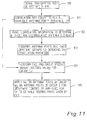
- a signal transmitted from a UE is received in a base station arrangement, 100.
- Channel correlation related information is collected for all available antenna ports, 101.
- a distinguishing characteristic e.g. low correlation between elements, is concluded using the channel correlation information.
- a low correlation may result from different polarizations etc.
- the signals from antenna ports are grouped into, here, two different groups depending on the correlation properties; a high correlation between elements indicate that they should be grouped into the same group etc., 103.
- an eigenvalue decomposition is performed using correlation information, and group specific weight vectors w 1 , w 2 are found, 104.
- the eigenvalue decompositions have to be performed for all elements.
- EVD eigenvalue decompositions
- Fig. 12 is a flow diagram schematically describing a procedure when configuration information, which for example is static, is provided separately.
- a signal transmitted from an UE is received in a base station arrangement, 200, and correlation related information is collected, 201.
- configuration information concerning antenna elements is provided to the radio base station 201, and antenna elements are grouped into groups depending on distinguishing characteristic, for example if the antenna elements have two different polarizations, 202A. The information needed for grouping may then be already available in the base station and fetched beforehand, or be fetched when an EVD has been performed on all antenna elements.
- Different group specific weight vectors w 1 , w 2 are obtained, using correlation information, for groups 1, 2 (if there are two different groups), 203.
- the weigth vector w 1 is then applied to antenna ports for antenna elements of group 1 and w 2 to the antenna ports of antenna elements of group 2 enabling control of the amplitude groupwise while keeping the phases as given by the EVD in step 203 above, 204.
- Fig. 13 is a flow diagram describing an implementation enabling selection between the use of a conventional eigenvalue decomposition method and an eigenvalue decomposition for groupwise power, amplitude, control according to the present invention. It is supposed that a signal trasmitted from an UE is received in a radio base station, 300. As described above correlation information is collected from each available antenna port, 301. Some relevant information is used to assist in the decision concerning use of conventional EVD decomposition or EVD for groupwise control. This information may comprise transmission related information, for example determination of the number of streams to be transmitted, bearing in mind that EVD for groupwise control according to the present invention is applicable for single layer transmission.
- information may comprise information about if a MIMO (Multiple Input Multiple Output) communication system is used, or even if MIMO is implemented, if for example only one stream is used, which makes the inventive concept directly applicable, 301A. Also other information may be relevant for making the decision.
- power maximization groupwise control
- a uniform, conventional EVD is performed and a single weight vector w 0 is found, 304B. The weight vector w 0 is then applied on all available antenna ports for transmission to the UE, 305B.
- the correlation information is used to see if there are any distinguishing characteristics, 303A, between antenna elements (i.e. the channels associated therewith), and the antenna elements are grouped depending on the outcome of the examination, whereby antenna elements having a high correlation are grouped into one and the same group. Then an EVD is performed on all antenna elements as discussed above, weight vectors w 1 , w 2 are found, 305A, and the amplitude is adjusted groupwise whereas the phases given by the EVD are kept by applying w 1 on group 1 antenna ports and w 2 on group 2 antenna ports to control antenna element transmit power, 306A.
- the invention can be varied in a number of ways without departing from the scope of the invention. Particularly it should be clear that instead of an eigenvalue decomposition of the channel correlation matrix, a single value decomposition of the channel itself could be performed. It should also be clear that the invention is not limited to e.g. four dual polarized antenna means, but there can be any number of single or dual polarized antenna means. Other kinds of polarizations are also possible, elliptical etc. In some embodiment already existing, hardware is used, whereas in other embodiments additional dedicated hardware is used to perform the respective functions.
- the inventive concept is applicable to conventional systems as well as to active antennas, wherein the radio functionality is built into the antenna.
Landscapes
- Engineering & Computer Science (AREA)
- Computer Networks & Wireless Communication (AREA)
- Signal Processing (AREA)
- Mobile Radio Communication Systems (AREA)
- Radio Transmission System (AREA)
- Variable-Direction Aerials And Aerial Arrays (AREA)
Claims (15)
- Agencement de station de base (100 ; 200 ; 300 ; 400 ; 500 ; 600) apte à, sur des canaux de communication radio, recevoir des signaux en provenance d'une station d'utilisateur, et transmettre des signaux à une station d'utilisateur, et apte à être connecté à, ou comportant, une partie d'antenne (10 ; 10A ; 10B ; 10C ; 10D ; 10E) avec une pluralité d'éléments d'antenne (11, 12, 21, 22, ..., 41, 42 ; 1A1, 1A2, 2A1, 2A2, ..., 4A1, 4A2 ; 1B1, ..., 3B2 ; 1C, 2C, 3C, 4C ; 1D1, ..., 4D2 ; 1E1, ..., 4E2) avec un port d'antenne (11, ..., 118, 11A1, ..., 11A8 ; 11B1, ..., 11B6 ; 11C1, ..., 11C4 ; 11D1, ..., 11D8 ; 11E1, ..., 11E8) pour chaque élément d'antenne, et comprenant une unité de traitement de signal (20 ; 20A ; 20B ; 20C ; 20D ; 20E) à laquelle les ports d'antenne sont connectés, et un nombre d'unités d'amplification de puissance (411, ..., 418 ; 41A1, ..., 41A8 ; 41B1, ..., 41B6 ; 41C1, ..., 41C4 ; 41D1, ..., 41D8 ; 41E1, ..., 41E8),
comprenant :une unité fonctionnelle de prétraitement de signal (30 ; 30A ; 30B ; 30C ; 30D ; 30E) qui est apte à collecter des informations de corrélation de canaux à partir de signaux reçus en provenance de la station d'utilisateur sur les ports d'antenne ;un moyen de détection (22 ; 32A ; 22B ; 32C) apte à détecter ou reconnaître s'il existe une ou plusieurs caractéristiques distinctives associées à des canaux associés aux éléments d'antenne, une caractéristique distinctive comprenant une ou plusieurs propriétés de corrélation distinctives et/ou propriétés distinctives connexes à la configuration fournies séparément,caractérisé en ce que l'unité de traitement (20A ; 20B ; 20C ; 20D ; 20E) ou l'unité fonctionnelle de prétraitement de signal (30A ; 30B ; 30C ; 30D ; 30E) est apte à affecter des éléments d'antenne à différents groupes sur la base de propriétés de corrélation distinctives, et/ou de propriétés de configuration distinctives ; etcaractérisé en ce quel'unité de traitement (20, 20A ; 20B ; 20C ; 20D ; 20E) est apte à utiliser les informations de corrélation de canaux en vue de générer des informations de pondération, et à appliquer lesdites informations de pondération à des éléments d'antenne en vue de commander la puissance d'émission d'éléments d'antenne en vue d'une transmission à la station d'utilisateur, de sorte que la puissance d'émission peut être définie indépendamment pour lesdits différents groupes ;caractérisé en ce qu'il est apte à être connecté à, ou comporte une partie d'antenne, dans laquelle des seconds éléments d'antenne (12, 22, 32, 42 ; 1A2, 2A2, 3A2, 4A2 ; 1B2, 2B2, 3B2, 4B2 ; 3C, 4C ; 1D2, 2D2, 3D2, 4D2 ; 1E2, 2E2, 3E2, 4E2) sont associés à au moins une caractéristique qui est différente d'une caractéristique correspondante d'un premier élément d'antenne (11, 21, 31, 41 ; 1A1, 2A1, 3A1, 4A1 ; 1B1 ; 2B1 ; 3B1 ; 1C, 2C ; 1D1, 1D2, 1D3, 1D4 ; 1E1, 1E2, 1E3, 1E4), ladite au moins une caractéristique distinctive correspondant à la polarisation, les premiers éléments d'antenne (11, 21, 31, 41 ; 1A1, 2A1, 3A1, 4A1 ; 1B1 ; 2B1 ; 3B1 ; 1D1, 1D2, 1D3, 1D4 ; 1E1, 1E2, 1E3, 1E4) présentant une première polarisation et les seconds éléments d'antenne (12, 22, 32, 42 ; 1A2, 2A2, 3A2, 4A2 ; 1B2, 2B2, 3B2, 4B2 ; 1D2, 2D2, 3D2, 4D2 ; 1E2, 2E2, 3E2,4E2) présentant une seconde polarisation, différente de ladite première polarisation, et en ce que lesdits premiers et seconds éléments d'antenne sont affectés à différents groupes en fonction de l'existence de cette caractéristique distinctive. - Agencement de station de base selon la revendication 1,
caractérisé en ce que
il est apte à être connecté à, ou comporte, une partie d'antenne dans laquelle les premiers et seconds éléments d'antenne présentent une polarisation linéaire, les premiers éléments d'antenne présentant une polarisation verticale linéaire et les seconds éléments d'antenne présentant une polarisation horizontale linéaire, ou inversement, ou en ce que les premiers et seconds éléments d'antenne présentent une polarisation circulaire, les premiers éléments d'antenne étant polarisés vers la gauche et les seconds éléments d'antenne étant polarisés vers la droite, ou inversement ; ou en ce que les premiers et seconds éléments d'antenne présentent des polarisations elliptiques non parallèles, ou en ce que les premiers et seconds éléments d'antenne présentent une polarisation linéaire qui est de + 45° ou de -45° pour un premier élément d'antenne et de -45° ou de +45° pour un second élément d'antenne, respectivement, et en ce que des informations sur les différents états de polarisation sont fournies séparément, et sont utilisées en vue d'affecter des éléments à différents groupes, ou en ce que le regroupement est basé sur des propriétés de corrélation. - Agencement de station de base selon la revendication 1 ou 2,
caractérisé en ce que
l'unité de prétraitement de signal (30, 30A ; 30B ; 30C ; 30D ; 30E) est apte à extraire des informations connexes à l'amplitude et à la phase de canal radio, pour chaque élément d'antenne, de signaux reçus sur chaque port d'antenne disponible, en ce qu'une caractéristique distinctive supplémentaire différente comprend des propriétés de corrélation qui sont différentes sous l'effet de différentes amplitudes spatiales et/ou de différentes distributions de phase, et en ce que l'unité de traitement ou l'unité de prétraitement de signal est apte à mettre en oeuvre le regroupement d'éléments d'antenne sur la base desdites différentes propriétés de corrélation sans informations sur ce qui occasionne les différentes propriétés de corrélation. - Agencement de station de base selon l'une quelconque des revendications précédentes,
caractérisé en ce que
l'unité de traitement (20, 20A ; 20B ; 20C ; 20D ; 20E) est apte à utiliser les informations de corrélation pour former une matrice de corrélation de canaux comprenant un nombre d'éléments de matrice, et mettre en oeuvre une décomposition en valeurs propres pour tous les éléments donnant les informations de pondération comprenant des vecteurs de pondération avec des éléments appartenant à différents groupes et à ajuster l'amplitude des éléments d'antenne des différents groupes, séparément, tout en maintenant la phase telle que donnée par la décomposition en valeurs propres. - Agencement de station de base selon l'une quelconque des revendications précédentes,
caractérisé en ce que
l'unité fonctionnelle de prétraitement de signal (30, 30A ; 30B ; 30C ; 30D ; 30E) est apte à être connectée aux ports d'antenne, et en ce qu'elle est apte à extraire ou à collecter les informations de corrélation de canaux radio des ou à partir des signaux reçus. - Agencement d'antenne de station de base selon l'une quelconque des revendications 1 à 2,
caractérisé en ce que
il comporte ou est connecté à un moyen de gestion de configuration (32D), en ce que le moyen de gestion de configuration (32D) est apte à recevoir des informations connexes à une configuration statique en provenance d'un moyen externe, d'un opérateur ou d'un fabricant, et en ce que l'unité de configuration ou le moyen de détection de l'unité de prétraitement ou de l'unité de traitement est apte à utiliser les informations de configuration statique pour le regroupement des éléments d'antenne. - Agencement de station de base selon l'une quelconque des revendications 1 à 6,
caractérisé en ce que
l'unité de prétraitement de signal est agencée séparément, ou est intégrée dans l'unité de traitement. - Agencement de station de base selon l'une quelconque des revendications précédentes,
caractérisé en ce que
l'agencement d'antenne de station de base comprend une seconde unité de traitement (50E), outre ladite unité de traitement (24E), ou une unité de traitement étendue, et en ce qu'il est exploitable dans un premier mode opérationnel prenant en charge une commande de puissance/amplitude en groupes d'éléments d'antenne, et dans un second mode opérationnel classique, dans lequel l'unité de traitement (50E) est apte à générer un unique vecteur de pondération commun pour tous les éléments d'antenne, et en ce qu'il comprend en outre une unité de reconfiguration comprenant un moyen de gestion de décision (55E) apte à maintenir des critères de décision prédéterminés, et à, sur la base du respect des critères, sélectionner celui du premier mode opérationnel ou du second mode opérationnel qui doit être utilisé. - Agencement d'antenne de station de base selon la revendication 8,
caractérisé en ce que
les critères de décision peuvent être reconfigurés. - Procédé, mis en oeuvre dans un agencement comprenant un agencement de station de base radio avec une unité de traitement, de commande de transmission en liaison descendante à une station d'utilisateur, comprenant l'étape ci-dessous consistant à :- recevoir des signaux dans l'agencement de station de base à partir de la station d'utilisateur sur une partie d'antenne,
comprenant les étapes ci-dessous consistant à :- collecter ou maintenir, à partir des signaux reçus en provenance de la station d'utilisateur au niveau d'une pluralité de ports d'antenne de la partie d'antenne, des informations connexes à une corrélation concernant les canaux radio associés à des éléments d'antenne à partir desquels les signaux sont reçus sur des ports d'antenne disponibles ;- utiliser des informations connexes à une corrélation ou des informations connexes à une configuration, en vue de déterminer s'il existe des éléments d'antenne pour lesquels il existe une ou plusieurs caractéristiques distinctives associées aux canaux, comprenant différentes propriétés de corrélation ou différentes propriétés de configuration, et le cas échéant : affecter de tels éléments d'antenne à différents groupes ;- générer, dans l'unité de traitement, en utilisant les informations de corrélation, des informations de pondération connexes à des groupes, pour une alimentation électrique individuelle ou en groupes d'éléments d'antenne associés à des canaux non corrélés et/ou à des canaux présentant différentes propriétés de configuration ;- appliquer les informations de pondération connexes à des groupes aux ports d'antenne des éléments d'antenne des groupes respectifs par l'intermédiaire d'un moyen d'amplification, tout en définissant une puissance d'émission, de manière indépendante, pour les différents groupes, caractérisé en ce qu'il comprend en outre l'étape ci-dessous consistant à :- regrouper, dans l'unité de prétraitement de signal ou dans l'unité de traitement, les éléments d'antenne, en fonction d'une première caractéristique distinctive connue ou inconnue comprenant différentes propriétés de corrélation ou différentes propriétés de configuration, dans lequel la première caractéristique produisant des canaux de différentes propriétés de corrélation, ou des canaux non corrélés, correspond à la polarisation dans un système de coordonnées mondial qui est commun pour tous les éléments d'antenne. - Procédé selon la revendication 10,
caractérisé en ce que
une seconde caractéristique distinctive supplémentaire, qui est détectée sous la forme de différentes propriétés de corrélation, est produite par différentes amplitudes spatiales ou distributions de phase. - Procédé selon l'une quelconque des revendications 10 à 11,
caractérisé en ce que
l'étape de collecte consiste à :- extraire dynamiquement les informations de corrélation des signaux reçus dans l'unité de prétraitement de signal ou dans l'unité de traitement. - Procédé selon l'une quelconque des revendications 10 à 12,
caractérisé en ce que
l'étape de collecte consiste à :- recevoir en provenance d'un moyen externe, ou maintenir, dans un moyen de gestion de configuration, des informations de configuration statique concernant des éléments d'antenne ;- regrouper les éléments d'antenne présentant différentes propriétés de configuration dans différents groupes. - Procédé selon l'une quelconque des revendications 10 à 13,
caractérisé en ce que
il comprend les étapes ci-dessous consistant à :- mettre en oeuvre une décomposition en valeurs propres d'une matrice de corrélation de canaux formée par les informations de corrélation pour chaque groupe ;- appliquer différentes informations de pondération comportant des vecteurs de pondération spécifiques aux groupes, en appliquant les vecteurs de pondération spécifiques aux groupes aux différents groupes, de sorte que la puissance d'émission appliquée à des éléments d'antenne d'un groupe est indépendante de la puissance d'émission appliquée à un autre groupe, tout en maintenant la phase telle que donnée par la décomposition en valeurs propres. - Procédé selon l'une quelconque des revendications 10 à 14,
caractérisé en ce que
il comprend les étapes ci-dessous consistant à :- estimer des états d'antenne et/ou de canal en vue d'une communication avec la station d'utilisateur ;- utiliser un ou plusieurs critères prédéterminés en vue de déterminer si une exploitation dans un premier mode appliquant une alimentation électrique d'éléments d'antenne individuels ou en groupes doit être appliquée ; sinon,- commuter sur un second mode dans lequel une alimentation électrique d'éléments d'antenne uniformes est mise en oeuvre.
Applications Claiming Priority (1)
| Application Number | Priority Date | Filing Date | Title |
|---|---|---|---|
| PCT/EP2009/057046 WO2010142319A1 (fr) | 2009-06-08 | 2009-06-08 | Dispositifs pour stations de base |
Publications (2)
| Publication Number | Publication Date |
|---|---|
| EP2441180A1 EP2441180A1 (fr) | 2012-04-18 |
| EP2441180B1 true EP2441180B1 (fr) | 2016-02-17 |
Family
ID=41510545
Family Applications (1)
| Application Number | Title | Priority Date | Filing Date |
|---|---|---|---|
| EP09779675.9A Not-in-force EP2441180B1 (fr) | 2009-06-08 | 2009-06-08 | Dispositifs pour stations de base |
Country Status (4)
| Country | Link |
|---|---|
| US (1) | US8934942B2 (fr) |
| EP (1) | EP2441180B1 (fr) |
| CN (1) | CN102577157B (fr) |
| WO (1) | WO2010142319A1 (fr) |
Families Citing this family (9)
| Publication number | Priority date | Publication date | Assignee | Title |
|---|---|---|---|---|
| US8526553B2 (en) * | 2009-06-08 | 2013-09-03 | Telefonaktiebolaget L M Ericsson (Publ) | Wireless communication node connections |
| KR101809918B1 (ko) * | 2011-08-04 | 2017-12-20 | 삼성전자주식회사 | 무선통신 시스템에서 하향링크 하이브리드 자동 재전송 요청 정보 전송 방법 및 장치 |
| CN105379142B (zh) | 2013-07-14 | 2019-06-18 | Lg 电子株式会社 | 在支持大规模天线的无线接入系统中使用天线相关性收发数据符号的方法 |
| WO2016000096A1 (fr) * | 2014-06-09 | 2016-01-07 | 华为技术有限公司 | Procédé et dispositif de mappage de ports d'antenne |
| CN105262520B (zh) * | 2014-07-18 | 2018-07-27 | 上海诺基亚贝尔股份有限公司 | 一种调整有源天线阵列及参考信号映射的方法和装置 |
| WO2016045724A1 (fr) * | 2014-09-24 | 2016-03-31 | Telefonaktiebolaget L M Ericsson (Publ) | Agencement d'antenne pour une atténuation de distorsion non linéaire |
| EP3577792A1 (fr) * | 2017-02-27 | 2019-12-11 | Huawei Technologies Co., Ltd. | Agencement d'antennes mimo |
| JP6774982B2 (ja) * | 2018-04-27 | 2020-10-28 | アンリツ株式会社 | キャリブレーションシステム及びキャリブレーション方法 |
| US11582621B2 (en) * | 2019-10-30 | 2023-02-14 | Zebra Technologies Corporation | Sensor-assisted technique for RF power normalization in locationing applications |
Family Cites Families (3)
| Publication number | Priority date | Publication date | Assignee | Title |
|---|---|---|---|---|
| JP4176463B2 (ja) * | 2000-08-10 | 2008-11-05 | 富士通株式会社 | 送信ダイバーシチ通信装置 |
| US7058367B1 (en) * | 2003-01-31 | 2006-06-06 | At&T Corp. | Rate-adaptive methods for communicating over multiple input/multiple output wireless systems |
| KR100768510B1 (ko) | 2005-10-24 | 2007-10-18 | 한국전자통신연구원 | 다중안테나를 사용하는 직교 주파수 분할 다중 접속시스템의 전송 장치 및 그 방법 |
-
2009
- 2009-06-08 EP EP09779675.9A patent/EP2441180B1/fr not_active Not-in-force
- 2009-06-08 US US13/376,437 patent/US8934942B2/en active Active
- 2009-06-08 CN CN200980159852.2A patent/CN102577157B/zh not_active Expired - Fee Related
- 2009-06-08 WO PCT/EP2009/057046 patent/WO2010142319A1/fr not_active Ceased
Also Published As
| Publication number | Publication date |
|---|---|
| US20120088537A1 (en) | 2012-04-12 |
| US8934942B2 (en) | 2015-01-13 |
| CN102577157A (zh) | 2012-07-11 |
| EP2441180A1 (fr) | 2012-04-18 |
| WO2010142319A1 (fr) | 2010-12-16 |
| CN102577157B (zh) | 2016-06-15 |
Similar Documents
| Publication | Publication Date | Title |
|---|---|---|
| EP2441180B1 (fr) | Dispositifs pour stations de base | |
| KR100749451B1 (ko) | Ofdm 기지국 시스템에서의 스마트 안테나 빔 형성 방법및 장치 | |
| US10794984B2 (en) | System, method and computer-readable medium for estimating direction of arrival of a signal incident on at least one antenna array | |
| EP2559168B1 (fr) | Détection omnidirectionnelle de spectres radio | |
| KR100464014B1 (ko) | 다중 입출력 이동 통신 시스템에서의 폐루프 신호 처리 방법 | |
| JP5264990B2 (ja) | データ伝送の方法及びシステム | |
| Nguyen et al. | Unequally sub-connected architecture for hybrid beamforming in massive MIMO systems | |
| EP2246937B1 (fr) | Procédé et dispositif de mise en forme de faisceau | |
| EP3639389B1 (fr) | Procédés et dispositifs de traitement de signaux de liaison montante | |
| US20200382346A1 (en) | Efficient sparse channel estimation based on compressed sensing | |
| EP2159931A1 (fr) | Système d'antenne communautaire en mode de boucle fermée et son procédé | |
| US10320461B2 (en) | System, method and computer-readable medium for estimating direction of arrival of a signal incident on at least one antenna array | |
| CN101536355A (zh) | 具有全向和扇形定向天线模式的自适应多天线系统 | |
| KR102041012B1 (ko) | 시분할 이중통신 다중 사용자 다중 안테나 환경에서 다중 안테나를 이용한 파일럿 오염 공격을 검출하는 방법 및 시스템 | |
| Yazdani et al. | Beam selection and discrete power allocation in opportunistic cognitive radio systems with limited feedback using ESPAR antennas | |
| KR20160046941A (ko) | 수신기 및 그것의 빔 공간 샘플링 방법 | |
| Tsakalaki et al. | Spectrum sensing using single-radio switched-beam antenna systems | |
| Elhag et al. | Angle of arrival estimation in smart antenna using MUSIC method for wideband wireless communication | |
| US20170346517A1 (en) | Adjusting an antenna configuration of a terminal device in a cellular communication system | |
| CN102457324B (zh) | 一种频分双工系统下行多用户多径波束赋形方法及装置 | |
| JP2008504773A (ja) | Mimoシステムにおけるビームステアリング | |
| US20150156651A1 (en) | Detection of user terminal distribution in a wireless communication system | |
| JP2007159130A (ja) | 分散型アンテナ移動通信システムにおける上り受信方法及び装置 | |
| KR101447027B1 (ko) | 다중 안테나 시스템의 빔포밍 장치 및 방법 | |
| Montagner et al. | Taming the complexity of mm-wave massive MIMO systems: Efficient channel estimation and beamforming |
Legal Events
| Date | Code | Title | Description |
|---|---|---|---|
| PUAI | Public reference made under article 153(3) epc to a published international application that has entered the european phase |
Free format text: ORIGINAL CODE: 0009012 |
|
| 17P | Request for examination filed |
Effective date: 20111122 |
|
| AK | Designated contracting states |
Kind code of ref document: A1 Designated state(s): AT BE BG CH CY CZ DE DK EE ES FI FR GB GR HR HU IE IS IT LI LT LU LV MC MK MT NL NO PL PT RO SE SI SK TR |
|
| DAX | Request for extension of the european patent (deleted) | ||
| 17Q | First examination report despatched |
Effective date: 20120911 |
|
| RAP1 | Party data changed (applicant data changed or rights of an application transferred) |
Owner name: TELEFONAKTIEBOLAGET LM ERICSSON (PUBL) |
|
| RAP1 | Party data changed (applicant data changed or rights of an application transferred) |
Owner name: TELEFONAKTIEBOLAGET L M ERICSSON (PUBL) |
|
| GRAP | Despatch of communication of intention to grant a patent |
Free format text: ORIGINAL CODE: EPIDOSNIGR1 |
|
| INTG | Intention to grant announced |
Effective date: 20151014 |
|
| GRAS | Grant fee paid |
Free format text: ORIGINAL CODE: EPIDOSNIGR3 |
|
| GRAA | (expected) grant |
Free format text: ORIGINAL CODE: 0009210 |
|
| AK | Designated contracting states |
Kind code of ref document: B1 Designated state(s): AT BE BG CH CY CZ DE DK EE ES FI FR GB GR HR HU IE IS IT LI LT LU LV MC MK MT NL NO PL PT RO SE SI SK TR |
|
| REG | Reference to a national code |
Ref country code: GB Ref legal event code: FG4D |
|
| REG | Reference to a national code |
Ref country code: CH Ref legal event code: EP |
|
| REG | Reference to a national code |
Ref country code: IE Ref legal event code: FG4D |
|
| REG | Reference to a national code |
Ref country code: AT Ref legal event code: REF Ref document number: 776055 Country of ref document: AT Kind code of ref document: T Effective date: 20160315 |
|
| REG | Reference to a national code |
Ref country code: DE Ref legal event code: R096 Ref document number: 602009036366 Country of ref document: DE |
|
| REG | Reference to a national code |
Ref country code: NL Ref legal event code: MP Effective date: 20160217 |
|
| REG | Reference to a national code |
Ref country code: LT Ref legal event code: MG4D |
|
| REG | Reference to a national code |
Ref country code: FR Ref legal event code: PLFP Year of fee payment: 8 |
|
| REG | Reference to a national code |
Ref country code: AT Ref legal event code: MK05 Ref document number: 776055 Country of ref document: AT Kind code of ref document: T Effective date: 20160217 |
|
| PG25 | Lapsed in a contracting state [announced via postgrant information from national office to epo] |
Ref country code: GR Free format text: LAPSE BECAUSE OF FAILURE TO SUBMIT A TRANSLATION OF THE DESCRIPTION OR TO PAY THE FEE WITHIN THE PRESCRIBED TIME-LIMIT Effective date: 20160518 Ref country code: ES Free format text: LAPSE BECAUSE OF FAILURE TO SUBMIT A TRANSLATION OF THE DESCRIPTION OR TO PAY THE FEE WITHIN THE PRESCRIBED TIME-LIMIT Effective date: 20160217 Ref country code: IT Free format text: LAPSE BECAUSE OF FAILURE TO SUBMIT A TRANSLATION OF THE DESCRIPTION OR TO PAY THE FEE WITHIN THE PRESCRIBED TIME-LIMIT Effective date: 20160217 Ref country code: NO Free format text: LAPSE BECAUSE OF FAILURE TO SUBMIT A TRANSLATION OF THE DESCRIPTION OR TO PAY THE FEE WITHIN THE PRESCRIBED TIME-LIMIT Effective date: 20160517 Ref country code: FI Free format text: LAPSE BECAUSE OF FAILURE TO SUBMIT A TRANSLATION OF THE DESCRIPTION OR TO PAY THE FEE WITHIN THE PRESCRIBED TIME-LIMIT Effective date: 20160217 |
|
| PG25 | Lapsed in a contracting state [announced via postgrant information from national office to epo] |
Ref country code: SE Free format text: LAPSE BECAUSE OF FAILURE TO SUBMIT A TRANSLATION OF THE DESCRIPTION OR TO PAY THE FEE WITHIN THE PRESCRIBED TIME-LIMIT Effective date: 20160217 Ref country code: NL Free format text: LAPSE BECAUSE OF FAILURE TO SUBMIT A TRANSLATION OF THE DESCRIPTION OR TO PAY THE FEE WITHIN THE PRESCRIBED TIME-LIMIT Effective date: 20160217 Ref country code: LV Free format text: LAPSE BECAUSE OF FAILURE TO SUBMIT A TRANSLATION OF THE DESCRIPTION OR TO PAY THE FEE WITHIN THE PRESCRIBED TIME-LIMIT Effective date: 20160217 Ref country code: LT Free format text: LAPSE BECAUSE OF FAILURE TO SUBMIT A TRANSLATION OF THE DESCRIPTION OR TO PAY THE FEE WITHIN THE PRESCRIBED TIME-LIMIT Effective date: 20160217 Ref country code: AT Free format text: LAPSE BECAUSE OF FAILURE TO SUBMIT A TRANSLATION OF THE DESCRIPTION OR TO PAY THE FEE WITHIN THE PRESCRIBED TIME-LIMIT Effective date: 20160217 Ref country code: PT Free format text: LAPSE BECAUSE OF FAILURE TO SUBMIT A TRANSLATION OF THE DESCRIPTION OR TO PAY THE FEE WITHIN THE PRESCRIBED TIME-LIMIT Effective date: 20160617 Ref country code: PL Free format text: LAPSE BECAUSE OF FAILURE TO SUBMIT A TRANSLATION OF THE DESCRIPTION OR TO PAY THE FEE WITHIN THE PRESCRIBED TIME-LIMIT Effective date: 20160217 |
|
| PGFP | Annual fee paid to national office [announced via postgrant information from national office to epo] |
Ref country code: FR Payment date: 20160628 Year of fee payment: 8 |
|
| PG25 | Lapsed in a contracting state [announced via postgrant information from national office to epo] |
Ref country code: DK Free format text: LAPSE BECAUSE OF FAILURE TO SUBMIT A TRANSLATION OF THE DESCRIPTION OR TO PAY THE FEE WITHIN THE PRESCRIBED TIME-LIMIT Effective date: 20160217 Ref country code: EE Free format text: LAPSE BECAUSE OF FAILURE TO SUBMIT A TRANSLATION OF THE DESCRIPTION OR TO PAY THE FEE WITHIN THE PRESCRIBED TIME-LIMIT Effective date: 20160217 |
|
| PGFP | Annual fee paid to national office [announced via postgrant information from national office to epo] |
Ref country code: DE Payment date: 20160628 Year of fee payment: 8 |
|
| REG | Reference to a national code |
Ref country code: DE Ref legal event code: R097 Ref document number: 602009036366 Country of ref document: DE |
|
| PG25 | Lapsed in a contracting state [announced via postgrant information from national office to epo] |
Ref country code: RO Free format text: LAPSE BECAUSE OF FAILURE TO SUBMIT A TRANSLATION OF THE DESCRIPTION OR TO PAY THE FEE WITHIN THE PRESCRIBED TIME-LIMIT Effective date: 20160217 Ref country code: CZ Free format text: LAPSE BECAUSE OF FAILURE TO SUBMIT A TRANSLATION OF THE DESCRIPTION OR TO PAY THE FEE WITHIN THE PRESCRIBED TIME-LIMIT Effective date: 20160217 Ref country code: SK Free format text: LAPSE BECAUSE OF FAILURE TO SUBMIT A TRANSLATION OF THE DESCRIPTION OR TO PAY THE FEE WITHIN THE PRESCRIBED TIME-LIMIT Effective date: 20160217 |
|
| PLBE | No opposition filed within time limit |
Free format text: ORIGINAL CODE: 0009261 |
|
| STAA | Information on the status of an ep patent application or granted ep patent |
Free format text: STATUS: NO OPPOSITION FILED WITHIN TIME LIMIT |
|
| PG25 | Lapsed in a contracting state [announced via postgrant information from national office to epo] |
Ref country code: BE Free format text: LAPSE BECAUSE OF FAILURE TO SUBMIT A TRANSLATION OF THE DESCRIPTION OR TO PAY THE FEE WITHIN THE PRESCRIBED TIME-LIMIT Effective date: 20160217 |
|
| 26N | No opposition filed |
Effective date: 20161118 |
|
| PG25 | Lapsed in a contracting state [announced via postgrant information from national office to epo] |
Ref country code: MC Free format text: LAPSE BECAUSE OF FAILURE TO SUBMIT A TRANSLATION OF THE DESCRIPTION OR TO PAY THE FEE WITHIN THE PRESCRIBED TIME-LIMIT Effective date: 20160217 |
|
| REG | Reference to a national code |
Ref country code: CH Ref legal event code: PL |
|
| PG25 | Lapsed in a contracting state [announced via postgrant information from national office to epo] |
Ref country code: BG Free format text: LAPSE BECAUSE OF FAILURE TO SUBMIT A TRANSLATION OF THE DESCRIPTION OR TO PAY THE FEE WITHIN THE PRESCRIBED TIME-LIMIT Effective date: 20160517 Ref country code: SI Free format text: LAPSE BECAUSE OF FAILURE TO SUBMIT A TRANSLATION OF THE DESCRIPTION OR TO PAY THE FEE WITHIN THE PRESCRIBED TIME-LIMIT Effective date: 20160217 |
|
| REG | Reference to a national code |
Ref country code: IE Ref legal event code: MM4A |
|
| PG25 | Lapsed in a contracting state [announced via postgrant information from national office to epo] |
Ref country code: CH Free format text: LAPSE BECAUSE OF NON-PAYMENT OF DUE FEES Effective date: 20160630 Ref country code: LI Free format text: LAPSE BECAUSE OF NON-PAYMENT OF DUE FEES Effective date: 20160630 |
|
| PG25 | Lapsed in a contracting state [announced via postgrant information from national office to epo] |
Ref country code: IE Free format text: LAPSE BECAUSE OF NON-PAYMENT OF DUE FEES Effective date: 20160608 |
|
| REG | Reference to a national code |
Ref country code: DE Ref legal event code: R119 Ref document number: 602009036366 Country of ref document: DE |
|
| REG | Reference to a national code |
Ref country code: FR Ref legal event code: ST Effective date: 20180228 |
|
| PG25 | Lapsed in a contracting state [announced via postgrant information from national office to epo] |
Ref country code: DE Free format text: LAPSE BECAUSE OF NON-PAYMENT OF DUE FEES Effective date: 20180103 |
|
| PG25 | Lapsed in a contracting state [announced via postgrant information from national office to epo] |
Ref country code: HU Free format text: LAPSE BECAUSE OF FAILURE TO SUBMIT A TRANSLATION OF THE DESCRIPTION OR TO PAY THE FEE WITHIN THE PRESCRIBED TIME-LIMIT; INVALID AB INITIO Effective date: 20090608 Ref country code: FR Free format text: LAPSE BECAUSE OF NON-PAYMENT OF DUE FEES Effective date: 20170630 Ref country code: CY Free format text: LAPSE BECAUSE OF FAILURE TO SUBMIT A TRANSLATION OF THE DESCRIPTION OR TO PAY THE FEE WITHIN THE PRESCRIBED TIME-LIMIT Effective date: 20160217 |
|
| PG25 | Lapsed in a contracting state [announced via postgrant information from national office to epo] |
Ref country code: MT Free format text: LAPSE BECAUSE OF NON-PAYMENT OF DUE FEES Effective date: 20160630 Ref country code: MK Free format text: LAPSE BECAUSE OF FAILURE TO SUBMIT A TRANSLATION OF THE DESCRIPTION OR TO PAY THE FEE WITHIN THE PRESCRIBED TIME-LIMIT Effective date: 20160217 Ref country code: TR Free format text: LAPSE BECAUSE OF FAILURE TO SUBMIT A TRANSLATION OF THE DESCRIPTION OR TO PAY THE FEE WITHIN THE PRESCRIBED TIME-LIMIT Effective date: 20160217 Ref country code: LU Free format text: LAPSE BECAUSE OF NON-PAYMENT OF DUE FEES Effective date: 20160608 Ref country code: IS Free format text: LAPSE BECAUSE OF FAILURE TO SUBMIT A TRANSLATION OF THE DESCRIPTION OR TO PAY THE FEE WITHIN THE PRESCRIBED TIME-LIMIT Effective date: 20160217 Ref country code: HR Free format text: LAPSE BECAUSE OF FAILURE TO SUBMIT A TRANSLATION OF THE DESCRIPTION OR TO PAY THE FEE WITHIN THE PRESCRIBED TIME-LIMIT Effective date: 20160217 |
|
| PGFP | Annual fee paid to national office [announced via postgrant information from national office to epo] |
Ref country code: GB Payment date: 20230627 Year of fee payment: 15 |
|
| GBPC | Gb: european patent ceased through non-payment of renewal fee |
Effective date: 20240608 |
|
| PG25 | Lapsed in a contracting state [announced via postgrant information from national office to epo] |
Ref country code: GB Free format text: LAPSE BECAUSE OF NON-PAYMENT OF DUE FEES Effective date: 20240608 |