EP2441602A1 - Wheel suspension with a spring-damper strut - Google Patents
Wheel suspension with a spring-damper strut Download PDFInfo
- Publication number
- EP2441602A1 EP2441602A1 EP10186998A EP10186998A EP2441602A1 EP 2441602 A1 EP2441602 A1 EP 2441602A1 EP 10186998 A EP10186998 A EP 10186998A EP 10186998 A EP10186998 A EP 10186998A EP 2441602 A1 EP2441602 A1 EP 2441602A1
- Authority
- EP
- European Patent Office
- Prior art keywords
- spring
- damper strut
- suspension
- damper
- steering
- Prior art date
- Legal status (The legal status is an assumption and is not a legal conclusion. Google has not performed a legal analysis and makes no representation as to the accuracy of the status listed.)
- Withdrawn
Links
- 239000000725 suspension Substances 0.000 title claims abstract description 38
- 230000015572 biosynthetic process Effects 0.000 abstract 1
- 239000006096 absorbing agent Substances 0.000 description 5
- 230000035939 shock Effects 0.000 description 2
- 230000002411 adverse Effects 0.000 description 1
- 230000006835 compression Effects 0.000 description 1
- 238000007906 compression Methods 0.000 description 1
- 238000010276 construction Methods 0.000 description 1
- 230000002349 favourable effect Effects 0.000 description 1
- 230000000087 stabilizing effect Effects 0.000 description 1
Images

Classifications
-
- B—PERFORMING OPERATIONS; TRANSPORTING
- B60—VEHICLES IN GENERAL
- B60G—VEHICLE SUSPENSION ARRANGEMENTS
- B60G15/00—Resilient suspensions characterised by arrangement, location or type of combined spring and vibration damper, e.g. telescopic type
- B60G15/02—Resilient suspensions characterised by arrangement, location or type of combined spring and vibration damper, e.g. telescopic type having mechanical spring
- B60G15/06—Resilient suspensions characterised by arrangement, location or type of combined spring and vibration damper, e.g. telescopic type having mechanical spring and fluid damper
- B60G15/062—Resilient suspensions characterised by arrangement, location or type of combined spring and vibration damper, e.g. telescopic type having mechanical spring and fluid damper the spring being arranged around the damper
-
- B—PERFORMING OPERATIONS; TRANSPORTING
- B60—VEHICLES IN GENERAL
- B60G—VEHICLE SUSPENSION ARRANGEMENTS
- B60G13/00—Resilient suspensions characterised by arrangement, location or type of vibration dampers
- B60G13/001—Arrangements for attachment of dampers
- B60G13/005—Arrangements for attachment of dampers characterised by the mounting on the axle or suspension arm of the damper unit
- B60G13/006—Arrangements for attachment of dampers characterised by the mounting on the axle or suspension arm of the damper unit on the stub axle
-
- B—PERFORMING OPERATIONS; TRANSPORTING
- B60—VEHICLES IN GENERAL
- B60G—VEHICLE SUSPENSION ARRANGEMENTS
- B60G15/00—Resilient suspensions characterised by arrangement, location or type of combined spring and vibration damper, e.g. telescopic type
- B60G15/02—Resilient suspensions characterised by arrangement, location or type of combined spring and vibration damper, e.g. telescopic type having mechanical spring
- B60G15/06—Resilient suspensions characterised by arrangement, location or type of combined spring and vibration damper, e.g. telescopic type having mechanical spring and fluid damper
- B60G15/07—Resilient suspensions characterised by arrangement, location or type of combined spring and vibration damper, e.g. telescopic type having mechanical spring and fluid damper the damper being connected to the stub axle and the spring being arranged around the damper
-
- B—PERFORMING OPERATIONS; TRANSPORTING
- B60—VEHICLES IN GENERAL
- B60G—VEHICLE SUSPENSION ARRANGEMENTS
- B60G3/00—Resilient suspensions for a single wheel
- B60G3/02—Resilient suspensions for a single wheel with a single pivoted arm
- B60G3/04—Resilient suspensions for a single wheel with a single pivoted arm the arm being essentially transverse to the longitudinal axis of the vehicle
- B60G3/06—Resilient suspensions for a single wheel with a single pivoted arm the arm being essentially transverse to the longitudinal axis of the vehicle the arm being rigid
-
- B—PERFORMING OPERATIONS; TRANSPORTING
- B60—VEHICLES IN GENERAL
- B60G—VEHICLE SUSPENSION ARRANGEMENTS
- B60G2200/00—Indexing codes relating to suspension types
- B60G2200/10—Independent suspensions
- B60G2200/14—Independent suspensions with lateral arms
- B60G2200/142—Independent suspensions with lateral arms with a single lateral arm, e.g. MacPherson type
-
- B—PERFORMING OPERATIONS; TRANSPORTING
- B60—VEHICLES IN GENERAL
- B60G—VEHICLE SUSPENSION ARRANGEMENTS
- B60G2200/00—Indexing codes relating to suspension types
- B60G2200/40—Indexing codes relating to the wheels in the suspensions
- B60G2200/422—Driving wheels or live axles
-
- B—PERFORMING OPERATIONS; TRANSPORTING
- B60—VEHICLES IN GENERAL
- B60G—VEHICLE SUSPENSION ARRANGEMENTS
- B60G2204/00—Indexing codes related to suspensions per se or to auxiliary parts
- B60G2204/10—Mounting of suspension elements
- B60G2204/12—Mounting of springs or dampers
- B60G2204/129—Damper mount on wheel suspension or knuckle
-
- B—PERFORMING OPERATIONS; TRANSPORTING
- B60—VEHICLES IN GENERAL
- B60G—VEHICLE SUSPENSION ARRANGEMENTS
- B60G2206/00—Indexing codes related to the manufacturing of suspensions: constructional features, the materials used, procedures or tools
- B60G2206/01—Constructional features of suspension elements, e.g. arms, dampers, springs
- B60G2206/50—Constructional features of wheel supports or knuckles, e.g. steering knuckles, spindle attachments
Definitions
- the invention relates to a suspension for a motor vehicle referred to in the preamble of claim 1.
- Art Such suspensions of the known McPherson design are used in particular in front suspensions of motor vehicles with front-wheel drive.
- the DE 44 13 412 A1 discloses a bus, wherein such a modular construction is provided that a complete unit of drive unit, gearbox, transfer gear, cardan shaft connection and rear differential is mounted in an assembly carrier.
- the DE 30 05 916 A1 deals with a suspension, in particular a steered motor vehicle front axle, in which the wheel is guided by two superimposed guide arms, in particular transverse or oblique link, and supported by a hinged to the one guide arm damper strut in a mainly vertical direction.
- the shock absorber leg is articulated directly on the lower guide arm, which is articulated on the vehicle body.
- the upper guide arm is hinged to the strut.
- a spring-damper leg is provided, which is connected via two struts with the steering knuckle, wherein the lower of the two struts has above its articulation to the stub axle a second joint which is rotatable about a substantially horizontal axis.
- the disadvantage of this arrangement is that the spring-strut in the side view of the suspension must be perpendicular to the wishbone to avoid jamming in the suspension of the suspension.
- the invention has for its object to develop a suspension that avoids the aforementioned disadvantages and allows a greater reduction in the height of the spring-shock absorber leg support bearing, without losing the benefits of the classic McPherson suspension.
- the object is achieved by a suspension with the features of claim 1, wherein the spring-damper strut in side view of the suspension obliquely to the wishbone, so arranged to the lower arm, while the steering axis through the bearing point of the control arm, so the lower arm on the steering knuckle and the kinematic point of the spring-strut leg support bearing is determined.
- the spring-damper strut is arranged in side view of the suspension obliquely to the control arm, the overall height of the spring-shock absorber leg support bearing can be significantly reduced. This makes it possible to ensure better pedestrian protection and also to adapt the bonnet or the front of the vehicle in terms of the design better and more flexible.
- the angle between the axis of symmetry of the spring-damper strut and the wishbone is not 90 °.
- the realizable angular range does not necessarily result from the kinematics of the suspension and can reach values of up to 30 °.
- the inventive arrangement of the vertical space requirement of the spring-damper strut can be reduced by 10 to 20%, for example, up to 13.4% over the prior art.
- the suspension is designed so that the steering roller radius is negative. This brings the already mentioned advantages with regard to the braking stability.
- the spring-damper strut seen in side view of the suspension is arranged in front of the drive shaft, which also seen in a side view of the suspension arrangement is possible in which the spring-damper strut is arranged behind the drive shaft.
- the spring-damper strut is connected only at one point with the stub axle or with the wheel carrier, wherein the connection or attachment to an upper position of the wheel carrier makes sense. It is also conceivable, however, to provide an additional connection or attachment of the spring-damper strut to the stub axle carrier or wheel carrier, in order to further improve the rigidity and stability, if necessary.
- Fig. 1 shows a first embodiment of the suspension according to the invention in front view.
- the spring-damper strut 10 is fastened to the steering knuckle carrier or wheel carrier 20.
- the stub axle 20 has a bearing point 21 for the transverse link 30. This engages with its end 32 in this bearing 21 a.
- the opposite end 31 of the control arm 30 is pivotally mounted about the axis A2.
- the wheel hub 40 is also provided on the stub axle carrier or wheel carrier 20, the wheel hub 40 is also provided. At this the dashed wheel shown here is attached.
- a tie rod 41 is also included, which is arranged between the stub axle carrier 20 and the steering system of the vehicle and transmits the steering operation via the wheel carrier 20 to the wheels.
- the spring-damper strut 10 forms at the kinematics point of the spring-damper leg support bearing 11 with the bearing 21 together the steering axis A1.
- the spring-damper strut 10 is here in the present embodiment, only at one point or in a mounting region 42 with the Achsschenkelanii or wheel 20 connected. To increase the stability, it may also be expedient to secure the spring-damper strut 10 at its lower end 12 or at its fastening point or region lower to the first fastening region 42 for a second time on the steering knuckle carrier or wheel carrier 20.
- the spring-damper strut 10 is arranged behind the drive shaft 33 as seen in side view (see direction of travel arrow 43). As already mentioned, it is understood obliquely that the angle between the main axis of the spring-damper strut 10 and the transverse link 30 is not 90 °. By this oblique arrangement behind the drive shaft 33, the desired reduction of the height of the spring-damper leg support bearing 11 is made possible here.
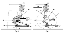
- the 3 and 4 show a further embodiment of a suspension according to the invention.
- the spring-damper strut 10 is here seen in front of the drive shaft 33 arranged (see direction of travel arrow 43). The remaining components remain unchanged.
- the spring-damper strut 10 in turn arranged obliquely to the wishbone 30 in side view of the suspension.
- the spring-damper strut 10 is arranged in front of or behind the drive shaft 33 depends on the particular application. Name, such an arrangement in combination with the inclination of the spring-damper strut 10 to the control arm 30 towards another way of reducing the height of the spring-strut leg support bearing 11, whereby the pedestrian protection improved and the hood can be reduced based on known suspension in height. In addition, much larger wheel movements (seen from the amount of a compression or rebound) can be achieved.
Landscapes
- Engineering & Computer Science (AREA)
- Mechanical Engineering (AREA)
- Vehicle Body Suspensions (AREA)
Abstract
Description
Die Erfindung betrifft eine Radaufhängung für ein Kraftfahrzeug der im Oberbegriff von Anspruch 1 genannten Art. Solche Radaufhängungen der bekannten McPherson-Bauweise kommen insbesondere bei Vorderradaufhängungen von Kraftfahrzeugen mit Vorderradantrieb zum Einsatz.The invention relates to a suspension for a motor vehicle referred to in the preamble of claim 1. Art Such suspensions of the known McPherson design are used in particular in front suspensions of motor vehicles with front-wheel drive.
Die
Die
Bei der Konzeption eingangs genannter Radaufhängungen sind mehrere Aspekte zu berücksichtigen. Zum einen ist es vorteilhaft, einen negativen Lenkrollradius vorzusehen. Unter Lenkrollradius versteht man den Abstand einer gedachten verlängerten Linie der Lenkdrehachse zur Mitte der Radaufstandsfläche. Beim Bremsen auf Fahrbahnen mit unterschiedlicher Reibhaftung der beiden Fahrzeugseiten ergibt sich bei negativem Lenkrollradius an der Vorderachse ein stabilisierender Effekt in Bezug auf die Gierbewegung des Fahrzeugs.When designing the aforementioned suspension, several aspects have to be considered. On the one hand, it is advantageous to provide a negative steering roller radius. Under steering roll radius is the distance of an imaginary extended line of the steering axis of rotation to the center of the Radaufstandsfläche. When braking on roads with different Reibhaftung the two sides of the vehicle results in a negative steering wheel radius on the front axle, a stabilizing effect in relation to the yaw motion of the vehicle.
Die
Der Erfindung liegt die Aufgabe zugrunde, eine Radaufhängung zu entwickeln, die die vorgenannten Nachteile vermeidet und eine stärkere Reduzierung der Höhe des Feder-Dämpferbeinstützlagers zuläßt, ohne die Vorteile der klassischen McPherson-Radaufhängung zu verlieren.The invention has for its object to develop a suspension that avoids the aforementioned disadvantages and allows a greater reduction in the height of the spring-shock absorber leg support bearing, without losing the benefits of the classic McPherson suspension.
Erfindungsgemäß wird die Aufgabe durch eine Radaufhängung mit den Merkmalen des Anspruchs 1 gelöst, wobei das Feder-Dämpferbein in Seitenansicht der Radaufhängung schräg zum Querlenker, also zum unteren Querlenker angeordnet ist, während die Lenkdrehachse durch die Lagerstelle des Querlenkers, also des unteren Querlenkers am Achsschenkelträger und den Kinematikpunkt des Feder-Dämpferbeinstützlagers bestimmt ist. Dadurch, dass das Feder-Dämpferbein in Seitenansicht der Radaufhängung schräg zum Querlenker angeordnet ist, kann die Bauhöhe des Feder-Dämpferbeinstützlagers erheblich reduziert werden. Hierdurch ist es möglich, einen besseren Fußgängerschutz sicherzustellen und auch die Motorhaube bzw. den Frontbereich des Fahrzeuges in Bezug auf das Design besser und flexibler anzupassen. In diesem Zusammenhang wird unter schräg verstanden, dass der Winkel zwischen der Symmetrieachse des Feder-Dämpferbeins und dem Querlenker nicht 90° beträgt. Der realisierbare Winkelbereich resultiert nicht zwingend aus der Kinematik der Radaufhängung und kann Werte von bis zu 30° erreichen. Durch die erfindungsgemäße Anordnung kann der vertikale Bauraumbedarf des Feder-Dämpferbeins um 10 bis 20%, beispielsweise bis zu 13,4 % gegenüber dem Stand der Technik reduziert werden.According to the invention the object is achieved by a suspension with the features of claim 1, wherein the spring-damper strut in side view of the suspension obliquely to the wishbone, so arranged to the lower arm, while the steering axis through the bearing point of the control arm, so the lower arm on the steering knuckle and the kinematic point of the spring-strut leg support bearing is determined. Characterized in that the spring-damper strut is arranged in side view of the suspension obliquely to the control arm, the overall height of the spring-shock absorber leg support bearing can be significantly reduced. This makes it possible to ensure better pedestrian protection and also to adapt the bonnet or the front of the vehicle in terms of the design better and more flexible. In this context, it is understood obliquely that the angle between the axis of symmetry of the spring-damper strut and the wishbone is not 90 °. The realizable angular range does not necessarily result from the kinematics of the suspension and can reach values of up to 30 °. The inventive arrangement of the vertical space requirement of the spring-damper strut can be reduced by 10 to 20%, for example, up to 13.4% over the prior art.
Besonders bevorzugt ist die Radaufhängung dabei so gestaltet, dass der Lenkrollradius negativ ist. Dies bringt die bereits erwähnten Vorteile bezüglich der Bremsstabilität mit sich.Particularly preferably, the suspension is designed so that the steering roller radius is negative. This brings the already mentioned advantages with regard to the braking stability.
Günstig im Sinne der Erfindung ist, wenn das Feder-Dämpferbein in Seitenansicht der Radaufhängung gesehen vor der Antriebswelle angeordnet ist, wobei auch eine in Seitenansicht der Radaufhängung gesehene Anordnung möglich ist, bei welcher das Feder-Dämpferbein hinter der Antriebswelle angeordnet ist.Favorable in the context of the invention is when the spring-damper strut seen in side view of the suspension is arranged in front of the drive shaft, which also seen in a side view of the suspension arrangement is possible in which the spring-damper strut is arranged behind the drive shaft.
Zweckmäßiger Weise ist das Feder-Dämpferbein nur an einer Stelle mit dem Achsschenkelträger bzw. mit dem Radträger verbunden, wobei die Verbindung bzw. Befestigung an einer oberen Stelle des Radträgers sinnvoll ist. Denkbar ist aber auch, noch eine zusätzliche Verbindung bzw. Befestigung des Feder-Dämpferbeins zum Achsschenkelträger bzw. Radträger vorzusehen, um gegebenenfalls die Steifigkeit bzw. Stabilität weiter zu verbessern.Conveniently, the spring-damper strut is connected only at one point with the stub axle or with the wheel carrier, wherein the connection or attachment to an upper position of the wheel carrier makes sense. It is also conceivable, however, to provide an additional connection or attachment of the spring-damper strut to the stub axle carrier or wheel carrier, in order to further improve the rigidity and stability, if necessary.
Weitere vorteilhafte Ausgestaltungen der Erfindung sind in den Unteransprüchen und der folgenden Figurenbeschreibung offenbart. Es zeigen:
- Fig.1
- eine Radaufhängung in einem ersten Ausführungsbeispiel in Vorderansicht,
- Fig. 2
- die Radaufhängung aus
Fig. 1 in Seitenansicht, - Fig.3
- eine Radaufhängung in einem zweiten Ausführungsbeispiel in Vorderansicht,
- Fig. 4
- die Radaufhängung aus
Fig. 3 in Seitenansicht.
- Fig.1
- a suspension in a first embodiment in front view,
- Fig. 2
- the suspension from
Fig. 1 in side view, - Figure 3
- a suspension in a second embodiment in front view,
- Fig. 4
- the suspension from
Fig. 3 in side view.
In den unterschiedlichen Figuren sind gleiche Teile stets mit denselben Bezugszeichen versehen, weswegen diese in der Regel auch nur einmal beschrieben werden.In the different figures, the same parts are always provided with the same reference numerals, which is why these are usually described only once.
Das Feder-Dämpferbein 10 ist hier im vorliegenden Ausführungsbeispiel nur an einer Stelle bzw. in einem Befestigungsbereich 42 mit dem Achsschenkelträger bzw. Radträger 20 verbunden. Zur Erhöhung der Stabilität kann auch sinnvoll sein, das Feder-Dämpferbein 10 an seinem unteren Ende 12 bzw. an seinem zum ersten Befestigungsbereich 42 tiefer gelegenen Befestigungspunkt bzw. -bereich noch ein zweites Mal am Achsschenkelträger bzw. Radträger 20 zu befestigen.The spring-
Aus
Die
Ob das Feder-Dämpferbein 10 vor oder hinter der Antriebswelle 33 angeordnet ist, hängt vom jeweiligen Anwendungsfall ab. Jedenfalls bietet eine solche Anordnung in Kombination mit der Schrägstellung des Feder-Dämpferbeins 10 zum Querlenker 30 hin eine weitere Möglichkeit der Reduzierung der Höhe des Feder-Dämpferbeinstützlagers 11, wodurch der Fußgängerschutz verbessert und die Motorhaube bezogen auf bekannte Radaufhängungen in der Höhe reduziert werden kann. Zudem können weitaus größere Radbewegungen (vom Betrag bei einem Ein- bzw. Ausfedern gesehen) erreicht werden.Whether the spring-
- 1010
- Feder-DämpferbeinSpring-damper strut
- 1111
- Kinematikpunkt des Feder-DämpferbeinstützlagersCinematic point of the spring shock absorber leg support bearing
- 1212
- Unteres Ende von 10Lower end of 10
- 2020
- Achsschenkelträger/RadträgerSteering knuckle / wheel carrier
- 2121
- Lagerstelledepository
- 3030
- Querlenkerwishbone
- 3131
- Eines Ende von 30One end of 30
- 3232
- Anderes Ende von 30Other end of 30
- 3333
- Antriebswelledrive shaft
- 4040
- Radnabewheel hub
- 4141
- Spurstangetie rod
- 4242
- Befestigungsbereich von 10 an 20Mounting range from 10 to 20
- 4343
- Fahrtrichtung (Pfeil)Direction of travel (arrow)
- A1A1
- LenkdrehachseSteering axis
- A2A2
- Schwenkachse von 30Pivot axis of 30
Claims (5)
dadurch gekennzeichnet, dass
die Lenkdrehachse (A1) durch die Lagerstelle (21) und den Kinematikpunkt des Feder-Dämpferbeinstützlagers (11) bestimmt ist und, dass das Feder-Dämpferbein (10) in Seitenansicht der Radaufhängung schräg zum Querlenker (30) angeordnet ist.Wheel suspension for a motor vehicle with a spring-damper strut (10), which is connectable to a stub axle (20), wherein a transverse link (30) is provided which is pivotally mounted at its one end (31) about an axis (A2) and which is articulated with its other end (32) to form a bearing point (21) on the stub axle (20),
characterized in that
the steering axis of rotation (A1) is determined by the bearing point (21) and the kinematic point of the spring-damper leg support bearing (11) and that the spring-damper strut (10) is arranged obliquely to the transverse link (30) in a side view of the wheel suspension.
dadurch gekennzeichnet, dass
das Feder-Dämpferbein (10) in Seitenansicht der Radaufhängung vor oder hinter der Antriebswelle (33) angeordnet ist.Wheel suspension according to claim 1,
characterized in that
the spring-damper strut (10) in side view of the suspension in front of or behind the drive shaft (33) is arranged.
dadurch gekennzeichnet, dass
das Feder-Dämpferbein (10) nur an einer Stelle mit dem Achsschenkelträger (20) verbunden ist.Wheel suspension according to claim 1 or 2,
characterized in that
the spring-damper strut (10) is connected to the steering knuckle carrier (20) only at one point.
dadurch gekennzeichnet, dass
das Feder-Dämpferbein (10) an seinem unteren Ende (12) einen zweiten Befestigungspunkt zum Achsschenkelträger (20) aufweist.Wheel suspension according to claim 1 or 2,
characterized in that
the spring-damper strut (10) at its lower end (12) has a second attachment point to the stub axle (20).
dadurch gekennzeichnet, dass
der Lenkrollradius negativ ist.Wheel suspension according to one of the preceding claims,
characterized in that
the steering wheel radius is negative.
Priority Applications (2)
| Application Number | Priority Date | Filing Date | Title |
|---|---|---|---|
| EP10186998A EP2441602A1 (en) | 2010-10-08 | 2010-10-08 | Wheel suspension with a spring-damper strut |
| CN2011203789938U CN202389141U (en) | 2010-10-08 | 2011-09-28 | Wheel suspension frame |
Applications Claiming Priority (1)
| Application Number | Priority Date | Filing Date | Title |
|---|---|---|---|
| EP10186998A EP2441602A1 (en) | 2010-10-08 | 2010-10-08 | Wheel suspension with a spring-damper strut |
Publications (1)
| Publication Number | Publication Date |
|---|---|
| EP2441602A1 true EP2441602A1 (en) | 2012-04-18 |
Family
ID=43662186
Family Applications (1)
| Application Number | Title | Priority Date | Filing Date |
|---|---|---|---|
| EP10186998A Withdrawn EP2441602A1 (en) | 2010-10-08 | 2010-10-08 | Wheel suspension with a spring-damper strut |
Country Status (2)
| Country | Link |
|---|---|
| EP (1) | EP2441602A1 (en) |
| CN (1) | CN202389141U (en) |
Cited By (2)
| Publication number | Priority date | Publication date | Assignee | Title |
|---|---|---|---|---|
| DE102013222443A1 (en) | 2013-11-05 | 2015-05-07 | Voith Patent Gmbh | Wheel suspension for a motor vehicle |
| DE102013222442A1 (en) | 2013-11-05 | 2015-05-07 | Voith Patent Gmbh | Wheel suspension for a motor vehicle |
Families Citing this family (6)
| Publication number | Priority date | Publication date | Assignee | Title |
|---|---|---|---|---|
| CN105015271A (en) * | 2015-07-23 | 2015-11-04 | 张家港市九鼎机械有限公司 | Front-and-rear axle structure of vehicle, and vehicle with same |
| CN106541986B (en) * | 2016-11-08 | 2019-10-01 | 同济大学 | A kind of double-crank transmission McPherson suspension line traffic control independent steering system |
| FR3060465B1 (en) * | 2016-12-21 | 2019-08-23 | Renault S.A.S | SUSPENSION AND DAMPING SYSTEM SUITABLE FOR THE FLOOR CONTROL OF A MOTOR VEHICLE |
| CN108556580A (en) * | 2018-02-02 | 2018-09-21 | 福建(泉州)哈工大工程技术研究院 | A kind of Mecanum wheel Omni-mobile platform independent suspension structure |
| JP2020111270A (en) * | 2019-01-16 | 2020-07-27 | トヨタ自動車株式会社 | Steering device and vehicle wheel mounting module including the same |
| FR3153793A1 (en) * | 2023-10-09 | 2025-04-11 | Renault S.A.S | Front structure of a motor vehicle |
Citations (11)
| Publication number | Priority date | Publication date | Assignee | Title |
|---|---|---|---|---|
| DE1505549A1 (en) * | 1966-02-23 | 1969-10-30 | Bayerische Motoren Werke Ag | Independent suspension of the steered wheels of motor vehicles, in particular passenger cars |
| DE2633402A1 (en) * | 1976-07-24 | 1978-01-26 | Opel Adam Ag | High stability independent suspension for road vehicles - has depressions in side of damper rod to accommodate track rod |
| DE2747561A1 (en) * | 1976-11-26 | 1978-06-01 | Gen Motors Corp | SINGLE WHEEL SUSPENSION FOR MOTOR VEHICLES |
| DE2829278A1 (en) * | 1978-07-04 | 1980-01-17 | Volkswagenwerk Ag | Stabilised suspension for front wheel drive car - has reaction links to counter braking and accelerating forces ensuring headlamp alignment |
| DE2945802A1 (en) | 1978-11-14 | 1980-05-22 | Renault | FRONT SUSPENSION FOR MOTOR VEHICLES |
| DE3005916A1 (en) | 1980-02-16 | 1981-09-03 | Daimler-Benz Ag, 7000 Stuttgart | WHEEL SUSPENSION, IN PARTICULAR A STEERED MOTOR VEHICLE FRONT AXLE |
| JPH0459404A (en) * | 1990-06-29 | 1992-02-26 | Nissan Motor Co Ltd | Rear suspension device |
| DE4413412A1 (en) | 1994-04-18 | 1995-10-19 | Daimler Benz Ag | omnibus |
| DE19509470A1 (en) * | 1995-03-16 | 1996-09-19 | Porsche Ag | Front wheel suspension for motor vehicle |
| DE10338045A1 (en) * | 2003-08-19 | 2005-03-10 | Volkswagen Ag | McPherson type front axle of vehicle, comprising shock absorber unit leaning backwards in relation to direction of motion |
| GB2468302A (en) * | 2009-03-03 | 2010-09-08 | Gordon Murray Design Ltd | Vehicle suspension |
-
2010
- 2010-10-08 EP EP10186998A patent/EP2441602A1/en not_active Withdrawn
-
2011
- 2011-09-28 CN CN2011203789938U patent/CN202389141U/en not_active Expired - Fee Related
Patent Citations (12)
| Publication number | Priority date | Publication date | Assignee | Title |
|---|---|---|---|---|
| DE1505549A1 (en) * | 1966-02-23 | 1969-10-30 | Bayerische Motoren Werke Ag | Independent suspension of the steered wheels of motor vehicles, in particular passenger cars |
| DE2633402A1 (en) * | 1976-07-24 | 1978-01-26 | Opel Adam Ag | High stability independent suspension for road vehicles - has depressions in side of damper rod to accommodate track rod |
| DE2747561A1 (en) * | 1976-11-26 | 1978-06-01 | Gen Motors Corp | SINGLE WHEEL SUSPENSION FOR MOTOR VEHICLES |
| DE2829278A1 (en) * | 1978-07-04 | 1980-01-17 | Volkswagenwerk Ag | Stabilised suspension for front wheel drive car - has reaction links to counter braking and accelerating forces ensuring headlamp alignment |
| DE2945802A1 (en) | 1978-11-14 | 1980-05-22 | Renault | FRONT SUSPENSION FOR MOTOR VEHICLES |
| US4341396A (en) | 1978-11-14 | 1982-07-27 | Regie Nationale Des Usines Renault | Front axle assembly for automobile |
| DE3005916A1 (en) | 1980-02-16 | 1981-09-03 | Daimler-Benz Ag, 7000 Stuttgart | WHEEL SUSPENSION, IN PARTICULAR A STEERED MOTOR VEHICLE FRONT AXLE |
| JPH0459404A (en) * | 1990-06-29 | 1992-02-26 | Nissan Motor Co Ltd | Rear suspension device |
| DE4413412A1 (en) | 1994-04-18 | 1995-10-19 | Daimler Benz Ag | omnibus |
| DE19509470A1 (en) * | 1995-03-16 | 1996-09-19 | Porsche Ag | Front wheel suspension for motor vehicle |
| DE10338045A1 (en) * | 2003-08-19 | 2005-03-10 | Volkswagen Ag | McPherson type front axle of vehicle, comprising shock absorber unit leaning backwards in relation to direction of motion |
| GB2468302A (en) * | 2009-03-03 | 2010-09-08 | Gordon Murray Design Ltd | Vehicle suspension |
Cited By (5)
| Publication number | Priority date | Publication date | Assignee | Title |
|---|---|---|---|---|
| DE102013222443A1 (en) | 2013-11-05 | 2015-05-07 | Voith Patent Gmbh | Wheel suspension for a motor vehicle |
| DE102013222442A1 (en) | 2013-11-05 | 2015-05-07 | Voith Patent Gmbh | Wheel suspension for a motor vehicle |
| WO2015067638A2 (en) | 2013-11-05 | 2015-05-14 | Voith Patent Gmbh | Wheel suspension for a motor vehicle |
| DE102013222442B4 (en) * | 2013-11-05 | 2016-12-15 | Brist Axle Systems S.R.L. | Wheel suspension for a steerable drive wheel in a motor vehicle |
| US10124639B2 (en) | 2013-11-05 | 2018-11-13 | Brist Axle Systems S.R.L. | Wheel suspension for a motor vehicle |
Also Published As
| Publication number | Publication date |
|---|---|
| CN202389141U (en) | 2012-08-22 |
Similar Documents
| Publication | Publication Date | Title |
|---|---|---|
| DE102016220786B4 (en) | Rear suspension for motor vehicles | |
| DE4313978A1 (en) | Suspension arrangement for steered wheel on vehicle - has upper and lower arms swivel mounted on body and uses stabiliser and damping element to avoid deformation of transverse connecting member | |
| DE102012011865A1 (en) | Arm | |
| EP2246204B1 (en) | Independent wheel suspension | |
| DE102006016762A1 (en) | Steering knuckle for a vehicle | |
| DE102012011868A1 (en) | Arm | |
| DE102011018276A1 (en) | Wheel suspension for an axle of a motor vehicle | |
| WO2014124721A1 (en) | Wheel suspension for a motor vehicle | |
| DE102012022889A1 (en) | Stabilizer arrangement for a suspension of motor vehicles | |
| DE102015201338A1 (en) | Trailing arm axle for suspension of a motor vehicle wheel | |
| EP1346854B1 (en) | Motor vehicle wheel suspension | |
| DE102022102115A1 (en) | Wheel suspension, an axle and a vehicle | |
| DE60306730T2 (en) | Steering device for the carrying device of the rear hub in motor vehicles | |
| DE102015212580A1 (en) | suspension structure | |
| EP4598758A1 (en) | Wheel suspension system for a vehicle wheel of a motor vehicle, and motor vehicle | |
| DE102015206443A1 (en) | Suspension for a vehicle | |
| DE102010061018A1 (en) | Wheel suspension of a motor vehicle | |
| EP2874831A1 (en) | Wheel suspension for the rear axle of a vehicle | |
| DE202017100164U1 (en) | Rear suspension for motor vehicles | |
| DE102019200214A1 (en) | Steerable twist link axle for a motor vehicle, trailing arm and motor vehicle | |
| DE102018207616B4 (en) | Wheel suspension for a motor vehicle | |
| WO2024110110A1 (en) | Wheel suspension for a motor vehicle and corresponding motor vehicle | |
| DE102012221699A1 (en) | Wheel suspension i.e. double wishbone wheel suspension, for motor car, has arm parts connected by connection joint between structure-side and carrier-side joints, and actuators for pivoting structure-side and connection joints, respectively | |
| DE102012011864A1 (en) | Independent wheel suspension for supporting e.g. rear wheel of motor vehicle on bodywork of motor vehicle, has coupling arm coupled with wheel support over upper coupling bearing, and stabilizer coupled with coupling arm over pendulum bar | |
| DE102011006555A1 (en) | Wheel suspension i.e. front wheel suspension, for guided and unguided axels of e.g. motor vehicle, has wheel control device provided with two shock absorbers whose longitudinal axes enclose acute angle |
Legal Events
| Date | Code | Title | Description |
|---|---|---|---|
| PUAI | Public reference made under article 153(3) epc to a published international application that has entered the european phase |
Free format text: ORIGINAL CODE: 0009012 |
|
| AK | Designated contracting states |
Kind code of ref document: A1 Designated state(s): AL AT BE BG CH CY CZ DE DK EE ES FI FR GB GR HR HU IE IS IT LI LT LU LV MC MK MT NL NO PL PT RO RS SE SI SK SM TR |
|
| AX | Request for extension of the european patent |
Extension state: BA ME |
|
| STAA | Information on the status of an ep patent application or granted ep patent |
Free format text: STATUS: THE APPLICATION HAS BEEN WITHDRAWN |
|
| 18W | Application withdrawn |
Effective date: 20120503 |