EP2441679A2 - Führungsvorrichtung und Verfahren zur Herstellung einer versteiften Platte - Google Patents
Führungsvorrichtung und Verfahren zur Herstellung einer versteiften Platte Download PDFInfo
- Publication number
- EP2441679A2 EP2441679A2 EP12150821A EP12150821A EP2441679A2 EP 2441679 A2 EP2441679 A2 EP 2441679A2 EP 12150821 A EP12150821 A EP 12150821A EP 12150821 A EP12150821 A EP 12150821A EP 2441679 A2 EP2441679 A2 EP 2441679A2
- Authority
- EP
- European Patent Office
- Prior art keywords
- stringer
- datum part
- base
- datum
- side stop
- Prior art date
- Legal status (The legal status is an assumption and is not a legal conclusion. Google has not performed a legal analysis and makes no representation as to the accuracy of the status listed.)
- Granted
Links
Images







Classifications
-
- B—PERFORMING OPERATIONS; TRANSPORTING
- B64—AIRCRAFT; AVIATION; COSMONAUTICS
- B64F—GROUND OR AIRCRAFT-CARRIER-DECK INSTALLATIONS SPECIALLY ADAPTED FOR USE IN CONNECTION WITH AIRCRAFT; DESIGNING, MANUFACTURING, ASSEMBLING, CLEANING, MAINTAINING OR REPAIRING AIRCRAFT, NOT OTHERWISE PROVIDED FOR; HANDLING, TRANSPORTING, TESTING OR INSPECTING AIRCRAFT COMPONENTS, NOT OTHERWISE PROVIDED FOR
- B64F5/00—Designing, manufacturing, assembling, cleaning, maintaining or repairing aircraft, not otherwise provided for; Handling, transporting, testing or inspecting aircraft components, not otherwise provided for
- B64F5/10—Manufacturing or assembling aircraft, e.g. jigs therefor
-
- B—PERFORMING OPERATIONS; TRANSPORTING
- B21—MECHANICAL METAL-WORKING WITHOUT ESSENTIALLY REMOVING MATERIAL; PUNCHING METAL
- B21D—WORKING OR PROCESSING OF SHEET METAL OR METAL TUBES, RODS OR PROFILES WITHOUT ESSENTIALLY REMOVING MATERIAL; PUNCHING METAL
- B21D39/00—Application of procedures in order to connect objects or parts, e.g. coating with sheet metal otherwise than by plating; Tube expanders
-
- B—PERFORMING OPERATIONS; TRANSPORTING
- B33—ADDITIVE MANUFACTURING TECHNOLOGY
- B33Y—ADDITIVE MANUFACTURING, i.e. MANUFACTURING OF THREE-DIMENSIONAL [3D] OBJECTS BY ADDITIVE DEPOSITION, ADDITIVE AGGLOMERATION OR ADDITIVE LAYERING, e.g. BY 3D PRINTING, STEREOLITHOGRAPHY OR SELECTIVE LASER SINTERING
- B33Y80/00—Products made by additive manufacturing
-
- Y—GENERAL TAGGING OF NEW TECHNOLOGICAL DEVELOPMENTS; GENERAL TAGGING OF CROSS-SECTIONAL TECHNOLOGIES SPANNING OVER SEVERAL SECTIONS OF THE IPC; TECHNICAL SUBJECTS COVERED BY FORMER USPC CROSS-REFERENCE ART COLLECTIONS [XRACs] AND DIGESTS
- Y02—TECHNOLOGIES OR APPLICATIONS FOR MITIGATION OR ADAPTATION AGAINST CLIMATE CHANGE
- Y02P—CLIMATE CHANGE MITIGATION TECHNOLOGIES IN THE PRODUCTION OR PROCESSING OF GOODS
- Y02P70/00—Climate change mitigation technologies in the production process for final industrial or consumer products
- Y02P70/50—Manufacturing or production processes characterised by the final manufactured product
-
- Y—GENERAL TAGGING OF NEW TECHNOLOGICAL DEVELOPMENTS; GENERAL TAGGING OF CROSS-SECTIONAL TECHNOLOGIES SPANNING OVER SEVERAL SECTIONS OF THE IPC; TECHNICAL SUBJECTS COVERED BY FORMER USPC CROSS-REFERENCE ART COLLECTIONS [XRACs] AND DIGESTS
- Y10—TECHNICAL SUBJECTS COVERED BY FORMER USPC
- Y10T—TECHNICAL SUBJECTS COVERED BY FORMER US CLASSIFICATION
- Y10T29/00—Metal working
- Y10T29/49—Method of mechanical manufacture
- Y10T29/49616—Structural member making
- Y10T29/49622—Vehicular structural member making
-
- Y—GENERAL TAGGING OF NEW TECHNOLOGICAL DEVELOPMENTS; GENERAL TAGGING OF CROSS-SECTIONAL TECHNOLOGIES SPANNING OVER SEVERAL SECTIONS OF THE IPC; TECHNICAL SUBJECTS COVERED BY FORMER USPC CROSS-REFERENCE ART COLLECTIONS [XRACs] AND DIGESTS
- Y10—TECHNICAL SUBJECTS COVERED BY FORMER USPC
- Y10T—TECHNICAL SUBJECTS COVERED BY FORMER US CLASSIFICATION
- Y10T29/00—Metal working
- Y10T29/49—Method of mechanical manufacture
- Y10T29/49616—Structural member making
- Y10T29/49623—Static structure, e.g., a building component
- Y10T29/49629—Panel
-
- Y—GENERAL TAGGING OF NEW TECHNOLOGICAL DEVELOPMENTS; GENERAL TAGGING OF CROSS-SECTIONAL TECHNOLOGIES SPANNING OVER SEVERAL SECTIONS OF THE IPC; TECHNICAL SUBJECTS COVERED BY FORMER USPC CROSS-REFERENCE ART COLLECTIONS [XRACs] AND DIGESTS
- Y10—TECHNICAL SUBJECTS COVERED BY FORMER USPC
- Y10T—TECHNICAL SUBJECTS COVERED BY FORMER US CLASSIFICATION
- Y10T29/00—Metal working
- Y10T29/49—Method of mechanical manufacture
- Y10T29/49826—Assembling or joining
- Y10T29/49895—Associating parts by use of aligning means [e.g., use of a drift pin or a "fixture"]
-
- Y—GENERAL TAGGING OF NEW TECHNOLOGICAL DEVELOPMENTS; GENERAL TAGGING OF CROSS-SECTIONAL TECHNOLOGIES SPANNING OVER SEVERAL SECTIONS OF THE IPC; TECHNICAL SUBJECTS COVERED BY FORMER USPC CROSS-REFERENCE ART COLLECTIONS [XRACs] AND DIGESTS
- Y10—TECHNICAL SUBJECTS COVERED BY FORMER USPC
- Y10T—TECHNICAL SUBJECTS COVERED BY FORMER US CLASSIFICATION
- Y10T29/00—Metal working
- Y10T29/49—Method of mechanical manufacture
- Y10T29/49826—Assembling or joining
- Y10T29/49895—Associating parts by use of aligning means [e.g., use of a drift pin or a "fixture"]
- Y10T29/49899—Associating parts by use of aligning means [e.g., use of a drift pin or a "fixture"] by multiple cooperating aligning means
-
- Y—GENERAL TAGGING OF NEW TECHNOLOGICAL DEVELOPMENTS; GENERAL TAGGING OF CROSS-SECTIONAL TECHNOLOGIES SPANNING OVER SEVERAL SECTIONS OF THE IPC; TECHNICAL SUBJECTS COVERED BY FORMER USPC CROSS-REFERENCE ART COLLECTIONS [XRACs] AND DIGESTS
- Y10—TECHNICAL SUBJECTS COVERED BY FORMER USPC
- Y10T—TECHNICAL SUBJECTS COVERED BY FORMER US CLASSIFICATION
- Y10T29/00—Metal working
- Y10T29/53—Means to assemble or disassemble
Definitions
- the present invention relates to a method and apparatus for manufacturing a stiffened panel, and a datum part for use in such a method.
- a stringer tang is a tab of metal that extends longitudinally from the end of a stringer. This tab is used as a reference datum and has a bolt-hole therein. The tang is secured to a reference point on a jig (which is a known datum with respect to a panel) and hence locates the stringer spatially in relation to the panel.
- the stringer tang itself allows the stringer to be bolted to and structurally supported by the jig. Thus, the stringer is located in the correct position in relation to the panel.
- the stringers are then riveted or fastened to the panel whereupon the entire assembly is released from the jig by removing the panel plus the stringers from the jig.
- the tangs are then cut off and the areas around them are treated to remove any protuberances or rough edges. This is a time consuming and laborious process.
- a first aspect of the invention provides a datum part comprising a base; and a pair of side stop blocks extending from the base and positioned towards the periphery of the base; wherein one of the side stop blocks is formed with a resilient spring.
- a second aspect of the invention provides a method of manufacturing a stiffened panel, the method comprising: holding the panel with a jig; holding a datum part with the jig; engaging the panel and the datum part with a stringer; and joining the stringer to the panel, wherein the datum part comprises a base and a pair of side stop blocks extending from the base and positioned towards the periphery of the base, wherein one of the side stop blocks is formed with a resilient spring, and wherein the method further comprises: engaging the stringer with side stop blocks; and flexing the resilient spring to account for variation in width of the stringer.
- the second aspect of the invention removes the requirement of stringer tangs. That is, the datum part enables the stringer to be located in the correct position in relation to the panel without requiring the stringer to be formed with a tang.
- Datum blocks with different shapes and sizes can be used in the manufacture of a single panel, each tailor-made to fit a respective stringer.
- the method comprises: holding a plurality of datum parts with the jig, at least two of the datum parts having a different shape or size; engaging the panel with a plurality of stringers; engaging each datum part with a respective one of the stringers; and joining the stringers to the panel.
- the datum part further comprises one or more height stops extending from the base by a first distance, wherein the side stop blocks extend from the base by a second distance greater than the first distance.
- the datum part Preferably an additive process is used to form the datum part.
- the shape of each layer can be selected to enable the shape or size of the datum part to be optimised.
- each layer is grown by directing energy and/or material from a head to selected parts of a build region.
- the head and the build region may remain stationary during the growth process: for example the head may have a fixed array of lasers and/or nozzles which extend over the entire build region and are modulated as required to directing energy and/or material to selected parts of the build region.
- the method further comprises causing relative movement between the head and the build region. Preferably this relative movement is caused by moving the head, but it will appreciated that the relative movement may be caused by moving the component or by a combined movement of both parts.
- Various additive fabrication techniques may be used, including techniques in which the head directs material to selected parts of the build region, and techniques in which a series of beds of material are deposited on the build region and the head directs energy to selected parts of each bed.
- Examples of the former include fused deposition modelling (in which the head extrudes hot plastic through a nozzle) and powder feed fabrication (in which a laser beam directs energy to fuse a powdered material as it is delivered to the build region). Advantages of these methods are that:
- stereolithography in which a laser is used to cure selected parts of a bed of liquid photopolymer
- powder bed fabrication in which a series of beds of powder are deposited on the build region and selected parts of each bed are fused by a laser.
- the datum part is formed by fusing a powder, for instance in a powder bed process or a powder feed process.
- the stringer extends lengthwise between a pair of end faces, and the datum part engages one of the end faces of the stringer.
- Figure 1 shows a step in the assembly of a stiffened panel which forms the upper or lower skin of a wing box.
- the wing box comprises an upper and lower skin, each skin carrying a series of stringers on its inner surface which run in a span-wise direction along the wing box.
- a series of ribs run in a chord wise direction across the wing box and are joined to the upper and lower skins.
- Each stringer has an inboard end (conventionally known as a "stringer run-out”) adjacent to the inboard rib (which is conventionally known as "rib 1”) and an outboard end.
- Figure 1 shows the inboard run-outs of three stringers 1-3, a profile board 4 and a skin 5.
- the profile board 4 forms part of a jig, and has the same shape and size as "rib 1" of the wing box.
- the skin 5 is held by another part (not shown) of the jig.
- a datum part 10 is held by the profile board 4. Note that the datum parts are not shown in Figure 1 .
- a vertical plate 11 of an L-shaped bracket is secured to the profile board 4 by fasteners 12, and the datum part 10 is secured to a horizontal plate 13 of the L-shaped bracket by fasteners 14.
- a plate 20 carries three stringer height stop blocks 21, a pair of resilient clips 22, and four stringer side stop blocks 23-26 at the periphery of the plate 20.
- the left-hand stop blocks 23 and 25 are formed with resilient springs 23a and 25a.
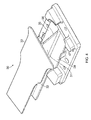
- the stringer 30 comprises a web 31, a pair of upper flanges 32,33 and a pair of lower flanges 34,35. As shown most clearly in Figure 4 , the upper flanges 32,33 are terminated short of the end of the stringer, and the web 31 has a tapered edge 36 extending beyond the end of the upper flanges 32,33.
- the lower faces of the lower flanges 34,35 engage the stringer height stop blocks 21, and the sides and ends of the lower flanges 34,35 engage the nesting faces of the four stringer side stop blocks 23-26, as well as being secured against vertical movement by the clips 22.
- the height stop blocks 21 extend from the plate 20 by a first distance, and the side stop blocks 23-26 extending from the base by a second distance greater than the first distance.
- FIG 5 is an enlarged perspective view showing one of the clips 22 in detail.
- the other clip 22 has a similar form and works in a similar manner.
- the clip 22 has a cantilever arm 27, and a projecting nose configured with a curved upper edge 28 and sharp lower edge 29.
- the edge of the flange 34 engages the curved upper edge 28 and the arm 27 bends back.
- the clip snaps back resiliently into place to provide a cantilever snap-fit joint which locks the stringer securely against vertical movement as shown in Figure 4 .
- the resilient springs 23a,25a can flex to account for slight variations in width of the stringer.
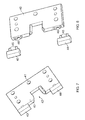
- Figure 7 shows a nest plate 40.
- a series of such nest plates are held by the jig at spaced locations along the length of the stringer.
- the nest plate comprises a series of holes 41 which receive fasteners (not shown) for fixing the nest plate to the jig, and a slot 42 in an upper edge of the plate.
- the upper edge of the plate also carries a pair of renewable tips 43,44.
- the nest plates 40 are moved towards the stringer by the jig, until the upper flanges of the stringer are received in the slot 42, and each lower flange 34,35 is engaged by a respective one of the renewable tips 43,44 which press the lower flanges 34,35 against the skin.
- a resilient spring 47 is provided on one side of the slot 42. The spring 47 is separated from the body of the nest plate by a gap 48, and can flex to account for slight variations in width of the stringer.
- each renewable tip 43,44 has a pair of pegs 45 which are received in holes 46 in the upper edge of the nest plate 40. This enables the tips 43,44 to be removed and replaced by new tips in the event that they become flattened over time due to the clamping pressure. Furthermore, the tips 43,44 are formed by a harder material than the nest plate 40 to provide increased resistance to such flattening.
- Figure 9 shows another part of the stringer 30.
- the skin is relatively thin, so a different method of interfacing with the jig is required.
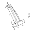
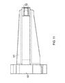
- a datum part shown in detail in Figures 10 and 11 , is held by a profile board (not shown) of the jig.
- the datum part comprises an arm 51 which extends from a block 50 and carries a pair of clips 52 at its distal end which grip the sides of the lower flanges as shown in Figure 9 .
- the upper edge of the block 50 has a pair of blocks 53, one formed with a resilient spring 53a which can flex to account for slight variations in width of the stringer..
- FIG. 12 An alternative datum part 60 is shown in Figure 12 .
- the datum part 60 does not fall within the scope of the present application.
- the datum part has an end stop 61 which engages an end edge of the lower flanges of the stringer, and the sides of the stringer are engaged by resilient springs 62-65. Note that no clips are provided with this datum block.
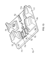
- a further alternative datum part 70 is shown in Figure 13 .
- the datum part 70 comprises a plate 71 carrying two stringer height stop blocks 72, a pair of resilient clips 73, and four stringer side stop blocks 75-77.
- the stop blocks 76 and 77 are formed with resilient springs 76a and 77a.
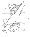
- the inboard end of a stringer 80 is fitted to the datum part.
- the profile board 81 represents "rib 1" of the wing - that is, the inboard rib.
- the stringers After the stringers have been fitted to the various datum parts 10,50,60,70 and the nest plates 40 have been clamped in place, then the stringers are joined along their length to the skin by fasteners (not shown).
- the datum parts 10,50,60,70 ensure that the stringers are held against the skin by the jig in precisely the correct position before the fasteners are fitted.
- the datum parts 10,50,60,70 and nest plates 40 are each grown in a series of layers by a powder bed additive manufacturing system shown in Figure 15 .
- the powder bed system grows the part by scanning a laser head laterally across a powder bed and directing the laser to selected parts of the powder bed. More specifically, the system comprises a pair of feed containers 90, 91 containing powdered metallic material such as powdered Titanium.
- a roller 92 picks up powder from one of the feed containers (in the example of Figure 15 , the roller 92 is picking up powder from the right hand feed container 91) and rolls a continuous bed of powder over a support member 93.
- a laser head 94 then scans over the powder bed, and a laser beam from the head is turned on and off under the control of computer-aided design (CAD) model of the part, to melt the powder in a desired two-dimensional pattern.
- the support member 93 then moves down by a small distance (typically of the order of 0.1mm) to prepare for growth of the next layer. After a pause for the melted powder to solidify, the roller 92 proceeds to roll another layer of powder over support member 93 in preparation for sintering.
- a sintered part 95 is constructed, supported by unconsolidated powder parts 96. After the part has been completed, it is removed from the support member 93 and the unconsolidated powder 96 is recycled before being returned to the feed containers 90, 91.
- the additive process shown in Figure 15 provides a convenient method of manufacturing the datum parts 10,50,60,70 and nest plates 40 in precisely the right shape and size for their intended purpose.
- Different datum parts can be made by simply changing the CAD model. This enables the same jig to be used to manufacture a variety of different panel designs, as well as giving the ability of using datum blocks with different shapes and sizes in the manufacture of a single panel, each tailor-made to fit a respective stringer.
Landscapes
- Engineering & Computer Science (AREA)
- Manufacturing & Machinery (AREA)
- Transportation (AREA)
- Aviation & Aerospace Engineering (AREA)
- Mechanical Engineering (AREA)
- Laminated Bodies (AREA)
- Joining Of Building Structures In Genera (AREA)
- Devices For Post-Treatments, Processing, Supply, Discharge, And Other Processes (AREA)
- Moulding By Coating Moulds (AREA)
- Finishing Walls (AREA)
Applications Claiming Priority (2)
| Application Number | Priority Date | Filing Date | Title |
|---|---|---|---|
| GBGB0710349.2A GB0710349D0 (en) | 2007-05-31 | 2007-05-31 | Method of manufacturing a stiffened panel |
| EP08750766A EP2148816B1 (de) | 2007-05-31 | 2008-05-23 | Verfahren und vorrichtung zur herstellung einer versteiften platte |
Related Parent Applications (2)
| Application Number | Title | Priority Date | Filing Date |
|---|---|---|---|
| EP08750766.1 Division | 2008-05-23 | ||
| EP08750766A Division EP2148816B1 (de) | 2007-05-31 | 2008-05-23 | Verfahren und vorrichtung zur herstellung einer versteiften platte |
Publications (3)
| Publication Number | Publication Date |
|---|---|
| EP2441679A2 true EP2441679A2 (de) | 2012-04-18 |
| EP2441679A3 EP2441679A3 (de) | 2013-02-13 |
| EP2441679B1 EP2441679B1 (de) | 2015-07-01 |
Family
ID=38289569
Family Applications (2)
| Application Number | Title | Priority Date | Filing Date |
|---|---|---|---|
| EP12150821.2A Not-in-force EP2441679B1 (de) | 2007-05-31 | 2008-05-23 | Führungsvorrichtung und Verfahren zur Herstellung einer versteiften Platte |
| EP08750766A Not-in-force EP2148816B1 (de) | 2007-05-31 | 2008-05-23 | Verfahren und vorrichtung zur herstellung einer versteiften platte |
Family Applications After (1)
| Application Number | Title | Priority Date | Filing Date |
|---|---|---|---|
| EP08750766A Not-in-force EP2148816B1 (de) | 2007-05-31 | 2008-05-23 | Verfahren und vorrichtung zur herstellung einer versteiften platte |
Country Status (11)
| Country | Link |
|---|---|
| US (1) | US8752294B2 (de) |
| EP (2) | EP2441679B1 (de) |
| JP (1) | JP5497637B2 (de) |
| KR (1) | KR20080105960A (de) |
| CN (1) | CN101674986B (de) |
| AT (1) | ATE545582T1 (de) |
| BR (1) | BRPI0812017A2 (de) |
| CA (1) | CA2686127C (de) |
| GB (1) | GB0710349D0 (de) |
| RU (1) | RU2465178C2 (de) |
| WO (1) | WO2008146034A2 (de) |
Families Citing this family (4)
| Publication number | Priority date | Publication date | Assignee | Title |
|---|---|---|---|---|
| GB0710349D0 (en) * | 2007-05-31 | 2007-07-11 | Airbus Uk Ltd | Method of manufacturing a stiffened panel |
| US9614430B2 (en) * | 2014-02-26 | 2017-04-04 | Fsp Technology Inc. | Inverting apparatus and AC power system using the same |
| US10052670B2 (en) | 2015-09-11 | 2018-08-21 | Triumph Aerostructures, Llc | Stringer forming device and methods of using the same |
| CN110860613B (zh) * | 2019-11-19 | 2020-10-09 | 燕山大学 | 大型异型管材微铸轧增材制造的内腔近净成型装置 |
Family Cites Families (25)
| Publication number | Priority date | Publication date | Assignee | Title |
|---|---|---|---|---|
| JPS58143075U (ja) * | 1982-03-16 | 1983-09-27 | トヨタ自動車株式会社 | 板金部品の位置決め固定装置 |
| DE3219151A1 (de) | 1982-05-21 | 1983-11-24 | Gross & Froelich GmbH, 7000 Stuttgart | Spannvorrichtung |
| JPS59109587A (ja) | 1982-12-16 | 1984-06-25 | Nippon Steel Corp | コ−クス炉装入炭の乾燥予熱輸送装置 |
| JPS59109587U (ja) * | 1983-01-17 | 1984-07-24 | 日産自動車株式会社 | ゲ−ジプレ−ト |
| JPS59185093U (ja) * | 1983-05-26 | 1984-12-08 | 三菱重工業株式会社 | 板状部材と骨材との組立治具 |
| US5033178A (en) | 1988-07-06 | 1991-07-23 | The Boeing Company | Assembly jig and method for making wing panels |
| US4894903A (en) | 1988-07-06 | 1990-01-23 | The Boeing Company | Assembly jig and method for making wing panels |
| US5135695A (en) | 1989-12-04 | 1992-08-04 | Board Of Regents The University Of Texas System | Positioning, focusing and monitoring of gas phase selective beam deposition |
| SU1777297A1 (ru) * | 1990-02-12 | 1997-05-20 | Обнинское научно-производственное объединение "Технология" | Панель из композиционного материала и способ ее изготовления |
| US5341556A (en) | 1991-06-28 | 1994-08-30 | The United States Of America As Represented By The Secretary Of The Air Force | Method and apparatus for manufacture of reinforced panels |
| RU2067543C1 (ru) * | 1992-04-14 | 1996-10-10 | Акционерное общество открытого типа "Таганрогская авиация" | Устройство для сборки агрегатов летательных аппаратов |
| US5367595A (en) | 1993-07-15 | 1994-11-22 | General Motors Corporation | Fiber optic connector for connecting a fiber optic harness to an optical device |
| US5906863A (en) | 1994-08-08 | 1999-05-25 | Lombardi; John | Methods for the preparation of reinforced three-dimensional bodies |
| JP3144317B2 (ja) | 1996-09-12 | 2001-03-12 | トヨタ自動車株式会社 | 積層製造方法 |
| CN1051520C (zh) * | 1996-10-07 | 2000-04-19 | 王新云 | 飞行器的预应力结构及制造方法 |
| US6143378A (en) | 1998-05-12 | 2000-11-07 | Sandia Corporation | Energetic additive manufacturing process with feed wire |
| US6410105B1 (en) * | 1998-06-30 | 2002-06-25 | Jyoti Mazumder | Production of overhang, undercut, and cavity structures using direct metal depostion |
| US6200514B1 (en) | 1999-02-09 | 2001-03-13 | Baker Hughes Incorporated | Process of making a bit body and mold therefor |
| US6855099B2 (en) * | 2001-10-31 | 2005-02-15 | The Boeing Company | Manufacturing system for aircraft structures and other large structures |
| US7076856B2 (en) | 2002-11-14 | 2006-07-18 | The Boeing Company | Adjustable system and method for supporting and joining structural members |
| GB2399049B (en) | 2003-03-05 | 2006-01-18 | Stour Prec Tools Ltd | Composite structural component and method |
| GB2405119B (en) | 2003-08-01 | 2007-08-01 | Martin Gibbons | A clamp for holding a door to be worked on |
| DE10342880A1 (de) | 2003-09-15 | 2005-04-14 | Trumpf Werkzeugmaschinen Gmbh + Co. Kg | Substratplatte |
| GB0519364D0 (en) | 2005-09-22 | 2005-11-02 | Airbus Uk Ltd | Assembly of aircraft components |
| GB0710349D0 (en) * | 2007-05-31 | 2007-07-11 | Airbus Uk Ltd | Method of manufacturing a stiffened panel |
-
2007
- 2007-05-31 GB GBGB0710349.2A patent/GB0710349D0/en not_active Ceased
- 2007-10-25 KR KR1020070108029A patent/KR20080105960A/ko not_active Ceased
-
2008
- 2008-05-23 JP JP2010509900A patent/JP5497637B2/ja not_active Expired - Fee Related
- 2008-05-23 AT AT08750766T patent/ATE545582T1/de active
- 2008-05-23 WO PCT/GB2008/050371 patent/WO2008146034A2/en not_active Ceased
- 2008-05-23 RU RU2009145627/11A patent/RU2465178C2/ru not_active IP Right Cessation
- 2008-05-23 US US12/451,227 patent/US8752294B2/en not_active Expired - Fee Related
- 2008-05-23 CA CA2686127A patent/CA2686127C/en not_active Expired - Fee Related
- 2008-05-23 CN CN200880014877.9A patent/CN101674986B/zh not_active Expired - Fee Related
- 2008-05-23 EP EP12150821.2A patent/EP2441679B1/de not_active Not-in-force
- 2008-05-23 EP EP08750766A patent/EP2148816B1/de not_active Not-in-force
- 2008-05-23 BR BRPI0812017-0A2A patent/BRPI0812017A2/pt not_active IP Right Cessation
Non-Patent Citations (1)
| Title |
|---|
| None |
Also Published As
| Publication number | Publication date |
|---|---|
| JP5497637B2 (ja) | 2014-05-21 |
| EP2148816A2 (de) | 2010-02-03 |
| WO2008146034A2 (en) | 2008-12-04 |
| JP2010527847A (ja) | 2010-08-19 |
| KR20080105960A (ko) | 2008-12-04 |
| EP2441679A3 (de) | 2013-02-13 |
| CA2686127A1 (en) | 2008-12-04 |
| US20100170165A1 (en) | 2010-07-08 |
| US8752294B2 (en) | 2014-06-17 |
| RU2465178C2 (ru) | 2012-10-27 |
| CN101674986A (zh) | 2010-03-17 |
| GB0710349D0 (en) | 2007-07-11 |
| ATE545582T1 (de) | 2012-03-15 |
| EP2148816B1 (de) | 2012-02-15 |
| BRPI0812017A2 (pt) | 2014-11-18 |
| WO2008146034A3 (en) | 2009-05-07 |
| EP2441679B1 (de) | 2015-07-01 |
| CA2686127C (en) | 2016-05-03 |
| CN101674986B (zh) | 2015-11-25 |
| RU2009145627A (ru) | 2011-07-10 |
Similar Documents
| Publication | Publication Date | Title |
|---|---|---|
| US11731355B2 (en) | System and method for automated successive three-dimensional printing | |
| EP2441679B1 (de) | Führungsvorrichtung und Verfahren zur Herstellung einer versteiften Platte | |
| US6441338B1 (en) | Rapid manufacturing of steel rule dies and other 3-dimensional products, apparatus, process and products | |
| Dwivedi et al. | Automated torch path planning using polygon subdivision for solid freeform fabrication based on welding | |
| EP3431211B1 (de) | Verfahren zur herstellung von hybridartikeln | |
| DE10112629B4 (de) | Verfahren und Einrichtung zur variablen Herstellung von Laminatstrukturen | |
| DE69116662T2 (de) | Verfahren und Vorrichtung zur Herstellung dreidimensionaler Gegenstände durch thermisches Sprühen | |
| US8983643B2 (en) | Method for generating and building support structures with deposition-based digital manufacturing systems | |
| WO2020056129A1 (en) | Surrogate supports in additive manufacturing | |
| DE10112591A1 (de) | Verfahren und Vorrichtung zur Herstellung eines Formkörpers | |
| DE102018204143B4 (de) | Additives Fertigungsverfahren | |
| DE112018001238T5 (de) | Additive Fertigung mit Energieabgabesystem, das ein drehendes Polygon und ein zweites Reflexionselement aufweist | |
| EP3875280B1 (de) | Verfahren zur digitalen beschichtung dreidimensionaler werkstückoberflächen | |
| WO2015164954A1 (en) | Apparatus and process for forming three-dimensional objects | |
| EP1466695A1 (de) | Verfahren zum Wiederaufbauen flächig ausgebildeter beschädigter Bauteile | |
| CN111954758A (zh) | 使用激光投影系统制造风力涡轮机叶片的半自动铺层过程 | |
| KR101887773B1 (ko) | 인조속눈썹 제조 방법 | |
| US20250170773A1 (en) | Techniques for releasing parts in additive fabrication and related systems and methods | |
| DE102020105702A1 (de) | Verfahren zur Funktionalisierung von Werkstückoberflächen mittels eines digitalen Beschichtungsverfahrens | |
| EP3388171B1 (de) | Verfahren und fertigungsvorrichtung zum lagenweisen aufbau eines durch geometriebeschreibungsdaten definierten formkörpers | |
| US20140263196A1 (en) | Laser deposition using a protrusion technique | |
| CN112334903B (zh) | 通过增材制造来制造工件的改进方法 | |
| US20070056404A1 (en) | Method and apparatus for and to make hair removal elements | |
| DE102017130669A1 (de) | Vorrichtung zur pulverbettbasierten generativen Fertigung von metallischen Bauteilen |
Legal Events
| Date | Code | Title | Description |
|---|---|---|---|
| PUAI | Public reference made under article 153(3) epc to a published international application that has entered the european phase |
Free format text: ORIGINAL CODE: 0009012 |
|
| AC | Divisional application: reference to earlier application |
Ref document number: 2148816 Country of ref document: EP Kind code of ref document: P |
|
| AK | Designated contracting states |
Kind code of ref document: A2 Designated state(s): AT BE BG CH CY CZ DE DK EE ES FI FR GB GR HR HU IE IS IT LI LT LU LV MC MT NL NO PL PT RO SE SI SK TR |
|
| PUAL | Search report despatched |
Free format text: ORIGINAL CODE: 0009013 |
|
| AK | Designated contracting states |
Kind code of ref document: A3 Designated state(s): AT BE BG CH CY CZ DE DK EE ES FI FR GB GR HR HU IE IS IT LI LT LU LV MC MT NL NO PL PT RO SE SI SK TR |
|
| RIC1 | Information provided on ipc code assigned before grant |
Ipc: B64F 5/00 20060101AFI20130110BHEP Ipc: B25B 11/02 20060101ALI20130110BHEP |
|
| 17P | Request for examination filed |
Effective date: 20130807 |
|
| RBV | Designated contracting states (corrected) |
Designated state(s): AT BE BG CH CY CZ DE DK EE ES FI FR GB GR HR HU IE IS IT LI LT LU LV MC MT NL NO PL PT RO SE SI SK TR |
|
| GRAP | Despatch of communication of intention to grant a patent |
Free format text: ORIGINAL CODE: EPIDOSNIGR1 |
|
| INTG | Intention to grant announced |
Effective date: 20141215 |
|
| GRAS | Grant fee paid |
Free format text: ORIGINAL CODE: EPIDOSNIGR3 |
|
| GRAA | (expected) grant |
Free format text: ORIGINAL CODE: 0009210 |
|
| AC | Divisional application: reference to earlier application |
Ref document number: 2148816 Country of ref document: EP Kind code of ref document: P |
|
| AK | Designated contracting states |
Kind code of ref document: B1 Designated state(s): AT BE BG CH CY CZ DE DK EE ES FI FR GB GR HR HU IE IS IT LI LT LU LV MC MT NL NO PL PT RO SE SI SK TR |
|
| REG | Reference to a national code |
Ref country code: GB Ref legal event code: FG4D |
|
| REG | Reference to a national code |
Ref country code: AT Ref legal event code: REF Ref document number: 733795 Country of ref document: AT Kind code of ref document: T Effective date: 20150715 Ref country code: CH Ref legal event code: EP |
|
| REG | Reference to a national code |
Ref country code: IE Ref legal event code: FG4D |
|
| REG | Reference to a national code |
Ref country code: DE Ref legal event code: R096 Ref document number: 602008038849 Country of ref document: DE |
|
| REG | Reference to a national code |
Ref country code: AT Ref legal event code: MK05 Ref document number: 733795 Country of ref document: AT Kind code of ref document: T Effective date: 20150701 |
|
| REG | Reference to a national code |
Ref country code: NL Ref legal event code: MP Effective date: 20150701 |
|
| REG | Reference to a national code |
Ref country code: LT Ref legal event code: MG4D |
|
| PG25 | Lapsed in a contracting state [announced via postgrant information from national office to epo] |
Ref country code: GR Free format text: LAPSE BECAUSE OF FAILURE TO SUBMIT A TRANSLATION OF THE DESCRIPTION OR TO PAY THE FEE WITHIN THE PRESCRIBED TIME-LIMIT Effective date: 20151002 Ref country code: LV Free format text: LAPSE BECAUSE OF FAILURE TO SUBMIT A TRANSLATION OF THE DESCRIPTION OR TO PAY THE FEE WITHIN THE PRESCRIBED TIME-LIMIT Effective date: 20150701 Ref country code: FI Free format text: LAPSE BECAUSE OF FAILURE TO SUBMIT A TRANSLATION OF THE DESCRIPTION OR TO PAY THE FEE WITHIN THE PRESCRIBED TIME-LIMIT Effective date: 20150701 Ref country code: LT Free format text: LAPSE BECAUSE OF FAILURE TO SUBMIT A TRANSLATION OF THE DESCRIPTION OR TO PAY THE FEE WITHIN THE PRESCRIBED TIME-LIMIT Effective date: 20150701 Ref country code: NO Free format text: LAPSE BECAUSE OF FAILURE TO SUBMIT A TRANSLATION OF THE DESCRIPTION OR TO PAY THE FEE WITHIN THE PRESCRIBED TIME-LIMIT Effective date: 20151001 |
|
| PG25 | Lapsed in a contracting state [announced via postgrant information from national office to epo] |
Ref country code: PL Free format text: LAPSE BECAUSE OF FAILURE TO SUBMIT A TRANSLATION OF THE DESCRIPTION OR TO PAY THE FEE WITHIN THE PRESCRIBED TIME-LIMIT Effective date: 20150701 Ref country code: IS Free format text: LAPSE BECAUSE OF FAILURE TO SUBMIT A TRANSLATION OF THE DESCRIPTION OR TO PAY THE FEE WITHIN THE PRESCRIBED TIME-LIMIT Effective date: 20151101 Ref country code: ES Free format text: LAPSE BECAUSE OF FAILURE TO SUBMIT A TRANSLATION OF THE DESCRIPTION OR TO PAY THE FEE WITHIN THE PRESCRIBED TIME-LIMIT Effective date: 20150701 Ref country code: PT Free format text: LAPSE BECAUSE OF FAILURE TO SUBMIT A TRANSLATION OF THE DESCRIPTION OR TO PAY THE FEE WITHIN THE PRESCRIBED TIME-LIMIT Effective date: 20151102 Ref country code: SE Free format text: LAPSE BECAUSE OF FAILURE TO SUBMIT A TRANSLATION OF THE DESCRIPTION OR TO PAY THE FEE WITHIN THE PRESCRIBED TIME-LIMIT Effective date: 20150701 Ref country code: HR Free format text: LAPSE BECAUSE OF FAILURE TO SUBMIT A TRANSLATION OF THE DESCRIPTION OR TO PAY THE FEE WITHIN THE PRESCRIBED TIME-LIMIT Effective date: 20150701 Ref country code: AT Free format text: LAPSE BECAUSE OF FAILURE TO SUBMIT A TRANSLATION OF THE DESCRIPTION OR TO PAY THE FEE WITHIN THE PRESCRIBED TIME-LIMIT Effective date: 20150701 |
|
| REG | Reference to a national code |
Ref country code: DE Ref legal event code: R097 Ref document number: 602008038849 Country of ref document: DE |
|
| PG25 | Lapsed in a contracting state [announced via postgrant information from national office to epo] |
Ref country code: EE Free format text: LAPSE BECAUSE OF FAILURE TO SUBMIT A TRANSLATION OF THE DESCRIPTION OR TO PAY THE FEE WITHIN THE PRESCRIBED TIME-LIMIT Effective date: 20150701 Ref country code: SK Free format text: LAPSE BECAUSE OF FAILURE TO SUBMIT A TRANSLATION OF THE DESCRIPTION OR TO PAY THE FEE WITHIN THE PRESCRIBED TIME-LIMIT Effective date: 20150701 Ref country code: DK Free format text: LAPSE BECAUSE OF FAILURE TO SUBMIT A TRANSLATION OF THE DESCRIPTION OR TO PAY THE FEE WITHIN THE PRESCRIBED TIME-LIMIT Effective date: 20150701 Ref country code: IT Free format text: LAPSE BECAUSE OF FAILURE TO SUBMIT A TRANSLATION OF THE DESCRIPTION OR TO PAY THE FEE WITHIN THE PRESCRIBED TIME-LIMIT Effective date: 20150701 Ref country code: CZ Free format text: LAPSE BECAUSE OF FAILURE TO SUBMIT A TRANSLATION OF THE DESCRIPTION OR TO PAY THE FEE WITHIN THE PRESCRIBED TIME-LIMIT Effective date: 20150701 |
|
| PLBE | No opposition filed within time limit |
Free format text: ORIGINAL CODE: 0009261 |
|
| STAA | Information on the status of an ep patent application or granted ep patent |
Free format text: STATUS: NO OPPOSITION FILED WITHIN TIME LIMIT |
|
| REG | Reference to a national code |
Ref country code: FR Ref legal event code: PLFP Year of fee payment: 9 |
|
| PG25 | Lapsed in a contracting state [announced via postgrant information from national office to epo] |
Ref country code: RO Free format text: LAPSE BECAUSE OF FAILURE TO SUBMIT A TRANSLATION OF THE DESCRIPTION OR TO PAY THE FEE WITHIN THE PRESCRIBED TIME-LIMIT Effective date: 20150701 |
|
| 26N | No opposition filed |
Effective date: 20160404 |
|
| PGFP | Annual fee paid to national office [announced via postgrant information from national office to epo] |
Ref country code: DE Payment date: 20160520 Year of fee payment: 9 Ref country code: GB Payment date: 20160520 Year of fee payment: 9 |
|
| PG25 | Lapsed in a contracting state [announced via postgrant information from national office to epo] |
Ref country code: SI Free format text: LAPSE BECAUSE OF FAILURE TO SUBMIT A TRANSLATION OF THE DESCRIPTION OR TO PAY THE FEE WITHIN THE PRESCRIBED TIME-LIMIT Effective date: 20150701 Ref country code: BE Free format text: LAPSE BECAUSE OF NON-PAYMENT OF DUE FEES Effective date: 20160531 |
|
| PGFP | Annual fee paid to national office [announced via postgrant information from national office to epo] |
Ref country code: FR Payment date: 20160520 Year of fee payment: 9 |
|
| PG25 | Lapsed in a contracting state [announced via postgrant information from national office to epo] |
Ref country code: LU Free format text: LAPSE BECAUSE OF FAILURE TO SUBMIT A TRANSLATION OF THE DESCRIPTION OR TO PAY THE FEE WITHIN THE PRESCRIBED TIME-LIMIT Effective date: 20160523 Ref country code: BE Free format text: LAPSE BECAUSE OF FAILURE TO SUBMIT A TRANSLATION OF THE DESCRIPTION OR TO PAY THE FEE WITHIN THE PRESCRIBED TIME-LIMIT Effective date: 20150701 |
|
| REG | Reference to a national code |
Ref country code: CH Ref legal event code: PL |
|
| PG25 | Lapsed in a contracting state [announced via postgrant information from national office to epo] |
Ref country code: CH Free format text: LAPSE BECAUSE OF NON-PAYMENT OF DUE FEES Effective date: 20160531 Ref country code: LI Free format text: LAPSE BECAUSE OF NON-PAYMENT OF DUE FEES Effective date: 20160531 |
|
| REG | Reference to a national code |
Ref country code: IE Ref legal event code: MM4A |
|
| PG25 | Lapsed in a contracting state [announced via postgrant information from national office to epo] |
Ref country code: IE Free format text: LAPSE BECAUSE OF NON-PAYMENT OF DUE FEES Effective date: 20160523 |
|
| PG25 | Lapsed in a contracting state [announced via postgrant information from national office to epo] |
Ref country code: NL Free format text: LAPSE BECAUSE OF FAILURE TO SUBMIT A TRANSLATION OF THE DESCRIPTION OR TO PAY THE FEE WITHIN THE PRESCRIBED TIME-LIMIT Effective date: 20150701 |
|
| REG | Reference to a national code |
Ref country code: DE Ref legal event code: R119 Ref document number: 602008038849 Country of ref document: DE |
|
| GBPC | Gb: european patent ceased through non-payment of renewal fee |
Effective date: 20170523 |
|
| REG | Reference to a national code |
Ref country code: FR Ref legal event code: ST Effective date: 20180131 |
|
| PG25 | Lapsed in a contracting state [announced via postgrant information from national office to epo] |
Ref country code: DE Free format text: LAPSE BECAUSE OF NON-PAYMENT OF DUE FEES Effective date: 20171201 Ref country code: GB Free format text: LAPSE BECAUSE OF NON-PAYMENT OF DUE FEES Effective date: 20170523 |
|
| PG25 | Lapsed in a contracting state [announced via postgrant information from national office to epo] |
Ref country code: FR Free format text: LAPSE BECAUSE OF NON-PAYMENT OF DUE FEES Effective date: 20170531 Ref country code: CY Free format text: LAPSE BECAUSE OF FAILURE TO SUBMIT A TRANSLATION OF THE DESCRIPTION OR TO PAY THE FEE WITHIN THE PRESCRIBED TIME-LIMIT Effective date: 20150701 Ref country code: HU Free format text: LAPSE BECAUSE OF FAILURE TO SUBMIT A TRANSLATION OF THE DESCRIPTION OR TO PAY THE FEE WITHIN THE PRESCRIBED TIME-LIMIT; INVALID AB INITIO Effective date: 20080523 |
|
| PG25 | Lapsed in a contracting state [announced via postgrant information from national office to epo] |
Ref country code: TR Free format text: LAPSE BECAUSE OF FAILURE TO SUBMIT A TRANSLATION OF THE DESCRIPTION OR TO PAY THE FEE WITHIN THE PRESCRIBED TIME-LIMIT Effective date: 20150701 Ref country code: MT Free format text: LAPSE BECAUSE OF NON-PAYMENT OF DUE FEES Effective date: 20160531 Ref country code: MC Free format text: LAPSE BECAUSE OF FAILURE TO SUBMIT A TRANSLATION OF THE DESCRIPTION OR TO PAY THE FEE WITHIN THE PRESCRIBED TIME-LIMIT Effective date: 20150701 |
|
| PG25 | Lapsed in a contracting state [announced via postgrant information from national office to epo] |
Ref country code: BG Free format text: LAPSE BECAUSE OF FAILURE TO SUBMIT A TRANSLATION OF THE DESCRIPTION OR TO PAY THE FEE WITHIN THE PRESCRIBED TIME-LIMIT Effective date: 20150701 |