EP2441849A2 - Traitement et appareil thermomagnétique sélectif de profondeur de pénétration de trempe - Google Patents
Traitement et appareil thermomagnétique sélectif de profondeur de pénétration de trempe Download PDFInfo
- Publication number
- EP2441849A2 EP2441849A2 EP11008310A EP11008310A EP2441849A2 EP 2441849 A2 EP2441849 A2 EP 2441849A2 EP 11008310 A EP11008310 A EP 11008310A EP 11008310 A EP11008310 A EP 11008310A EP 2441849 A2 EP2441849 A2 EP 2441849A2
- Authority
- EP
- European Patent Office
- Prior art keywords
- workpiece
- magnetic field
- induction
- temperature
- field
- Prior art date
- Legal status (The legal status is an assumption and is not a legal conclusion. Google has not performed a legal analysis and makes no representation as to the accuracy of the status listed.)
- Withdrawn
Links
Images

Classifications
-
- H—ELECTRICITY
- H05—ELECTRIC TECHNIQUES NOT OTHERWISE PROVIDED FOR
- H05B—ELECTRIC HEATING; ELECTRIC LIGHT SOURCES NOT OTHERWISE PROVIDED FOR; CIRCUIT ARRANGEMENTS FOR ELECTRIC LIGHT SOURCES, IN GENERAL
- H05B6/00—Heating by electric, magnetic or electromagnetic fields
- H05B6/02—Induction heating
- H05B6/10—Induction heating apparatus, other than furnaces, for specific applications
- H05B6/101—Induction heating apparatus, other than furnaces, for specific applications for local heating of metal pieces
-
- C—CHEMISTRY; METALLURGY
- C21—METALLURGY OF IRON
- C21D—MODIFYING THE PHYSICAL STRUCTURE OF FERROUS METALS; GENERAL DEVICES FOR HEAT TREATMENT OF FERROUS OR NON-FERROUS METALS OR ALLOYS; MAKING METAL MALLEABLE, e.g. BY DECARBURISATION OR TEMPERING
- C21D1/00—General methods or devices for heat treatment, e.g. annealing, hardening, quenching or tempering
- C21D1/06—Surface hardening
- C21D1/09—Surface hardening by direct application of electrical or wave energy; by particle radiation
-
- C—CHEMISTRY; METALLURGY
- C21—METALLURGY OF IRON
- C21D—MODIFYING THE PHYSICAL STRUCTURE OF FERROUS METALS; GENERAL DEVICES FOR HEAT TREATMENT OF FERROUS OR NON-FERROUS METALS OR ALLOYS; MAKING METAL MALLEABLE, e.g. BY DECARBURISATION OR TEMPERING
- C21D1/00—General methods or devices for heat treatment, e.g. annealing, hardening, quenching or tempering
- C21D1/06—Surface hardening
- C21D1/09—Surface hardening by direct application of electrical or wave energy; by particle radiation
- C21D1/10—Surface hardening by direct application of electrical or wave energy; by particle radiation by electric induction
-
- C—CHEMISTRY; METALLURGY
- C21—METALLURGY OF IRON
- C21D—MODIFYING THE PHYSICAL STRUCTURE OF FERROUS METALS; GENERAL DEVICES FOR HEAT TREATMENT OF FERROUS OR NON-FERROUS METALS OR ALLOYS; MAKING METAL MALLEABLE, e.g. BY DECARBURISATION OR TEMPERING
- C21D1/00—General methods or devices for heat treatment, e.g. annealing, hardening, quenching or tempering
- C21D1/18—Hardening; Quenching with or without subsequent tempering
-
- C—CHEMISTRY; METALLURGY
- C21—METALLURGY OF IRON
- C21D—MODIFYING THE PHYSICAL STRUCTURE OF FERROUS METALS; GENERAL DEVICES FOR HEAT TREATMENT OF FERROUS OR NON-FERROUS METALS OR ALLOYS; MAKING METAL MALLEABLE, e.g. BY DECARBURISATION OR TEMPERING
- C21D1/00—General methods or devices for heat treatment, e.g. annealing, hardening, quenching or tempering
- C21D1/34—Methods of heating
- C21D1/42—Induction heating
-
- C—CHEMISTRY; METALLURGY
- C21—METALLURGY OF IRON
- C21D—MODIFYING THE PHYSICAL STRUCTURE OF FERROUS METALS; GENERAL DEVICES FOR HEAT TREATMENT OF FERROUS OR NON-FERROUS METALS OR ALLOYS; MAKING METAL MALLEABLE, e.g. BY DECARBURISATION OR TEMPERING
- C21D9/00—Heat treatment, e.g. annealing, hardening, quenching or tempering, adapted for particular articles; Furnaces therefor
-
- C—CHEMISTRY; METALLURGY
- C21—METALLURGY OF IRON
- C21D—MODIFYING THE PHYSICAL STRUCTURE OF FERROUS METALS; GENERAL DEVICES FOR HEAT TREATMENT OF FERROUS OR NON-FERROUS METALS OR ALLOYS; MAKING METAL MALLEABLE, e.g. BY DECARBURISATION OR TEMPERING
- C21D9/00—Heat treatment, e.g. annealing, hardening, quenching or tempering, adapted for particular articles; Furnaces therefor
- C21D9/0068—Heat treatment, e.g. annealing, hardening, quenching or tempering, adapted for particular articles; Furnaces therefor for particular articles not mentioned below
-
- Y—GENERAL TAGGING OF NEW TECHNOLOGICAL DEVELOPMENTS; GENERAL TAGGING OF CROSS-SECTIONAL TECHNOLOGIES SPANNING OVER SEVERAL SECTIONS OF THE IPC; TECHNICAL SUBJECTS COVERED BY FORMER USPC CROSS-REFERENCE ART COLLECTIONS [XRACs] AND DIGESTS
- Y02—TECHNOLOGIES OR APPLICATIONS FOR MITIGATION OR ADAPTATION AGAINST CLIMATE CHANGE
- Y02P—CLIMATE CHANGE MITIGATION TECHNOLOGIES IN THE PRODUCTION OR PROCESSING OF GOODS
- Y02P10/00—Technologies related to metal processing
- Y02P10/25—Process efficiency
Definitions
- the present disclosure relates generally to the treatment of materials for altering the materials' characteristics.
- the present disclosure relates to a thermo-magnetic process and apparatus for altering the microstructure of the treated material
- Various processes exist for the purpose of altering and thereby improving a material's characteristics including ductility, toughness, impact resistance, hardness, conductivity, magnetic properties, acoustic properties, and so on.
- Some known processes for altering characteristics of materials include annealing, carburizing, tempering, hardening, and so on. Some of these processes involve the treatment of materials at high temperatures below the material's melting temperature.
- Carburizing in particular, is a heat treatment process in which the material is heated in the presence of another material (e.g. gas or plasma) to harden the outer surface of the material, while the core remains ductile but tough.
- another material e.g. gas or plasma
- the process can be slow and can depend heavily on gas composition.
- Carburizing can also depend heavily on furnace temperature, which must be carefully controlled as the heat may also impact the microstructure of the rest of the material. In some cases, carburizing may also require very low pressures that may only be obtained in a vacuum chamber.
- a method of altering characteristics of a workpiece comprising electrically conductive material includes exposing the workpiece to a magnetic field and exposing the workpiece to an induction field configured to cause heating current to flow through only a selected portion of the workpiece while the workpiece is exposed to the magnetic field.
- the induction field has a frequency such that the selected portion is less than the entire body of the workpiece or substantially only the outer surface of the workpiece.
- the method of altering characteristics of a workpiece may further include, before exposing the workpiece to the induction field, heating the entire body of the workpiece to a first temperature while the workpiece is exposed to the magnetic field.
- the method of altering characteristics of a workpiece may further include quenching the workpiece in the magnetic field.
- the method of altering characteristics of a workpiece may also include tempering the workpiece in the magnetic field.
- Figure 1 illustrates an exemplary apparatus for altering characteristics of a workpiece.
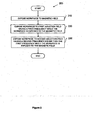
- Figure 2 illustrates an exemplary method for altering characteristics of a workpiece.
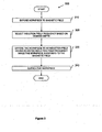
- Figure 3 illustrates an exemplary method for altering characteristics of a workpiece.
- Exemplary apparatus and processes of the present disclosure involve exposure of a workpiece to a magnetic field and to associated thermal treatment such that characteristics of a workpiece material are affected by both the magnetic field and the thermal treatment.
- the thermal treatment involves an induction heating process at relatively high frequencies such that the workpiece material is affected through less than the entire body of the workpiece or substantially only at the workpiece's outer surface. Characteristics of the workpiece material may be altered in part based on the degree to which the material conducts electricity.
- Figure 1 illustrates an exemplary apparatus 100 for altering characteristics of a workpiece W.
- the workpiece W may be raw stock material or it may be finished or semifinished material such as a forging whose physical, mechanical, magnetic, and other characteristics may be improved by use of the apparatus 100.
- the apparatus 100 includes a magnetic field generator 110 that generates a magnetic field within which the workpiece W can be positioned.
- the magnetic field generator 110 includes a coil, a cross sectional view of which is shown, constructed from a superconducting material.
- the magnetic field generator 110 includes a coil constructed from material other than superconducting material.
- the magnetic field generator may not include a coil, but may include a core or may be a resistive magnet, a permanent magnet, a hybrid magnet, and so on.
- the magnetic field generator 110 generates a magnetic field with a magnetic flux density of between 1 and 30 Tesla.
- the magnetic field generator 110 generates a magnetic field with a magnetic flux density of approximately 9 Tesla. In other embodiments, the magnetic field generator 110 may generate magnetic fields in excess of 30 Tesla.
- the apparatus 100 further includes an induction heating coil 120 for purposes of heat treating the workpiece W.
- the induction heating coil 120 is configured for induction heating of the workpiece W while the workpiece W is exposed to the magnetic field generated by the magnetic field generator 110.
- Alternating current provided at the leads 125a-b flows through the induction heating coil 120 and generates a changing magnetic field, also known as an induction field, within which the workpiece W can be positioned.
- the induction field induces electromotive forces (EMF) in the workpiece W that, in turn, produce eddy currents within the workpiece W. Since the workpiece W has an internal resistance to current flow, the eddy currents generate heat that causes a rise in temperature within the workpiece W.
- EMF electromotive forces
- Induction fields that have a relatively higher frequency induce heating currents in the workpiece W to flow more near the outer surface of the workpiece W and less near the core or center of the workpiece W.
- heating of the workpiece W may be concentrated at or near its outer surface. This selective heating may be beneficial if a desired result is to alter the characteristics of the workpiece W at or near its outer surface.
- the induction coil 120 is configured to generate an induction field having a frequency such that the induction field causes heating current to flow through only a selected portion of the workpiece that is less than the entire workpiece W.
- the required frequencies for induction heating the entire body of the workpiece W or less than the entire body of the workpiece W would depend on the workpiece W itself (e.g. material, geometry, and so on).
- the apparatus 100 further includes a case depth selection logic 130 which is operably connected to the coil 120 via the leads 125a-b.
- the case depth selection logic 130 controls or allows a user to control certain parameters of the induction field based on a desired case depth of the portion of the workpiece to be treated.
- the case depth selection logic 130 selects the case depth in the sense that it controls various parameters (e.g. frequency, alternating current, exposure times, and so on) of induction fields generated by the induction coil 120.
- the coil 120 is configured to generate induction fields based on the parameters indicated by the case depth selection logic 130.
- the characteristics of alternating current corresponding to the induction field are such that the selected portion is substantially only the outer surface of the workpiece W.
- the required frequency for induction heating only the outer surface of the workpiece W would depend on the workpiece W itself (e.g. material, geometry, and so on). However, the frequency required for induction heating only the outer surface of the workpiece W is a substantially higher frequency than the frequency required for induction heating the entire body of the workpiece W.
- substantially only the outer surface of the workpiece W corresponds to an effective case depth of between about 0.020 inches and about 0.040 inches. In other embodiments, substantially only the outer surface of the workpiece W may correspond to an effective case depth larger than about 0.020 inches or less than about 0.040 inches.
- the induction coil 120 is configured to generate an induction field with a frequency of approximately 10 kHz. In other embodiments, the induction coil 120 is configured to generate an induction field with a frequency in the range of from 3 kHz to 20 kHz. In other embodiments, the induction coil 120 is configured to generate an induction field with a frequency in ranges other than from 3 kHz to 20 kHz.
- the induction coil 120 is configured to generate an induction field having a frequency such that heating of the workpiece W occurs substantially through the entire body of the workpiece W.
- the induction heating coil 120 generates two induction fields, one after the other.
- the first induction field first heats substantially the entire workpiece W to a first temperature in the presence of the magnetic field, after which the second induction field heats substantially only the outer surface of the workpiece W to a second temperature in the presence of the magnetic field.
- the induction heating coil 120 may generate only one induction field or it may generate more than two induction fields.
- the first temperature corresponds to substantially the workpiece W material's Curie temperature and the second temperature corresponds to a temperature above which the material is in the austenite phase.
- the induction heating coil 120 heats substantially the entire body of the workpiece W to substantially the material's Curie temperature (e.g. approximately 768°C (1414°F) for steel or approximately 200°C to 300°C (400°F to 600°F) for cast iron, and so on) while the workpiece W is exposed to the magnetic field generated by the magnetic field generator 110.
- the induction heating coil 120 heats substantially the outer surface and near outer surface of the workpiece W to a temperature that causes the material to be completely in the austenitic phase (e.g.
- This second induction heating step is followed by rapid cooling or quenching.
- the outer surface becomes hard, while the core remains ductile and tough.
- the modified microstructure of the workpiece W material provides improved wear resistance and creep resistance.
- the required exposure times for exposure of the workpiece W to the magnetic fields or induction fields would depend on the workpiece W itself (e.g. material, geometry, and so on) and the desired characteristics for the workpiece W after exposure.
- the apparatus 100 may be used to heat portions of the workpiece W other than the entire workpiece W or the outer surface of the workpiece W to temperatures other than those discussed above (e.g. heating the surface and near surface of the workpiece W above the material's eutectoid temperature, tempering, and so on) to obtain desired characteristics in the workpiece W material.
- heating of substantially the entire body of the workpiece W to the first temperature may be accomplished by alternative heating methods (not shown) other than induction heating.
- Exemplary alternative heating methods include convection heating, resistance heating, electric arc heating, conduction, radiation, and so on.
- the workpiece W may be induction heated using the induction heating coil 120 to raise the temperature of the outer surface to the second temperature. Heating of substantially the entire body of the workpiece W to the first temperature by alternative heating methods other than induction heating may take place while the workpiece W is exposed to the magnetic field.
- heating of substantially the entire body of the workpiece W to the first temperature may be accomplished by a second induction heating coil (not shown).
- the second induction heating coil may be used to raise the temperature of substantially the entire body of the workpiece W to the first temperature.
- the workpiece W may be heated using the induction heating coil 120 to raise the temperature near the surface to the second temperature. Heating of substantially the entire body of the workpiece W to the first temperature using the second induction heating coil may take place while the workpiece W is exposed to the magnetic field.
- the apparatus 100 further includes a chamber 140 within which the workpiece W is positioned.
- the chamber 140 may be constructed of non-magnetic materials (e.g. ceramic, quartz, plastic, and so on), which would not be affected by the magnetic fields generated by the magnetic field generator 110 or the induction fields generated by the induction heating coil 120.
- the chamber 140 may be made of a magnetic material.
- the chamber 140 is capable of holding a vacuum. Treating the workpiece W in a vacuum may be desirable in some applications to reduce the chances that the workpiece W will oxidize during treatment.
- the apparatus 100 further includes a quencher 150.
- Quencher 150 is used to rapidly cool the workpiece W after the workpiece W has been heated.
- the quencher 150 directs cooling fluid (e.g. purge gas, quench gas, argon, helium, hydrogen, water, and so on) into the chamber 140 where it comes into contact with the workpiece W.
- the cooling fluid rapidly removes heat from the workpiece W.
- the apparatus 100 may not include the quencher 150 and quenching of the workpiece W may be accomplished by means external to the apparatus 100.
- the workpiece W is tempered by heating the workpiece W to a temperature between the ranges of 150°C to 260°C and 370°C to 650°C while the workpiece W is exposed to the magnetic field generated by the magnetic field generator 110.
- the workpiece W may be tempered by induction heating the workpiece W using the induction heating coil 120.
- the workpiece W may be heated to approximately 180°C for approximately 10 to 20 minutes while the workpiece W is positioned within the magnetic field generated by the magnetic field generator 110.
- the workpiece W may be tempered within the magnetic field at temperatures outside the ranges of 150°C to 260°C and 370°C to 650°C and for periods of times other than 10 to 20 minutes.
- the apparatus 100 may further include controls (not shown) in addition to case depth selection logic 130.
- the controls can be manual or programmable to initiate and control operation of the various treatments of the workpiece W described above.
- Operations and settings that may be controlled, in addition to frequency and current include, but are not limited to, operation of the magnetic generator, operation of the heating equipment, temperature, appropriate hold times at each temperature, delivery of quenching fluids, safety shutdowns, and so on.
- Example methods may be better appreciated with reference to the flow diagrams of Figures 2 and 3 . While for purposes of simplicity of explanation, the illustrated methodologies are shown and described as a series of blocks, it is to be appreciated that the methodologies are not limited by the order of the blocks, as some blocks can occur in different orders or concurrently with other blocks from that shown or described. Moreover, less than all the illustrated blocks may be required to implement an example methodology. Furthermore, additional or alternative methodologies can employ additional, not illustrated blocks. While Figures 2 and 3 illustrate various actions occurring in serial, it is to be appreciated that various actions illustrated in Figures 2 and 3 could occur substantially in parallel.
- Figure 2 illustrates an exemplary method 200 of altering characteristics of a workpiece.
- the method 200 exposes a workpiece to a magnetic field.
- the method 200 exposes the workpiece to a first induction field having a first frequency.
- the method 200 exposes the workpiece to a second induction field having a second frequency substantially higher than the first frequency.
- the second frequency may be configured such that second induction field heats a portion of the workpiece that is less than the entire workpiece while the workpiece is exposed to the magnetic field.
- the second induction field is configured to heat substantially only the outer surface of the workpiece while the workpiece is exposed to the magnetic field. In one embodiment, the second induction field is configured to heat substantially only the outer surface to a temperature above which the material is in the austenite phase while the workpiece is exposed to the magnetic field.
- the method 200 includes the first induction field heating substantially the entire body of the workpiece to the material's Curie temperature while the workpiece is exposed to the magnetic field prior to exposing the workpiece to the second induction field.
- the method 200 includes quenching the workpiece. In one embodiment, the quenching the workpiece occurs while the workpiece is exposed to the magnetic field.
- the method 200 includes tempering the workpiece while the workpiece is exposed to the magnetic field.
- the tempering temperature is approximately 180° C and the workpiece is tempered for about 10 minutes.
- the workpiece may be tempered at temperatures other than 180° C and for periods of time different than about 10 minutes while the workpiece is exposed to the magnetic field
- Figure 3 illustrates an exemplary method 300 of selectively heating a portion of a workpiece to alter characteristics of the workpiece.
- the method 300 includes exposing the workpiece to a magnetic field.
- the method 300 includes selecting an induction field frequency based on a desired depth of the portion to be heated.
- the method 300 includes exposing the workpiece to an induction field having a frequency corresponding to the selected induction field frequency while the workpiece is exposed to the magnetic field to heat the portion to the desired depth.
- the method 300 further includes quenching the workpiece.
- characteristics of the workpiece material may be improved.
- portions of the workpiece may be selectively affected.
- the frequency of the induction field may be selected to specify a case depth of the workpiece to be heated by the induction field while simultaneous being exposed to the magnetic field.
- Various different case depths of the workpiece may be affected with different combinations of parameters to improve different characteristics. In some cases, the case depth may correspond to substantially only the outer surface of the workpiece. Characteristics such as hardness, ductility, toughness, wear resistance, and creep resistance, among others, of selected portions of the workpiece may be selectively improved.
- Logic includes but is not limited to hardware, firmware, software or combinations of each to perform a function(s) or an action(s), or to cause a function or action from another logic, method, or system.
- logic may include manually adjustable circuitry, a software controlled microprocessor, discrete logic like an application specific integrated circuit (ASIC), a programmed logic device, a memory device containing instructions, or the like.
- ASIC application specific integrated circuit
- Logic may include one or more gates, combinations of gates, or other circuit components. Logic may also be fully embodied as software.
- operably connected is one by which the operably connected components or the operable connection perform its intended purpose.
- two components may be operably connected to each other directly or through one or more intermediate components.
- two components can be operably connected by being able to communicate signals to each other directly or through one or more intermediate components such as a conductor, a wire, a processor, a logic, or other component.
Landscapes
- Chemical & Material Sciences (AREA)
- Engineering & Computer Science (AREA)
- Physics & Mathematics (AREA)
- Thermal Sciences (AREA)
- Crystallography & Structural Chemistry (AREA)
- Mechanical Engineering (AREA)
- Materials Engineering (AREA)
- Metallurgy (AREA)
- Organic Chemistry (AREA)
- Electromagnetism (AREA)
- Heat Treatment Of Articles (AREA)
Applications Claiming Priority (1)
| Application Number | Priority Date | Filing Date | Title |
|---|---|---|---|
| US12/904,698 US20120091122A1 (en) | 2010-10-14 | 2010-10-14 | Selective case depth thermo-magnetic processing and apparatus |
Publications (2)
| Publication Number | Publication Date |
|---|---|
| EP2441849A2 true EP2441849A2 (fr) | 2012-04-18 |
| EP2441849A3 EP2441849A3 (fr) | 2012-08-08 |
Family
ID=45098769
Family Applications (1)
| Application Number | Title | Priority Date | Filing Date |
|---|---|---|---|
| EP11008310A Withdrawn EP2441849A3 (fr) | 2010-10-14 | 2011-10-14 | Traitement et appareil thermomagnétique sélectif de profondeur de pénétration de trempe |
Country Status (2)
| Country | Link |
|---|---|
| US (1) | US20120091122A1 (fr) |
| EP (1) | EP2441849A3 (fr) |
Cited By (5)
| Publication number | Priority date | Publication date | Assignee | Title |
|---|---|---|---|---|
| WO2014088423A1 (fr) * | 2012-12-04 | 2014-06-12 | Sinvent As | Appareil et procédé pour chauffage par induction de matériaux magnétiques |
| EP2779789A1 (fr) * | 2013-03-15 | 2014-09-17 | National Oilwell Varco, L.P. | Système et procédé de traitement thermique d'un tubulaire |
| IT201700031443A1 (it) * | 2017-03-22 | 2018-09-22 | Univ Bologna Alma Mater Studiorum | Apparato e metodo di riscaldamento ad induzione |
| EP3394295A4 (fr) * | 2015-12-22 | 2019-11-13 | Ecole de Technologie Supérieure | Procédé de traitement thermique par induction d'un composant d'alliage pour générer des gradients de microstructure et un composant d'alliage thermiquement traité selon le procédé |
| WO2025238668A1 (fr) | 2024-05-14 | 2025-11-20 | Alma Mater Studiorum - Università di Bologna | Appareil de chauffage par induction de métaux ferromagnétiques |
Families Citing this family (14)
| Publication number | Priority date | Publication date | Assignee | Title |
|---|---|---|---|---|
| US8784425B2 (en) | 2007-02-28 | 2014-07-22 | Smith & Nephew, Inc. | Systems and methods for identifying landmarks on orthopedic implants |
| EP2114264B1 (fr) | 2007-02-28 | 2019-07-03 | Smith & Nephew, Inc. | Implant orthopédique instrumenté pour identifier un repère |
| EP3545878A3 (fr) * | 2007-02-28 | 2019-12-25 | Smith & Nephew, Inc | Système permettant d'identifier un point de repère |
| US9220514B2 (en) | 2008-02-28 | 2015-12-29 | Smith & Nephew, Inc. | System and method for identifying a landmark |
| US9031637B2 (en) * | 2009-04-27 | 2015-05-12 | Smith & Nephew, Inc. | Targeting an orthopaedic implant landmark |
| US8945147B2 (en) | 2009-04-27 | 2015-02-03 | Smith & Nephew, Inc. | System and method for identifying a landmark |
| US8086734B2 (en) | 2009-08-26 | 2011-12-27 | International Business Machines Corporation | Method of autonomic representative selection in local area networks |
| RU2012157125A (ru) | 2010-06-03 | 2014-07-20 | Смит Энд Нефью, Инк. | Ортопедический имплантат |
| US8890511B2 (en) | 2011-01-25 | 2014-11-18 | Smith & Nephew, Inc. | Targeting operation sites |
| US9526441B2 (en) * | 2011-05-06 | 2016-12-27 | Smith & Nephew, Inc. | Targeting landmarks of orthopaedic devices |
| CA2839060A1 (fr) | 2011-06-16 | 2012-12-20 | Smith & Nephew, Inc. | Alignement chirurgical a l'aide de references |
| USD727510S1 (en) * | 2012-08-30 | 2015-04-21 | Sechrist Industries, Inc. | Hyperbaric chamber gurney storage device |
| US9133530B2 (en) | 2013-03-14 | 2015-09-15 | Ajax Tocco Magnethermic Corp. | High magnetic hardening assembly and method |
| CN114262769A (zh) * | 2014-09-22 | 2022-04-01 | 麦格纳国际公司 | 包括产生局部软区的热磁回火工艺的用于制造结构部件的方法 |
Family Cites Families (6)
| Publication number | Priority date | Publication date | Assignee | Title |
|---|---|---|---|---|
| US20040084443A1 (en) * | 2002-11-01 | 2004-05-06 | Ulrich Mark A. | Method and apparatus for induction heating of a wound core |
| US20050039830A1 (en) * | 2003-08-19 | 2005-02-24 | Mark Christofis | Induction heat treatment method and coil and article treated thereby |
| US7161124B2 (en) * | 2005-04-19 | 2007-01-09 | Ut-Battelle, Llc | Thermal and high magnetic field treatment of materials and associated apparatus |
| US7534980B2 (en) * | 2006-03-30 | 2009-05-19 | Ut-Battelle, Llc | High magnetic field ohmically decoupled non-contact technology |
| EP2746411A3 (fr) * | 2007-11-12 | 2014-10-15 | Topy Kogyo Kabushiki Kaisha | Procédé de traitement thermique de travail en forme de colonne |
| JP2011526653A (ja) * | 2008-06-30 | 2011-10-13 | イートン コーポレーション | 金属及び合金を磁気処理して、次世代材料を調整するための連続生産システム |
-
2010
- 2010-10-14 US US12/904,698 patent/US20120091122A1/en not_active Abandoned
-
2011
- 2011-10-14 EP EP11008310A patent/EP2441849A3/fr not_active Withdrawn
Non-Patent Citations (1)
| Title |
|---|
| None |
Cited By (9)
| Publication number | Priority date | Publication date | Assignee | Title |
|---|---|---|---|---|
| WO2014088423A1 (fr) * | 2012-12-04 | 2014-06-12 | Sinvent As | Appareil et procédé pour chauffage par induction de matériaux magnétiques |
| EP2779789A1 (fr) * | 2013-03-15 | 2014-09-17 | National Oilwell Varco, L.P. | Système et procédé de traitement thermique d'un tubulaire |
| US10034330B2 (en) | 2013-03-15 | 2018-07-24 | National Oilwell Varco, L.P. | System and method for heat treating a tubular |
| US10841985B2 (en) | 2013-03-15 | 2020-11-17 | National Oilwell Varco, L.P. | System and method for heat treating a tubular |
| EP3394295A4 (fr) * | 2015-12-22 | 2019-11-13 | Ecole de Technologie Supérieure | Procédé de traitement thermique par induction d'un composant d'alliage pour générer des gradients de microstructure et un composant d'alliage thermiquement traité selon le procédé |
| US11136634B2 (en) | 2015-12-22 | 2021-10-05 | École De Technologie Supérieure | Method for heat treating by induction an alloy component for generating microstructure gradients and an alloy component heat treated according to the method |
| IT201700031443A1 (it) * | 2017-03-22 | 2018-09-22 | Univ Bologna Alma Mater Studiorum | Apparato e metodo di riscaldamento ad induzione |
| WO2018172929A1 (fr) * | 2017-03-22 | 2018-09-27 | Alma Mater Studiorum - Universita' Di Bologna | Appareil et procédé de chauffage par induction |
| WO2025238668A1 (fr) | 2024-05-14 | 2025-11-20 | Alma Mater Studiorum - Università di Bologna | Appareil de chauffage par induction de métaux ferromagnétiques |
Also Published As
| Publication number | Publication date |
|---|---|
| US20120091122A1 (en) | 2012-04-19 |
| EP2441849A3 (fr) | 2012-08-08 |
Similar Documents
| Publication | Publication Date | Title |
|---|---|---|
| US20120091122A1 (en) | Selective case depth thermo-magnetic processing and apparatus | |
| CN1973578B (zh) | 通过感应加热对工件进行多频加热处理 | |
| EP2236005B1 (fr) | Chauffage par induction électrique contrôlé d'une pièce à travailler dans une bobine solénoïde avec compensateurs de flux | |
| Rudnev | An objective assessment of magnetic flux concentrators | |
| CN105324496B (zh) | 用于复杂工件的单发感应加热的感应器 | |
| US20150071702A1 (en) | Structural body and production method for the same | |
| JP5489325B2 (ja) | 高周波誘導加熱方法及び高周波誘導加熱装置 | |
| Sabeeh et al. | A 3D FEA approach to design an induction coil for case hardening of a carbon steel gear | |
| EP3168313B1 (fr) | Cémentation d'induction à basse pression | |
| US20100263770A1 (en) | Flash tempering process and apparatus | |
| Rudnev et al. | Tempering of induction hardened steels | |
| Balachandran et al. | Studies on induction hardening of gray iron and ductile iron | |
| JPH05112809A (ja) | 超強靱鋼の製造方法 | |
| JPH0236646B2 (ja) | Shintanyakiirebuhinnobubunyakimodoshihoho | |
| WO2023211718A1 (fr) | Application de traitement thermique par induction magnétiquement améliorée | |
| EP4411004A1 (fr) | Traitement thermique sélectif de métaux à l'aide d'un système de four à serpentin | |
| Ahmad et al. | Relationthip Between Case Depth and Hardness in an Induction Hardened Medium Carbon Steel | |
| US20240254578A1 (en) | Selective heat treatment of metals using multiple induction heating coils | |
| Eimuss et al. | Does 3D-Printed Coil Perform Better for Induction Hardening and How to Predict the Performance Based on Numerical Simulation? | |
| Klug et al. | Characterization of the Sintered Steel Astaloy CrA for the Simulation of Induction Surface Hardening of Small-Modulus Gear Wheels | |
| JP5153484B2 (ja) | 加熱部位選択的誘導加熱方法 | |
| CN101326294A (zh) | 快速回火工艺与设备 | |
| JP5438817B2 (ja) | 加熱部位選択的誘導加熱装置 | |
| JPS61127812A (ja) | 鋼の熱処理方法 | |
| JP2017197800A (ja) | 鉄系合金及びその製造方法 |
Legal Events
| Date | Code | Title | Description |
|---|---|---|---|
| PUAI | Public reference made under article 153(3) epc to a published international application that has entered the european phase |
Free format text: ORIGINAL CODE: 0009012 |
|
| AK | Designated contracting states |
Kind code of ref document: A2 Designated state(s): AL AT BE BG CH CY CZ DE DK EE ES FI FR GB GR HR HU IE IS IT LI LT LU LV MC MK MT NL NO PL PT RO RS SE SI SK SM TR |
|
| AX | Request for extension of the european patent |
Extension state: BA ME |
|
| PUAL | Search report despatched |
Free format text: ORIGINAL CODE: 0009013 |
|
| AK | Designated contracting states |
Kind code of ref document: A3 Designated state(s): AL AT BE BG CH CY CZ DE DK EE ES FI FR GB GR HR HU IE IS IT LI LT LU LV MC MK MT NL NO PL PT RO RS SE SI SK SM TR |
|
| AX | Request for extension of the european patent |
Extension state: BA ME |
|
| RIC1 | Information provided on ipc code assigned before grant |
Ipc: H05B 6/10 20060101ALI20120629BHEP Ipc: C21D 1/18 20060101ALI20120629BHEP Ipc: C21D 9/00 20060101ALI20120629BHEP Ipc: C21D 1/42 20060101ALI20120629BHEP Ipc: C21D 1/10 20060101AFI20120629BHEP |
|
| 17P | Request for examination filed |
Effective date: 20130208 |
|
| STAA | Information on the status of an ep patent application or granted ep patent |
Free format text: STATUS: THE APPLICATION IS DEEMED TO BE WITHDRAWN |
|
| 18D | Application deemed to be withdrawn |
Effective date: 20150501 |