EP2441888A2 - Engin automobile - Google Patents
Engin automobile Download PDFInfo
- Publication number
- EP2441888A2 EP2441888A2 EP11008191A EP11008191A EP2441888A2 EP 2441888 A2 EP2441888 A2 EP 2441888A2 EP 11008191 A EP11008191 A EP 11008191A EP 11008191 A EP11008191 A EP 11008191A EP 2441888 A2 EP2441888 A2 EP 2441888A2
- Authority
- EP
- European Patent Office
- Prior art keywords
- construction machine
- steering
- drives
- trajectory
- unit
- Prior art date
- Legal status (The legal status is an assumption and is not a legal conclusion. Google has not performed a legal analysis and makes no representation as to the accuracy of the status listed.)
- Granted
Links
Images


Classifications
-
- E—FIXED CONSTRUCTIONS
- E01—CONSTRUCTION OF ROADS, RAILWAYS, OR BRIDGES
- E01C—CONSTRUCTION OF, OR SURFACES FOR, ROADS, SPORTS GROUNDS, OR THE LIKE; MACHINES OR AUXILIARY TOOLS FOR CONSTRUCTION OR REPAIR
- E01C23/00—Auxiliary devices or arrangements for constructing, repairing, reconditioning, or taking-up road or like surfaces
- E01C23/06—Devices or arrangements for working the finished surface; Devices for repairing or reconditioning the surface of damaged paving; Recycling in place or on the road
- E01C23/08—Devices or arrangements for working the finished surface; Devices for repairing or reconditioning the surface of damaged paving; Recycling in place or on the road for roughening or patterning; for removing the surface down to a predetermined depth high spots or material bonded to the surface, e.g. markings; for maintaining earth roads, clay courts or like surfaces by means of surface working tools, e.g. scarifiers, levelling blades
- E01C23/085—Devices or arrangements for working the finished surface; Devices for repairing or reconditioning the surface of damaged paving; Recycling in place or on the road for roughening or patterning; for removing the surface down to a predetermined depth high spots or material bonded to the surface, e.g. markings; for maintaining earth roads, clay courts or like surfaces by means of surface working tools, e.g. scarifiers, levelling blades using power-driven tools, e.g. vibratory tools
- E01C23/088—Rotary tools, e.g. milling drums
-
- B—PERFORMING OPERATIONS; TRANSPORTING
- B62—LAND VEHICLES FOR TRAVELLING OTHERWISE THAN ON RAILS
- B62D—MOTOR VEHICLES; TRAILERS
- B62D15/00—Steering not otherwise provided for
- B62D15/02—Steering position indicators ; Steering position determination; Steering aids
- B62D15/027—Parking aids, e.g. instruction means
- B62D15/0275—Parking aids, e.g. instruction means by overlaying a vehicle path based on present steering angle over an image without processing that image
-
- B—PERFORMING OPERATIONS; TRANSPORTING
- B62—LAND VEHICLES FOR TRAVELLING OTHERWISE THAN ON RAILS
- B62D—MOTOR VEHICLES; TRAILERS
- B62D7/00—Steering linkage; Stub axles or their mountings
- B62D7/06—Steering linkage; Stub axles or their mountings for individually-pivoted wheels, e.g. on king-pins
- B62D7/14—Steering linkage; Stub axles or their mountings for individually-pivoted wheels, e.g. on king-pins the pivotal axes being situated in more than one plane transverse to the longitudinal centre line of the vehicle, e.g. all-wheel steering
- B62D7/15—Steering linkage; Stub axles or their mountings for individually-pivoted wheels, e.g. on king-pins the pivotal axes being situated in more than one plane transverse to the longitudinal centre line of the vehicle, e.g. all-wheel steering characterised by means varying the ratio between the steering angles of the steered wheels
- B62D7/1509—Steering linkage; Stub axles or their mountings for individually-pivoted wheels, e.g. on king-pins the pivotal axes being situated in more than one plane transverse to the longitudinal centre line of the vehicle, e.g. all-wheel steering characterised by means varying the ratio between the steering angles of the steered wheels with different steering modes, e.g. crab-steering, or steering specially adapted for reversing of the vehicle
-
- E—FIXED CONSTRUCTIONS
- E01—CONSTRUCTION OF ROADS, RAILWAYS, OR BRIDGES
- E01C—CONSTRUCTION OF, OR SURFACES FOR, ROADS, SPORTS GROUNDS, OR THE LIKE; MACHINES OR AUXILIARY TOOLS FOR CONSTRUCTION OR REPAIR
- E01C19/00—Machines, tools or auxiliary devices for preparing or distributing paving materials, for working the placed materials, or for forming, consolidating, or finishing the paving
- E01C19/004—Devices for guiding or controlling the machines along a predetermined path
-
- E—FIXED CONSTRUCTIONS
- E02—HYDRAULIC ENGINEERING; FOUNDATIONS; SOIL SHIFTING
- E02F—DREDGING; SOIL-SHIFTING
- E02F9/00—Component parts of dredgers or soil-shifting machines, not restricted to one of the kinds covered by groups E02F3/00 - E02F7/00
- E02F9/20—Drives; Control devices
- E02F9/2058—Electric or electro-mechanical or mechanical control devices of vehicle sub-units
- E02F9/2087—Control of vehicle steering
-
- E—FIXED CONSTRUCTIONS
- E02—HYDRAULIC ENGINEERING; FOUNDATIONS; SOIL SHIFTING
- E02F—DREDGING; SOIL-SHIFTING
- E02F9/00—Component parts of dredgers or soil-shifting machines, not restricted to one of the kinds covered by groups E02F3/00 - E02F7/00
- E02F9/26—Indicating devices
Definitions
- the invention relates to a self-propelled construction machine, which has a chassis with front and rear wheels or drives in the working direction, which is supported by the chassis.
- the known self-propelled construction machines which include in particular the road milling machines, recyclers or stabilizers, have a working device for carrying out the construction measure.
- the working device may for example be a milling device, in particular a milling drum.
- Such construction machines differ from motor vehicles, in particular passenger cars, in that the construction machine can be steered both with the front wheels or drives and with the rear wheels or drives.
- the machine operator should be instructed by a second person when resetting. Nevertheless, the reset is difficult because the operator even the rear area can see only limited.
- construction machines which have a camera on the back and a screen on the control station. Although the machine operator of the construction machine can then see the rear area, but it can also be difficult to estimate with a camera, as the construction machine moves when resetting.
- driver assistance systems For motor vehicles, especially cars, devices are known that assisted the driver when parking the vehicle. Such devices are also referred to as driver assistance systems.
- the DE 103 34 613 A1 describes a device for motor vehicles, which indicates the range of motion of the vehicle on a screen, which is also referred to as a driving tube, depending on the chosen steering angle.
- a driver assistance system for towing vehicles with trailer is from the WO 2008/012109 A1 known.
- driver assistance systems for cars and trucks are not suitable for self-propelled construction machines that can be steered with both the front wheels or drives and with the rear wheels or drives. Also, the height adjustment with a longitudinal and transverse inclination of the machine frame makes special demands on a driver assistance system for self-propelled construction machines.
- the invention has for its object to provide a self-propelled construction machine that facilitates the machine operator reversing, especially for loading, attaching or parking the construction machine.
- the self-propelled construction machine is characterized by a device for assisting the operator when reversing, comprising a unit for detecting the position of the front wheels or drives and rear wheels or drives and a computing unit for determining data, the at least one trajectory of the construction machine in Depend on the position of the front wheels or drives and the rear wheels or drives.
- the device for assisting the machine operator has an image recording unit for recording an image of the rear area of the construction machine and a display unit for displaying the recorded image of the rear area of the construction machine.
- An image processing unit superimposes on the image of the rear area of the construction machine displayed on the display unit the representation of at least one trajectory with which the movement of the construction machine in the field or on traffic routes or areas is described.
- the device for assisting the operator when reversing considers both the position of the front and rear wheels or drives.
- One or more trajectories may be determined superimposed on the image of the rear of the construction machine.
- the operator can accurately estimate when reversing how the construction machine moves depending on the position of both the front and rear wheels or drives to possibly existing obstacles.
- the operating unit of the construction machine has both means for prescribing a steering angle for the front and / or rear wheels or drives as well as means for selecting a steering mode from a plurality of steering modes.
- the operating unit of the construction machine interacts with the steering device of the machine such that the steering device sets the predetermined steering angle or the selected steering mode.
- the arithmetic unit of the device for assisting the machine operator in reversing which determines the data describing at least one trajectory of the construction machine in dependence on the position of the front and rear wheels or drives, has in the preferred embodiment means for calculating at least the a Trajectory descriptive data not only in dependence on the position of the front and / or rear wheels or drives, but also in dependence on the selected steering mode.
- the operator can immediately recognize how the engine behaves when reversing.
- the operator can estimate what effects have different steering angles or steering modes. This makes it possible for the operator to not only better estimate the movement of the machine when reversing, but also to specify the optimum steering angle in optimum steering mode or vice versa.
- the means for calculating the data describing the at least one trajectory are formed in a particularly preferred embodiment such that the data describe the trajectory in the selected steering mode and the predetermined steering angle in a coordinate system related to the chassis of the construction machine.
- This coordinate system is preferably a coordinate system that does not change when the machine frame is adjusted in height with respect to the chassis with a predetermined lateral and / or longitudinal inclination.
- a preferred embodiment of the construction machine according to the invention assumes that the steering of the construction machine essentially satisfies the Ackermann law, so that the extension of the axes of the wheels or drives intersect at a curve center.
- the trajectories can be represented by circular arcs, which can be described by start and end point as well as a curve center and / or radius.
- the at least one trajectory is a straight line, which is the case with a steering in the same direction, the trajectory can be described solely by the start and end points.
- the arithmetic unit preferably has means for converting the data describing the at least one trajectory into a coordinate system related to the image recording unit, in which the image is displayed on the display unit. This makes it possible to select a different coordinate system for the image recording unit than the coordinate system of the construction machine. Consequently, the image recording unit can be arbitrarily arranged on the construction machine so as to be able to show the operator an image from a certain viewpoint.
- the machine frame is adjustable in height and / or inclination. It is advantageous if the correct representation of the at least one trajectory in the image of the rear area displayed on the display unit takes place independently of the height and / or inclination of the machine frame. Therefore, in another particularly preferred embodiment, the arithmetic unit comprises means for correcting the data describing the at least one trajectory in the coordinate system related to the image recording unit based on a correction function including a change in the pitch and / or bank angle and / or height of the image recording unit is taken into account with respect to the coordinate system related to the chassis of the construction machine.
- a change in the height and / or inclination of the machine frame relative to the coordinate system relative to the chassis of the construction machine also leads to a change in the height and / or inclination of the image recording unit arranged on the machine frame.
- the means for correcting the data describing the at least one trajectory ensure that a change in the height and / or inclination of the machine frame relative to the coordinate system related to the chassis of the construction machine does not lead to a false display of the at least one trajectory on the display unit.
- the data describing the at least one trajectory are thus transformed depending on the height and / or inclination of the machine frame so that they again match the image of the rear area that is displayed on the display unit.
- a particularly preferred embodiment provides means for correcting the data describing the at least one trajectory in the coordinate system related to the image recording unit on the basis of a correction function taking into account distortion of the image recorded by the image recording unit.
- the at least one trajectory is distorted as the image of the rear region is distorted.
- This particularly preferred embodiment has a relatively low computational power because it does not need to equalize the image, but only distorts the trajectory to show both representations on the display unit in correct relationship.
- the arithmetic unit has means for correcting the image of the rear area of the construction machine in the coordinate system related to the image recording unit on the basis of a correction function with which distortion of the image recorded by the image recording unit is corrected. For this purpose, however, a higher computing power is required.
- a trajectory is a trajectory that describes any point. This point can be on the construction machine to mark exactly one point of the machine, or even next to the machine to mark a safe distance from a point on the machine.
- the data describing the at least one trajectory may be different data.
- the trajectory can be described by a start and end point as well as a circle center or a radius.
- the distance between start and end point may be the vehicle length or part of the vehicle length.
- a plurality of trajectories are displayed, wherein one of the trajectories represents the vehicle length and the other trajectories represent parts of the vehicle length.
- the point should be at the extreme end of the rear of the machine to accommodate the When reversing, the operator should indicate the position of the stern.
- a trajectory for example, the movement of a point on the working device of the machine, for example the milling device, can be visualized.
- the trajectories can be displayed not only as lines between start and end points, but also as point clouds to visualize the movement of the construction machine on the display unit.
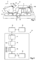
- Fig. 1 shows a road milling machine as an example of a self-propelled construction machine, which has a device to assist the operator when reversing.
- the road milling machine is a so-called large milling machine for milling road surfaces.
- the construction machine has a chassis 1 which has two front drives 2, 3 and two rear drives 4, 5 in the working direction I.
- the chassis can also have front and rear wheels.
- the drives are simply referred to as wheels.
- the chassis 1 carries a machine frame 6, which is adjustable by means of two front and two rear lifting columns 7, 8 in relation to the terrain or the traffic route or the traffic area in height, with the longitudinal and / or transverse inclination of the machine frame 6 is adjustable ,
- the construction machine has an unillustrated measuring device with which the position of the machine frame with respect to a reference plane, ie the height and inclination of the machine frame with respect to the reference plane, is detected.
- a measuring device is in the WO 2007/031531 A1 described.
- the construction machine has a non-illustrated drive means 9 for driving the front and rear wheels 2, 3; 4, 5 and a steering device 10 for steering the front and rear wheels 2, 3; 4, 5 and a milling device 19 with a milling drum 20 which is arranged between the front and rear wheels.
- control station 11 On the machine frame 6 is between front and rear wheels 2, 3; 4, 5 arranged the control station 11 of the construction machine.
- the driver's station can of course also be arranged at a different location, such. B. in front of the front wheels.
- the operating unit 12 has means 12A for prescribing a specific steering angle for the front and rear wheels 2, 3 and means 12B for selecting a specific steering mode.
- the means 12A for setting the steering angle may be a steering wheel 12A, while the means for selecting the steering mode may be a selector lever 12B. Steering wheel 12A and selector lever 12B are in Fig. 1 hinted at.
- the operating unit 12 cooperates with the steering device 10 as follows.
- the operator may select a particular steering mode from a plurality of steering modes with the select lever 12B.
- a steering mode called “coordinated steering” the construction machine with front and rear wheels 2, 3; 4, 5 directed in opposite directions, the front wheels 2 and 3 show the rear wheels in opposite directions.
- the operator chooses this steering mode if he wants to drive a tight radius.
- a steering mode called “crab steering” the construction machine is steered in the same direction as the front and rear wheels 2, 3, 4, 5, with the front wheels 2, 3 and the rear wheels 4, 5 pointing in the same direction If the construction machine is to travel laterally, the construction machine can also be steered only with the front wheels or only with the rear wheels.
- the operator only steers the construction machine with the steering wheel 12A.
- the rear wheels only the front wheels or both the front and rear wheels steered, in which case the front and rear wheels are steered either in the same direction or in opposite directions.
- the self-adjusting steering angle at the front and rear axles are predetermined by the geometry of the steering device, which will be explained below.
- Fig. 2 shows the block diagram of the device 13 for assisting the machine operator during reversing, which cooperates with the steering device 10 and the control unit 12 of the construction machine.
- the device 13 for assistance in reversing has a display unit 14, for example, arranged on the control station 12 screen (display) on which a picture of the rear Area of the construction machine is displayed together with one or more trajectories, with which the operator can estimate how the construction machine moves at a predetermined steering angle and the selected steering mode.
- the image of the rear portion of the construction machine is recorded with an image recording unit 15 having a camera 15A disposed at the rear of the machine frame.
- the camera 15A follows the movements of the machine frame 6 of the construction machine in relation to height and inclination relative to the terrain.
- the camera 15A is at the rear of the machine.
- the reversing assistance device 13 has a computing unit 16 with which the data describing at least one trajectory of the construction machine in dependence on the position of the front and rear wheels and in dependence on the steering mode are determined.
- the position of the front and rear wheels is detected by a unit 17, which may be part of the device 13 for assistance in reversing or part of the steering device 10.
- the block diagram of Fig. 2 shows the unit 17 as part of the device 13.
- the device 13 for assisting the machine operator has an image processing unit 18 which superimposes on the image of the rear area of the construction machine displayed on the display unit 14 the at least one trajectory which is determined by the arithmetic unit 16. Consequently, the operator sees both the at least one trajectory and the rear area of the construction machine on the display unit, so that the operator can associate the movement of the construction machine with the objects located in the field or on the traffic route.
- the at least one trajectory also more information can be displayed, such. For example, the distances.
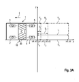
- FIGS. 3A to 3C show the simplest case where the construction machine goes straight backwards. Consequently, the steering angle ⁇ of the front and rear wheels 2, 3; 4, 5 zero.
- the chassis 1 is shown only schematically with the front and rear wheels. The representation takes place in a reference to the chassis of the construction machine coordinate system (x, y), which represents the reference plane. The position of the front and rear wheels 2, 3; 4, 5 is defined by the steering angle ⁇ .
- the machine frame 6 of the construction machine is represented in the coordinate system by a rectangle.
- the corner points of the rectangle correspond to the front and rear corner points of the machine.
- Between the front and rear wheels 2, 3; 4, 5 is the milling device 19 with the milling drum 20th
- the zero point (x0, y0) in the coordinate system related to the chassis of the machine lies on the rear left in the working direction I corner of the machine frame. 6
- the arithmetic unit 16 has means 16A which, for the representation of the backward movement of the construction machine in the present embodiment, calculate a total of six trajectories, which are each described by a starting point and an end point. Since the construction machine goes straight backwards, the trajectories are straight lines between the two points.
- the arithmetic unit calculates the coordinates (x3, y3) of the point in the vehicle Construction machine related coordinate system, where the rear left corner point of the machine frame is when the construction machine has reset by the vehicle length (l 1 ), for example 9 m. Accordingly, the arithmetic unit calculates the coordinates (x2, y2) or (x1, y1) at which the rear left vertex (x0, y0) of the construction machine is located when the construction machine by a shorter distance (l 2 or l 3 ) , For example, 3 m and 1 m, has reset.
- the trajectories T 1 to T 6 in the coordinate system related to the landing gear of the construction machine do not correspond to the display in the display unit 14 because the image recording unit 15 records the image of the rear area of the construction machine from a different angle than the angle of view Chassis of construction machine related coordinate system showing the construction machine in top view.
- the arithmetic unit 16 therefore has means 16B for converting the data, for example the coordinates (x0, y0) to (x3, y3) in the coordinate system of the construction machine (x, y) into a coordinate system (x ', y) related to the image recording unit 15 ').
- Fig. 3B shows the trajectories T 1 to T 6 in the coordinate system of the image recording unit 15, which corresponds to the coordinate system of the display unit 14.
- a change in the viewing angle of the image recording unit can thus lead to a changed representation on the display unit 14.
- the viewing angle basically does not change since the camera 12A is connected to the machine frame 6 at a predetermined viewing angle.
- the present embodiment also takes into account possible distortions that may occur when recording the image of the image recording unit.
- the lens of the camera 15A distorts, especially in the edge region. Such distortions may cause the objects in the field or on the traffic lanes or areas displayed on the display unit not to be exactly associated with the trajectories superimposed on the image of the rear area of the construction machine.
- the arithmetic unit 16 has means 16C for correcting the data (x0 ', y0') to (x3 ', y3') describing the trajectories T 1 to T 6 in the image recording unit related coordinate system (x ', y').
- the means 16C corrects the data based on a first correction function. With the first correction function, the data is corrected so that the representation of the trajectories T 1 to T 6 undergo substantially the same distortion as the image taken by the camera 15A.
- 3C shows after the correction "distorted image” of the trajectories T 1 to T 6 with the coordinates (x0 ", y0") to (x3 ", y3") in the coordinate system of the image recording unit 15, which corresponds to the coordinate system of the display unit 14.
- the "distorted image" of the trajectories T 1 to T 6 is superimposed on the image of the rear area of the construction machine recorded with the image recording unit 15.
- the machine operator can see on the display unit 14 that the construction machine moves backwards straight to the two objects, but does not touch the objects. He sees that he has to reset the construction machine by one machine length to reach the objects.
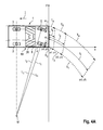
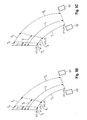
- the construction machine when reversing around a curve with reference to FIGS. 4B to 4C described, the construction machine is steered only with the rear wheels 4, 5.
- This steering mode means that the specification of certain steering angles specified by the operator acts only on the rear wheels, while the steering angle of the front wheels keeps the steering angle 0.
- the steering device 10 of the construction machine is designed such that it at least approximately backfills the Ackermann law.
- the extensions L 1 , L 2 , L 3 intersect all the wheel axles in the common center of curvature M. This assumes that the steering angle ⁇ 2 of the outside wheel is smaller than the steering angle ⁇ 1 of the inside wheel.
- the radius r of the circular arc on which a point of the construction machine moves is determined.
- the arithmetic unit 16 again calculates the start and end points of 6 trajectories T 1 to T 6 . Because the trajectories are not straight lines but Circular arcs between start and end points, the arithmetic unit calculates the radius r or the center M of the circular arcs, which results from the Ackermann law.
- Fig. 4A shows the trajectories T 1 to T 6 in the coordinate system (x, y) of the construction machine.
- the trajectories T 1 to T 6 are again converted into the coordinate system (x ', y') of the image recording unit 15, which Fig. 4B shows.
- the trajectories are corrected again with the first correction function in order to be able to take into account the distortion of the image recording unit ( Fig. 4C ).
- the viewing angle of the camera 12A of the image recording unit 15 changes simultaneously.
- the machine frame 6 when the front lifting columns 7 are raised and the rear lifting columns 8 are lowered, the machine frame 6 is raised in front and lowered at the rear. The machine frame thus tilts in the longitudinal direction. If, for example, the left lifting columns 7, 8 are raised and the right lifting columns 7, 8 are lowered, the machine frame is lifted on the left and lowered to the right. The machine frame 6 thus tilts transversely. Longitudinal and lateral inclinations can overlap. Since the camera 15A of the image recording unit 15 is fixedly connected to the machine frame 6, the camera follows the movements of the machine frame.
- a longitudinal and / or transverse inclination of the machine frame results in the trajectories displayed on the display unit 14 no longer matching the image of the rear area shown in the display unit, to which the trajectories are superimposed.
- the arithmetic unit 16 has means 16D for correcting the data describing the at least one trajectory in the coordinate system (x ', y') related to the image recording unit 15 on the basis of a second correction function, with which a change in pitch and / or bank angle and / or or height of the camera 12A of the image recording unit 15 with respect to the coordinate system (x, y) related to the chassis 1 of the construction machine. It is assumed that the trajectories have previously been calculated in the case where the machine frame 6 has a predetermined height with respect to the chassis 1 and is not inclined either longitudinally or laterally (reference plane).
- the backward image in the display unit "shortens".
- the path that the machine covers with one machine length remains the same. Therefore, the trajectories are stretched accordingly, which in extreme cases can cause the trajectories to run up out of the image, because the camera's viewing angle is so steep that an area at a distance of a machine length is no longer displayed.
- the picture lengthens because the camera looks far into the distance. Then the trajectories are compressed accordingly.
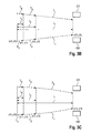
- FIGS. 5A to 5C show the case that the operator has selected the steering mode "coordinated steering" and has specified a certain steering angle. Since the steering device 10 of the construction machine approximately meets the Ackermann law, resulting from the specification of the steering angle, the corresponding positions of the wheels. The outside and inside wheels have different steering angle, the steering angle of the outside wheels are smaller than the steering angle of the inside wheels.
- the extensions L 1 , L 2 , L 3 , L 4 of the wheel axles intersect at the center of curvature M, whereby the radii r 1 , r 2 , r 3 , r 4 are given to the trajectories related to the individual wheel planes.
- the arithmetic unit 16 calculates the trajectories T 1 to T 6 , as described in the preceding embodiments, depending on the selected steering mode " coordinated steering" and the set steering angle, with which the movement of the construction machine is described ( Fig. 5A ).
- the trajectories T 1 , to T 6 in the coordinate system (x, y) of the construction machine ( Fig. 5A ) are converted back into the coordinate system (x ', y') of the image recording unit 15 ( Fig. 5B ) as described above. Again, a correction is made with the first and / or second correction function ( Fig. 5C ).
- FIGS. 6A to 6C show the steering mode "crab steering".
- the extensions of the wheel axles do not pass through a center of curvature, but all the axes are substantially parallel to each other.
- the trajectories point in the direction in which the wheels are pointing.
- the wheels on one side and the wheels on the other side are each directed in the same direction. However, they have different steering angles according to the Ackermann law.
- the steering angle ⁇ 2 of the front and rear wheels on one side is smaller than the steering angle ⁇ 1 of the front and rear wheels on the other side.
- the arithmetic unit 16 again calculates the trajectories T 1 to T 6 , which are determined by start and end point.
- the trajectories are in the steering mode "crab steering" not circular arcs, but straights.Since the wheels on one side have a different steering angle than the wheels on the other side to meet the Ackermann law, the directions on the The trajectories determined by the arithmetic unit have a direction lying between the two directions resulting from the different steering angles for the wheel on one side and the wheel on the other side.
- the trajectories T 1 to T 6 are again from the coordinate system (x, y) of the construction machine in the coordinate system (x ', y ') of the image recording unit ( Fig. 6B ). Again, a correction with the first and second correction function ( Fig. 6C ).
Landscapes
- Engineering & Computer Science (AREA)
- Civil Engineering (AREA)
- Structural Engineering (AREA)
- Mining & Mineral Resources (AREA)
- Mechanical Engineering (AREA)
- Architecture (AREA)
- Transportation (AREA)
- Combustion & Propulsion (AREA)
- Chemical & Material Sciences (AREA)
- General Engineering & Computer Science (AREA)
- Closed-Circuit Television Systems (AREA)
- Road Repair (AREA)
- Control Of Position, Course, Altitude, Or Attitude Of Moving Bodies (AREA)
- Steering Control In Accordance With Driving Conditions (AREA)
- Operation Control Of Excavators (AREA)
- Guiding Agricultural Machines (AREA)
Applications Claiming Priority (1)
| Application Number | Priority Date | Filing Date | Title |
|---|---|---|---|
| DE102010048185.8A DE102010048185B4 (de) | 2010-10-13 | 2010-10-13 | Selbstfahrende Baumaschine |
Publications (3)
| Publication Number | Publication Date |
|---|---|
| EP2441888A2 true EP2441888A2 (fr) | 2012-04-18 |
| EP2441888A3 EP2441888A3 (fr) | 2016-12-07 |
| EP2441888B1 EP2441888B1 (fr) | 2019-03-06 |
Family
ID=44785158
Family Applications (1)
| Application Number | Title | Priority Date | Filing Date |
|---|---|---|---|
| EP11008191.6A Active EP2441888B1 (fr) | 2010-10-13 | 2011-10-11 | Engin automobile |
Country Status (6)
| Country | Link |
|---|---|
| US (1) | US8977442B2 (fr) |
| EP (1) | EP2441888B1 (fr) |
| JP (1) | JP5868651B2 (fr) |
| CN (2) | CN102442251B (fr) |
| AU (1) | AU2011224053B2 (fr) |
| DE (1) | DE102010048185B4 (fr) |
Cited By (1)
| Publication number | Priority date | Publication date | Assignee | Title |
|---|---|---|---|---|
| EP3845710A1 (fr) | 2019-12-30 | 2021-07-07 | Wirtgen GmbH | Procédé de traitement du sol par enlèvement pourvu d'outil d'enlèvement incliné par rapport à la direction d'avancement et machine de traitement du sol conçue pour mettre en oeuvre ledit procédé |
Families Citing this family (19)
| Publication number | Priority date | Publication date | Assignee | Title |
|---|---|---|---|---|
| DE102010048185B4 (de) * | 2010-10-13 | 2021-10-28 | Wirtgen Gmbh | Selbstfahrende Baumaschine |
| DE102012001289A1 (de) * | 2012-01-25 | 2013-07-25 | Wirtgen Gmbh | Selbstfahrende Baumaschine und Verfahren zum Steuern einer selbstfahrenden Baumaschine |
| DE102013006464B4 (de) * | 2012-04-16 | 2020-03-19 | Bomag Gmbh | Baumaschine mit einer Manövriereinrichtung, Verfahren zur Erleichterung des Manövrierens einer Baumaschine und Manövriereinrichtung für eine Baumaschine |
| CN102975769B (zh) * | 2012-12-18 | 2015-08-19 | 山推工程机械股份有限公司 | 一种轮胎式摊铺机及其前桥 |
| CN103661599B (zh) * | 2013-12-04 | 2016-01-06 | 奇瑞汽车股份有限公司 | 一种车辆转弯轨迹预测系统和方法 |
| JP5938057B2 (ja) * | 2014-03-28 | 2016-06-22 | 株式会社ショーワ | 車高調整装置、車高調整装置用の制御装置およびプログラム |
| DE102014012836B4 (de) | 2014-08-28 | 2018-09-13 | Wirtgen Gmbh | Selbstfahrende Baumaschine und Verfahren zur Visualisierung des Bearbeitungsumfeldes einer sich im Gelände bewegenden Baumaschine |
| DE102014012825A1 (de) | 2014-08-28 | 2016-03-03 | Wirtgen Gmbh | Selbstfahrende Baumaschine und Verfahren zur Steuerung einer selbstfahrenden Baumaschine |
| DE102014012831B4 (de) | 2014-08-28 | 2018-10-04 | Wirtgen Gmbh | Selbstfahrende Baumaschine und Verfahren zum Steuern einer selbstfahrenden Baumaschine |
| CN104594161B (zh) * | 2014-11-28 | 2016-09-14 | 山推工程机械股份有限公司 | 轮胎摊铺机及其行走控制系统 |
| US10543782B2 (en) * | 2017-12-19 | 2020-01-28 | Caterpillar Paving Products Inc. | Cutting tool visual trajectory representation system and method |
| DE102018119962A1 (de) | 2018-08-16 | 2020-02-20 | Wirtgen Gmbh | Selbstfahrende Baumaschine und Verfahren zum Steuern einer selbstfahrenden Baumaschine |
| DE102019118059A1 (de) | 2019-07-04 | 2021-01-07 | Wirtgen Gmbh | Selbstfahrende Baumaschine und Verfahren zum Steuern einer selbstfahrenden Baumaschine |
| US11091887B1 (en) | 2020-02-04 | 2021-08-17 | Caterpillar Paving Products Inc. | Machine for milling pavement and method of operation |
| US11619012B2 (en) * | 2020-06-18 | 2023-04-04 | Caterpillar Paving Products Inc. | Rotor depth visual indication zones |
| DE102020210741A1 (de) | 2020-08-25 | 2022-03-03 | Robert Bosch Gesellschaft mit beschränkter Haftung | Verfahren zum Ausgeben eines Steuersignals an eine Einheit eines Fahrzeugs |
| US11590892B2 (en) * | 2021-07-02 | 2023-02-28 | Deere & Company | Work vehicle display systems and methods for generating visually-manipulated context views |
| CN115366883A (zh) * | 2022-09-15 | 2022-11-22 | 长城汽车股份有限公司 | 基于四轮转向的倒车控制方法、装置、存储介质及车辆 |
| CN115402409A (zh) * | 2022-09-16 | 2022-11-29 | 长城汽车股份有限公司 | 一种倒车辅助的方法、装置及车辆 |
Citations (3)
| Publication number | Priority date | Publication date | Assignee | Title |
|---|---|---|---|---|
| DE10334613A1 (de) | 2003-07-29 | 2005-02-17 | Robert Bosch Gmbh | Fahrhilfsvorrichtung |
| WO2007031531A1 (fr) | 2005-09-12 | 2007-03-22 | Wirtgen Gmbh | Engin de chantier autotracte, et colonne de levage d'un engin de chantier |
| WO2008012109A1 (fr) | 2006-07-28 | 2008-01-31 | Universität Koblenz-Landau | Dispositif d'assistance au conducteur pour l'émission des données du véhicule |
Family Cites Families (18)
| Publication number | Priority date | Publication date | Assignee | Title |
|---|---|---|---|---|
| CA1287147C (fr) * | 1985-10-24 | 1991-07-30 | Hiromu Fujimoto | Tracteur equipe d'accessoires de travail |
| US5670935A (en) * | 1993-02-26 | 1997-09-23 | Donnelly Corporation | Rearview vision system for vehicle including panoramic view |
| US5484227A (en) | 1993-04-09 | 1996-01-16 | Niigata Engineering Co., Ltd. | Control device for asphalt finisher |
| US5973733A (en) * | 1995-05-31 | 1999-10-26 | Texas Instruments Incorporated | Video stabilization system and method |
| KR100568396B1 (ko) * | 1998-10-08 | 2006-04-05 | 마츠시타 덴끼 산교 가부시키가이샤 | 운전조작 보조장치 |
| JP4096445B2 (ja) * | 1999-03-31 | 2008-06-04 | アイシン精機株式会社 | 駐車補助装置 |
| GB9929870D0 (en) * | 1999-12-18 | 2000-02-09 | Roke Manor Research | Improvements in or relating to security camera systems |
| EP1158803A3 (fr) * | 2000-05-24 | 2003-12-10 | Matsushita Electric Industrial Co., Ltd. | Appareil de rendu pour produire une image à afficher |
| EP1160146B2 (fr) * | 2000-05-30 | 2013-07-24 | Aisin Seiki Kabushiki Kaisha | Assistance au parking |
| EP1167120B1 (fr) * | 2000-06-30 | 2014-08-27 | Panasonic Corporation | Dispositif de rendu pour faciliter le stationnement d'un véhicule |
| JP4561456B2 (ja) * | 2005-04-21 | 2010-10-13 | アイシン・エィ・ダブリュ株式会社 | 駐車支援方法及び駐車支援装置 |
| WO2008042244A2 (fr) * | 2006-09-29 | 2008-04-10 | Volvo Construction Equipment Ab | systÈme de direction et de propulsion pour une FRAISEUSE ROUTIÈRE |
| DE102007007970B4 (de) * | 2007-02-17 | 2009-11-26 | Wirtgen Gmbh | Baumaschine, insbesondere Straßenbaumaschine |
| DE202007005756U1 (de) * | 2007-04-19 | 2008-08-28 | Wirtgen Gmbh | Selbstfahrende Baumaschine |
| TW200927537A (en) * | 2007-12-28 | 2009-07-01 | Altek Corp | Automobile backup radar system that displays bird's-eye view image of automobile |
| JP4433060B2 (ja) * | 2008-02-18 | 2010-03-17 | トヨタ自動車株式会社 | 駐車支援装置 |
| US20120016555A1 (en) * | 2010-07-18 | 2012-01-19 | Maher Ghneim | Method and system for parking assist |
| DE102010048185B4 (de) * | 2010-10-13 | 2021-10-28 | Wirtgen Gmbh | Selbstfahrende Baumaschine |
-
2010
- 2010-10-13 DE DE102010048185.8A patent/DE102010048185B4/de active Active
-
2011
- 2011-09-14 AU AU2011224053A patent/AU2011224053B2/en active Active
- 2011-10-10 US US13/269,816 patent/US8977442B2/en active Active
- 2011-10-11 EP EP11008191.6A patent/EP2441888B1/fr active Active
- 2011-10-13 JP JP2011225544A patent/JP5868651B2/ja active Active
- 2011-10-13 CN CN201110310568.XA patent/CN102442251B/zh active Active
- 2011-10-13 CN CN2011203900013U patent/CN202294959U/zh not_active Withdrawn - After Issue
Patent Citations (3)
| Publication number | Priority date | Publication date | Assignee | Title |
|---|---|---|---|---|
| DE10334613A1 (de) | 2003-07-29 | 2005-02-17 | Robert Bosch Gmbh | Fahrhilfsvorrichtung |
| WO2007031531A1 (fr) | 2005-09-12 | 2007-03-22 | Wirtgen Gmbh | Engin de chantier autotracte, et colonne de levage d'un engin de chantier |
| WO2008012109A1 (fr) | 2006-07-28 | 2008-01-31 | Universität Koblenz-Landau | Dispositif d'assistance au conducteur pour l'émission des données du véhicule |
Cited By (3)
| Publication number | Priority date | Publication date | Assignee | Title |
|---|---|---|---|---|
| EP3845710A1 (fr) | 2019-12-30 | 2021-07-07 | Wirtgen GmbH | Procédé de traitement du sol par enlèvement pourvu d'outil d'enlèvement incliné par rapport à la direction d'avancement et machine de traitement du sol conçue pour mettre en oeuvre ledit procédé |
| US11802384B2 (en) | 2019-12-30 | 2023-10-31 | Wirtgen Gmbh | Removing earth working method with a removing tool offset obliquely with respect to the propulsion direction, and earth working machine embodied to execute the method |
| US12264443B2 (en) | 2019-12-30 | 2025-04-01 | Wirtgen Gmbh | Removing earth working method with a removing tool offset obliquely with respect to the propulsion direction, and earth working machine embodied to execute the method |
Also Published As
| Publication number | Publication date |
|---|---|
| CN102442251A (zh) | 2012-05-09 |
| US8977442B2 (en) | 2015-03-10 |
| EP2441888A3 (fr) | 2016-12-07 |
| CN202294959U (zh) | 2012-07-04 |
| US20120090909A1 (en) | 2012-04-19 |
| EP2441888B1 (fr) | 2019-03-06 |
| JP2012132298A (ja) | 2012-07-12 |
| CN102442251B (zh) | 2015-05-20 |
| AU2011224053A1 (en) | 2012-05-03 |
| DE102010048185B4 (de) | 2021-10-28 |
| JP5868651B2 (ja) | 2016-02-24 |
| DE102010048185A1 (de) | 2012-04-19 |
| AU2011224053B2 (en) | 2015-07-02 |
Similar Documents
| Publication | Publication Date | Title |
|---|---|---|
| EP2441888B1 (fr) | Engin automobile | |
| DE102015104472B4 (de) | Fahrspurabweichungsverhinderung-Steuerungsvorrichtung für ein Fahrzeug | |
| EP3219533B1 (fr) | Système de vision pour un véhicule, notamment pour un véhicule utilitaire | |
| DE102013107714B4 (de) | Servolenkungsteuerungseinrichtung für ein Fahrzeug | |
| DE60038467T2 (de) | Lenkhilfseinrichtung | |
| DE102015104459B4 (de) | Fahrspurabweichungsverhinderung-Steuerungsvorrichtung für ein Fahrzeug | |
| EP2185400B1 (fr) | Procédé et dispositif d'assistance aidant le conducteur à manoeuvrer un véhicule ou train de véhicules | |
| EP2620547B1 (fr) | Engin automobile et procédé de commande d'un engin automobile | |
| DE112013002543B4 (de) | Displayvorrichtung für Industriemaschine mit Eigenantrieb | |
| DE10065230A1 (de) | Verfahren und System zur Erleichterung des Manövrierens und/oder Rückwärtsfahren eines Fahrzeuges mit einem Anhänger | |
| DE102018123646A1 (de) | Adaptive lenksteuerung für robustheit gegenüber fehlern bei geschätzten oder vom benutzer bereitgestellten anhängerparametern | |
| DE102008043675A1 (de) | Verfahren und Steuergerät zur Bestimmung von Soll-Lenkwinkel eines mehrgliedrigen Fahrzeuggespanns | |
| DE102012102052B4 (de) | Fahrzeugservolenkungssteuerungsvorrichtung | |
| DE102017108804A1 (de) | Anhängerrückfahrunterstützungseingabe mit zweistufiger federrate | |
| DE10065327A1 (de) | Lenkhilfsvorrichtung | |
| DE102013016342A1 (de) | Verfahren zum assistierten Rückwärtsfahren eines Gespanns, Fahrerassistenzsystem | |
| DE102005043466A1 (de) | Rückfahrhilfesystem und Verfahren zur Unterstützung des Fahrers eines Zugfahrzeug-Anhänger-Gespanns bei einer Rückwärtsfahrt | |
| DE102012215005A1 (de) | Selbstfahrende Fräsmaschine, sowie Verfahren zum Lenken einer selbstfahrenden Fräsmaschine | |
| DE102019117132A1 (de) | System und verfahren zur erkennung von und reaktion auf störung zwischen anhängerverbindungsstück und anhängerkupplungskugel | |
| DE102016119897B4 (de) | Geschwindigkeitssteuerung für Kraftfahrzeuge | |
| EP1657140A2 (fr) | Système de direction pour un véhicule | |
| DE102005034883A1 (de) | Fahrunterstützungsvorrichtung | |
| DE112019003544T5 (de) | Lenksteuervorrichtung, lenksteuerverfahren und lenksystem | |
| DE102019129831A1 (de) | Automatisches kupplungssystem mit auswahl des betreffenden anhängers aus mehreren identifizierten anhängern | |
| DE102020122875A1 (de) | Modifizierter lenkwinkel bei abschluss eines kupplungsunterstützungsvorgangs |
Legal Events
| Date | Code | Title | Description |
|---|---|---|---|
| PUAI | Public reference made under article 153(3) epc to a published international application that has entered the european phase |
Free format text: ORIGINAL CODE: 0009012 |
|
| AK | Designated contracting states |
Kind code of ref document: A2 Designated state(s): AL AT BE BG CH CY CZ DE DK EE ES FI FR GB GR HR HU IE IS IT LI LT LU LV MC MK MT NL NO PL PT RO RS SE SI SK SM TR |
|
| AX | Request for extension of the european patent |
Extension state: BA ME |
|
| PUAL | Search report despatched |
Free format text: ORIGINAL CODE: 0009013 |
|
| AK | Designated contracting states |
Kind code of ref document: A3 Designated state(s): AL AT BE BG CH CY CZ DE DK EE ES FI FR GB GR HR HU IE IS IT LI LT LU LV MC MK MT NL NO PL PT RO RS SE SI SK SM TR |
|
| AX | Request for extension of the european patent |
Extension state: BA ME |
|
| RIC1 | Information provided on ipc code assigned before grant |
Ipc: E01C 23/088 20060101AFI20161028BHEP Ipc: B62D 15/02 20060101ALI20161028BHEP |
|
| STAA | Information on the status of an ep patent application or granted ep patent |
Free format text: STATUS: REQUEST FOR EXAMINATION WAS MADE |
|
| 17P | Request for examination filed |
Effective date: 20170607 |
|
| RBV | Designated contracting states (corrected) |
Designated state(s): AL AT BE BG CH CY CZ DE DK EE ES FI FR GB GR HR HU IE IS IT LI LT LU LV MC MK MT NL NO PL PT RO RS SE SI SK SM TR |
|
| STAA | Information on the status of an ep patent application or granted ep patent |
Free format text: STATUS: EXAMINATION IS IN PROGRESS |
|
| 17Q | First examination report despatched |
Effective date: 20180430 |
|
| GRAP | Despatch of communication of intention to grant a patent |
Free format text: ORIGINAL CODE: EPIDOSNIGR1 |
|
| STAA | Information on the status of an ep patent application or granted ep patent |
Free format text: STATUS: GRANT OF PATENT IS INTENDED |
|
| INTG | Intention to grant announced |
Effective date: 20180921 |
|
| GRAS | Grant fee paid |
Free format text: ORIGINAL CODE: EPIDOSNIGR3 |
|
| GRAA | (expected) grant |
Free format text: ORIGINAL CODE: 0009210 |
|
| STAA | Information on the status of an ep patent application or granted ep patent |
Free format text: STATUS: THE PATENT HAS BEEN GRANTED |
|
| AK | Designated contracting states |
Kind code of ref document: B1 Designated state(s): AL AT BE BG CH CY CZ DE DK EE ES FI FR GB GR HR HU IE IS IT LI LT LU LV MC MK MT NL NO PL PT RO RS SE SI SK SM TR |
|
| REG | Reference to a national code |
Ref country code: GB Ref legal event code: FG4D Free format text: NOT ENGLISH |
|
| REG | Reference to a national code |
Ref country code: CH Ref legal event code: EP Ref country code: AT Ref legal event code: REF Ref document number: 1104740 Country of ref document: AT Kind code of ref document: T Effective date: 20190315 |
|
| REG | Reference to a national code |
Ref country code: DE Ref legal event code: R096 Ref document number: 502011015432 Country of ref document: DE |
|
| REG | Reference to a national code |
Ref country code: IE Ref legal event code: FG4D Free format text: LANGUAGE OF EP DOCUMENT: GERMAN |
|
| REG | Reference to a national code |
Ref country code: SE Ref legal event code: TRGR |
|
| REG | Reference to a national code |
Ref country code: NL Ref legal event code: MP Effective date: 20190306 |
|
| REG | Reference to a national code |
Ref country code: LT Ref legal event code: MG4D |
|
| PG25 | Lapsed in a contracting state [announced via postgrant information from national office to epo] |
Ref country code: LT Free format text: LAPSE BECAUSE OF FAILURE TO SUBMIT A TRANSLATION OF THE DESCRIPTION OR TO PAY THE FEE WITHIN THE PRESCRIBED TIME-LIMIT Effective date: 20190306 Ref country code: NO Free format text: LAPSE BECAUSE OF FAILURE TO SUBMIT A TRANSLATION OF THE DESCRIPTION OR TO PAY THE FEE WITHIN THE PRESCRIBED TIME-LIMIT Effective date: 20190606 Ref country code: FI Free format text: LAPSE BECAUSE OF FAILURE TO SUBMIT A TRANSLATION OF THE DESCRIPTION OR TO PAY THE FEE WITHIN THE PRESCRIBED TIME-LIMIT Effective date: 20190306 |
|
| PG25 | Lapsed in a contracting state [announced via postgrant information from national office to epo] |
Ref country code: GR Free format text: LAPSE BECAUSE OF FAILURE TO SUBMIT A TRANSLATION OF THE DESCRIPTION OR TO PAY THE FEE WITHIN THE PRESCRIBED TIME-LIMIT Effective date: 20190607 Ref country code: BG Free format text: LAPSE BECAUSE OF FAILURE TO SUBMIT A TRANSLATION OF THE DESCRIPTION OR TO PAY THE FEE WITHIN THE PRESCRIBED TIME-LIMIT Effective date: 20190606 Ref country code: HR Free format text: LAPSE BECAUSE OF FAILURE TO SUBMIT A TRANSLATION OF THE DESCRIPTION OR TO PAY THE FEE WITHIN THE PRESCRIBED TIME-LIMIT Effective date: 20190306 Ref country code: RS Free format text: LAPSE BECAUSE OF FAILURE TO SUBMIT A TRANSLATION OF THE DESCRIPTION OR TO PAY THE FEE WITHIN THE PRESCRIBED TIME-LIMIT Effective date: 20190306 Ref country code: LV Free format text: LAPSE BECAUSE OF FAILURE TO SUBMIT A TRANSLATION OF THE DESCRIPTION OR TO PAY THE FEE WITHIN THE PRESCRIBED TIME-LIMIT Effective date: 20190306 Ref country code: NL Free format text: LAPSE BECAUSE OF FAILURE TO SUBMIT A TRANSLATION OF THE DESCRIPTION OR TO PAY THE FEE WITHIN THE PRESCRIBED TIME-LIMIT Effective date: 20190306 |
|
| PG25 | Lapsed in a contracting state [announced via postgrant information from national office to epo] |
Ref country code: RO Free format text: LAPSE BECAUSE OF FAILURE TO SUBMIT A TRANSLATION OF THE DESCRIPTION OR TO PAY THE FEE WITHIN THE PRESCRIBED TIME-LIMIT Effective date: 20190306 Ref country code: SK Free format text: LAPSE BECAUSE OF FAILURE TO SUBMIT A TRANSLATION OF THE DESCRIPTION OR TO PAY THE FEE WITHIN THE PRESCRIBED TIME-LIMIT Effective date: 20190306 Ref country code: CZ Free format text: LAPSE BECAUSE OF FAILURE TO SUBMIT A TRANSLATION OF THE DESCRIPTION OR TO PAY THE FEE WITHIN THE PRESCRIBED TIME-LIMIT Effective date: 20190306 Ref country code: PT Free format text: LAPSE BECAUSE OF FAILURE TO SUBMIT A TRANSLATION OF THE DESCRIPTION OR TO PAY THE FEE WITHIN THE PRESCRIBED TIME-LIMIT Effective date: 20190706 Ref country code: ES Free format text: LAPSE BECAUSE OF FAILURE TO SUBMIT A TRANSLATION OF THE DESCRIPTION OR TO PAY THE FEE WITHIN THE PRESCRIBED TIME-LIMIT Effective date: 20190306 Ref country code: AL Free format text: LAPSE BECAUSE OF FAILURE TO SUBMIT A TRANSLATION OF THE DESCRIPTION OR TO PAY THE FEE WITHIN THE PRESCRIBED TIME-LIMIT Effective date: 20190306 Ref country code: EE Free format text: LAPSE BECAUSE OF FAILURE TO SUBMIT A TRANSLATION OF THE DESCRIPTION OR TO PAY THE FEE WITHIN THE PRESCRIBED TIME-LIMIT Effective date: 20190306 |
|
| PG25 | Lapsed in a contracting state [announced via postgrant information from national office to epo] |
Ref country code: SM Free format text: LAPSE BECAUSE OF FAILURE TO SUBMIT A TRANSLATION OF THE DESCRIPTION OR TO PAY THE FEE WITHIN THE PRESCRIBED TIME-LIMIT Effective date: 20190306 Ref country code: PL Free format text: LAPSE BECAUSE OF FAILURE TO SUBMIT A TRANSLATION OF THE DESCRIPTION OR TO PAY THE FEE WITHIN THE PRESCRIBED TIME-LIMIT Effective date: 20190306 |
|
| REG | Reference to a national code |
Ref country code: DE Ref legal event code: R097 Ref document number: 502011015432 Country of ref document: DE |
|
| PG25 | Lapsed in a contracting state [announced via postgrant information from national office to epo] |
Ref country code: IS Free format text: LAPSE BECAUSE OF FAILURE TO SUBMIT A TRANSLATION OF THE DESCRIPTION OR TO PAY THE FEE WITHIN THE PRESCRIBED TIME-LIMIT Effective date: 20190706 |
|
| PLBE | No opposition filed within time limit |
Free format text: ORIGINAL CODE: 0009261 |
|
| STAA | Information on the status of an ep patent application or granted ep patent |
Free format text: STATUS: NO OPPOSITION FILED WITHIN TIME LIMIT |
|
| PG25 | Lapsed in a contracting state [announced via postgrant information from national office to epo] |
Ref country code: DK Free format text: LAPSE BECAUSE OF FAILURE TO SUBMIT A TRANSLATION OF THE DESCRIPTION OR TO PAY THE FEE WITHIN THE PRESCRIBED TIME-LIMIT Effective date: 20190306 |
|
| 26N | No opposition filed |
Effective date: 20191209 |
|
| PG25 | Lapsed in a contracting state [announced via postgrant information from national office to epo] |
Ref country code: SI Free format text: LAPSE BECAUSE OF FAILURE TO SUBMIT A TRANSLATION OF THE DESCRIPTION OR TO PAY THE FEE WITHIN THE PRESCRIBED TIME-LIMIT Effective date: 20190306 |
|
| PG25 | Lapsed in a contracting state [announced via postgrant information from national office to epo] |
Ref country code: TR Free format text: LAPSE BECAUSE OF FAILURE TO SUBMIT A TRANSLATION OF THE DESCRIPTION OR TO PAY THE FEE WITHIN THE PRESCRIBED TIME-LIMIT Effective date: 20190306 |
|
| PG25 | Lapsed in a contracting state [announced via postgrant information from national office to epo] |
Ref country code: MC Free format text: LAPSE BECAUSE OF FAILURE TO SUBMIT A TRANSLATION OF THE DESCRIPTION OR TO PAY THE FEE WITHIN THE PRESCRIBED TIME-LIMIT Effective date: 20190306 |
|
| REG | Reference to a national code |
Ref country code: CH Ref legal event code: PL |
|
| PG25 | Lapsed in a contracting state [announced via postgrant information from national office to epo] |
Ref country code: LI Free format text: LAPSE BECAUSE OF NON-PAYMENT OF DUE FEES Effective date: 20191031 Ref country code: CH Free format text: LAPSE BECAUSE OF NON-PAYMENT OF DUE FEES Effective date: 20191031 Ref country code: LU Free format text: LAPSE BECAUSE OF NON-PAYMENT OF DUE FEES Effective date: 20191011 |
|
| REG | Reference to a national code |
Ref country code: BE Ref legal event code: MM Effective date: 20191031 |
|
| PG25 | Lapsed in a contracting state [announced via postgrant information from national office to epo] |
Ref country code: BE Free format text: LAPSE BECAUSE OF NON-PAYMENT OF DUE FEES Effective date: 20191031 |
|
| PG25 | Lapsed in a contracting state [announced via postgrant information from national office to epo] |
Ref country code: IE Free format text: LAPSE BECAUSE OF NON-PAYMENT OF DUE FEES Effective date: 20191011 |
|
| REG | Reference to a national code |
Ref country code: AT Ref legal event code: MM01 Ref document number: 1104740 Country of ref document: AT Kind code of ref document: T Effective date: 20191011 |
|
| PG25 | Lapsed in a contracting state [announced via postgrant information from national office to epo] |
Ref country code: AT Free format text: LAPSE BECAUSE OF NON-PAYMENT OF DUE FEES Effective date: 20191011 |
|
| PG25 | Lapsed in a contracting state [announced via postgrant information from national office to epo] |
Ref country code: CY Free format text: LAPSE BECAUSE OF FAILURE TO SUBMIT A TRANSLATION OF THE DESCRIPTION OR TO PAY THE FEE WITHIN THE PRESCRIBED TIME-LIMIT Effective date: 20190306 |
|
| PG25 | Lapsed in a contracting state [announced via postgrant information from national office to epo] |
Ref country code: MT Free format text: LAPSE BECAUSE OF FAILURE TO SUBMIT A TRANSLATION OF THE DESCRIPTION OR TO PAY THE FEE WITHIN THE PRESCRIBED TIME-LIMIT Effective date: 20190306 Ref country code: HU Free format text: LAPSE BECAUSE OF FAILURE TO SUBMIT A TRANSLATION OF THE DESCRIPTION OR TO PAY THE FEE WITHIN THE PRESCRIBED TIME-LIMIT; INVALID AB INITIO Effective date: 20111011 |
|
| PG25 | Lapsed in a contracting state [announced via postgrant information from national office to epo] |
Ref country code: MK Free format text: LAPSE BECAUSE OF FAILURE TO SUBMIT A TRANSLATION OF THE DESCRIPTION OR TO PAY THE FEE WITHIN THE PRESCRIBED TIME-LIMIT Effective date: 20190306 |
|
| P01 | Opt-out of the competence of the unified patent court (upc) registered |
Effective date: 20230525 |
|
| PGFP | Annual fee paid to national office [announced via postgrant information from national office to epo] |
Ref country code: DE Payment date: 20251020 Year of fee payment: 15 |
|
| PGFP | Annual fee paid to national office [announced via postgrant information from national office to epo] |
Ref country code: GB Payment date: 20251024 Year of fee payment: 15 |
|
| PGFP | Annual fee paid to national office [announced via postgrant information from national office to epo] |
Ref country code: IT Payment date: 20251031 Year of fee payment: 15 |
|
| PGFP | Annual fee paid to national office [announced via postgrant information from national office to epo] |
Ref country code: FR Payment date: 20251024 Year of fee payment: 15 |
|
| PGFP | Annual fee paid to national office [announced via postgrant information from national office to epo] |
Ref country code: SE Payment date: 20251023 Year of fee payment: 15 |