EP2442074B1 - Elektrisch betriebenes fahrzeug - Google Patents
Elektrisch betriebenes fahrzeug Download PDFInfo
- Publication number
- EP2442074B1 EP2442074B1 EP10792806.1A EP10792806A EP2442074B1 EP 2442074 B1 EP2442074 B1 EP 2442074B1 EP 10792806 A EP10792806 A EP 10792806A EP 2442074 B1 EP2442074 B1 EP 2442074B1
- Authority
- EP
- European Patent Office
- Prior art keywords
- vehicle
- generating unit
- power generating
- condition
- estimated
- Prior art date
- Legal status (The legal status is an assumption and is not a legal conclusion. Google has not performed a legal analysis and makes no representation as to the accuracy of the status listed.)
- Not-in-force
Links
Images



Classifications
-
- G—PHYSICS
- G01—MEASURING; TESTING
- G01C—MEASURING DISTANCES, LEVELS OR BEARINGS; SURVEYING; NAVIGATION; GYROSCOPIC INSTRUMENTS; PHOTOGRAMMETRY OR VIDEOGRAMMETRY
- G01C21/00—Navigation; Navigational instruments not provided for in groups G01C1/00 - G01C19/00
- G01C21/26—Navigation; Navigational instruments not provided for in groups G01C1/00 - G01C19/00 specially adapted for navigation in a road network
- G01C21/34—Route searching; Route guidance
- G01C21/3453—Special cost functions, i.e. other than distance or default speed limit of road segments
- G01C21/3469—Fuel consumption; Energy use; Emission aspects
-
- B—PERFORMING OPERATIONS; TRANSPORTING
- B60—VEHICLES IN GENERAL
- B60L—PROPULSION OF ELECTRICALLY-PROPELLED VEHICLES; SUPPLYING ELECTRIC POWER FOR AUXILIARY EQUIPMENT OF ELECTRICALLY-PROPELLED VEHICLES; ELECTRODYNAMIC BRAKE SYSTEMS FOR VEHICLES IN GENERAL; MAGNETIC SUSPENSION OR LEVITATION FOR VEHICLES; MONITORING OPERATING VARIABLES OF ELECTRICALLY-PROPELLED VEHICLES; ELECTRIC SAFETY DEVICES FOR ELECTRICALLY-PROPELLED VEHICLES
- B60L15/00—Methods, circuits, or devices for controlling the traction-motor speed of electrically-propelled vehicles
- B60L15/20—Methods, circuits, or devices for controlling the traction-motor speed of electrically-propelled vehicles for control of the vehicle or its driving motor to achieve a desired performance, e.g. speed, torque, programmed variation of speed
- B60L15/2045—Methods, circuits, or devices for controlling the traction-motor speed of electrically-propelled vehicles for control of the vehicle or its driving motor to achieve a desired performance, e.g. speed, torque, programmed variation of speed for optimising the use of energy
-
- B—PERFORMING OPERATIONS; TRANSPORTING
- B60—VEHICLES IN GENERAL
- B60L—PROPULSION OF ELECTRICALLY-PROPELLED VEHICLES; SUPPLYING ELECTRIC POWER FOR AUXILIARY EQUIPMENT OF ELECTRICALLY-PROPELLED VEHICLES; ELECTRODYNAMIC BRAKE SYSTEMS FOR VEHICLES IN GENERAL; MAGNETIC SUSPENSION OR LEVITATION FOR VEHICLES; MONITORING OPERATING VARIABLES OF ELECTRICALLY-PROPELLED VEHICLES; ELECTRIC SAFETY DEVICES FOR ELECTRICALLY-PROPELLED VEHICLES
- B60L50/00—Electric propulsion with power supplied within the vehicle
- B60L50/10—Electric propulsion with power supplied within the vehicle using propulsion power supplied by engine-driven generators, e.g. generators driven by combustion engines
- B60L50/16—Electric propulsion with power supplied within the vehicle using propulsion power supplied by engine-driven generators, e.g. generators driven by combustion engines with provision for separate direct mechanical propulsion
-
- B—PERFORMING OPERATIONS; TRANSPORTING
- B60—VEHICLES IN GENERAL
- B60L—PROPULSION OF ELECTRICALLY-PROPELLED VEHICLES; SUPPLYING ELECTRIC POWER FOR AUXILIARY EQUIPMENT OF ELECTRICALLY-PROPELLED VEHICLES; ELECTRODYNAMIC BRAKE SYSTEMS FOR VEHICLES IN GENERAL; MAGNETIC SUSPENSION OR LEVITATION FOR VEHICLES; MONITORING OPERATING VARIABLES OF ELECTRICALLY-PROPELLED VEHICLES; ELECTRIC SAFETY DEVICES FOR ELECTRICALLY-PROPELLED VEHICLES
- B60L50/00—Electric propulsion with power supplied within the vehicle
- B60L50/50—Electric propulsion with power supplied within the vehicle using propulsion power supplied by batteries or fuel cells
- B60L50/60—Electric propulsion with power supplied within the vehicle using propulsion power supplied by batteries or fuel cells using power supplied by batteries
- B60L50/61—Electric propulsion with power supplied within the vehicle using propulsion power supplied by batteries or fuel cells using power supplied by batteries by batteries charged by engine-driven generators, e.g. series hybrid electric vehicles
- B60L50/62—Electric propulsion with power supplied within the vehicle using propulsion power supplied by batteries or fuel cells using power supplied by batteries by batteries charged by engine-driven generators, e.g. series hybrid electric vehicles charged by low-power generators primarily intended to support the batteries, e.g. range extenders
-
- B—PERFORMING OPERATIONS; TRANSPORTING
- B60—VEHICLES IN GENERAL
- B60L—PROPULSION OF ELECTRICALLY-PROPELLED VEHICLES; SUPPLYING ELECTRIC POWER FOR AUXILIARY EQUIPMENT OF ELECTRICALLY-PROPELLED VEHICLES; ELECTRODYNAMIC BRAKE SYSTEMS FOR VEHICLES IN GENERAL; MAGNETIC SUSPENSION OR LEVITATION FOR VEHICLES; MONITORING OPERATING VARIABLES OF ELECTRICALLY-PROPELLED VEHICLES; ELECTRIC SAFETY DEVICES FOR ELECTRICALLY-PROPELLED VEHICLES
- B60L53/00—Methods of charging batteries, specially adapted for electric vehicles; Charging stations or on-board charging equipment therefor; Exchange of energy storage elements in electric vehicles
- B60L53/10—Methods of charging batteries, specially adapted for electric vehicles; Charging stations or on-board charging equipment therefor; Exchange of energy storage elements in electric vehicles characterised by the energy transfer between the charging station and the vehicle
- B60L53/11—DC charging controlled by the charging station, e.g. mode 4
-
- B—PERFORMING OPERATIONS; TRANSPORTING
- B60—VEHICLES IN GENERAL
- B60L—PROPULSION OF ELECTRICALLY-PROPELLED VEHICLES; SUPPLYING ELECTRIC POWER FOR AUXILIARY EQUIPMENT OF ELECTRICALLY-PROPELLED VEHICLES; ELECTRODYNAMIC BRAKE SYSTEMS FOR VEHICLES IN GENERAL; MAGNETIC SUSPENSION OR LEVITATION FOR VEHICLES; MONITORING OPERATING VARIABLES OF ELECTRICALLY-PROPELLED VEHICLES; ELECTRIC SAFETY DEVICES FOR ELECTRICALLY-PROPELLED VEHICLES
- B60L53/00—Methods of charging batteries, specially adapted for electric vehicles; Charging stations or on-board charging equipment therefor; Exchange of energy storage elements in electric vehicles
- B60L53/60—Monitoring or controlling charging stations
- B60L53/62—Monitoring or controlling charging stations in response to charging parameters, e.g. current, voltage or electrical charge
-
- G—PHYSICS
- G01—MEASURING; TESTING
- G01C—MEASURING DISTANCES, LEVELS OR BEARINGS; SURVEYING; NAVIGATION; GYROSCOPIC INSTRUMENTS; PHOTOGRAMMETRY OR VIDEOGRAMMETRY
- G01C21/00—Navigation; Navigational instruments not provided for in groups G01C1/00 - G01C19/00
- G01C21/26—Navigation; Navigational instruments not provided for in groups G01C1/00 - G01C19/00 specially adapted for navigation in a road network
- G01C21/34—Route searching; Route guidance
- G01C21/36—Input/output arrangements for on-board computers
- G01C21/3697—Output of additional, non-guidance related information, e.g. low fuel level
-
- B—PERFORMING OPERATIONS; TRANSPORTING
- B60—VEHICLES IN GENERAL
- B60L—PROPULSION OF ELECTRICALLY-PROPELLED VEHICLES; SUPPLYING ELECTRIC POWER FOR AUXILIARY EQUIPMENT OF ELECTRICALLY-PROPELLED VEHICLES; ELECTRODYNAMIC BRAKE SYSTEMS FOR VEHICLES IN GENERAL; MAGNETIC SUSPENSION OR LEVITATION FOR VEHICLES; MONITORING OPERATING VARIABLES OF ELECTRICALLY-PROPELLED VEHICLES; ELECTRIC SAFETY DEVICES FOR ELECTRICALLY-PROPELLED VEHICLES
- B60L2220/00—Electrical machine types; Structures or applications thereof
- B60L2220/10—Electrical machine types
- B60L2220/20—DC electrical machines
-
- B—PERFORMING OPERATIONS; TRANSPORTING
- B60—VEHICLES IN GENERAL
- B60L—PROPULSION OF ELECTRICALLY-PROPELLED VEHICLES; SUPPLYING ELECTRIC POWER FOR AUXILIARY EQUIPMENT OF ELECTRICALLY-PROPELLED VEHICLES; ELECTRODYNAMIC BRAKE SYSTEMS FOR VEHICLES IN GENERAL; MAGNETIC SUSPENSION OR LEVITATION FOR VEHICLES; MONITORING OPERATING VARIABLES OF ELECTRICALLY-PROPELLED VEHICLES; ELECTRIC SAFETY DEVICES FOR ELECTRICALLY-PROPELLED VEHICLES
- B60L2240/00—Control parameters of input or output; Target parameters
- B60L2240/60—Navigation input
- B60L2240/62—Vehicle position
- B60L2240/622—Vehicle position by satellite navigation
-
- B—PERFORMING OPERATIONS; TRANSPORTING
- B60—VEHICLES IN GENERAL
- B60L—PROPULSION OF ELECTRICALLY-PROPELLED VEHICLES; SUPPLYING ELECTRIC POWER FOR AUXILIARY EQUIPMENT OF ELECTRICALLY-PROPELLED VEHICLES; ELECTRODYNAMIC BRAKE SYSTEMS FOR VEHICLES IN GENERAL; MAGNETIC SUSPENSION OR LEVITATION FOR VEHICLES; MONITORING OPERATING VARIABLES OF ELECTRICALLY-PROPELLED VEHICLES; ELECTRIC SAFETY DEVICES FOR ELECTRICALLY-PROPELLED VEHICLES
- B60L2240/00—Control parameters of input or output; Target parameters
- B60L2240/60—Navigation input
- B60L2240/64—Road conditions
- B60L2240/642—Slope of road
-
- B—PERFORMING OPERATIONS; TRANSPORTING
- B60—VEHICLES IN GENERAL
- B60L—PROPULSION OF ELECTRICALLY-PROPELLED VEHICLES; SUPPLYING ELECTRIC POWER FOR AUXILIARY EQUIPMENT OF ELECTRICALLY-PROPELLED VEHICLES; ELECTRODYNAMIC BRAKE SYSTEMS FOR VEHICLES IN GENERAL; MAGNETIC SUSPENSION OR LEVITATION FOR VEHICLES; MONITORING OPERATING VARIABLES OF ELECTRICALLY-PROPELLED VEHICLES; ELECTRIC SAFETY DEVICES FOR ELECTRICALLY-PROPELLED VEHICLES
- B60L2240/00—Control parameters of input or output; Target parameters
- B60L2240/60—Navigation input
- B60L2240/64—Road conditions
- B60L2240/645—Type of road
-
- B—PERFORMING OPERATIONS; TRANSPORTING
- B60—VEHICLES IN GENERAL
- B60L—PROPULSION OF ELECTRICALLY-PROPELLED VEHICLES; SUPPLYING ELECTRIC POWER FOR AUXILIARY EQUIPMENT OF ELECTRICALLY-PROPELLED VEHICLES; ELECTRODYNAMIC BRAKE SYSTEMS FOR VEHICLES IN GENERAL; MAGNETIC SUSPENSION OR LEVITATION FOR VEHICLES; MONITORING OPERATING VARIABLES OF ELECTRICALLY-PROPELLED VEHICLES; ELECTRIC SAFETY DEVICES FOR ELECTRICALLY-PROPELLED VEHICLES
- B60L2240/00—Control parameters of input or output; Target parameters
- B60L2240/60—Navigation input
- B60L2240/68—Traffic data
-
- B—PERFORMING OPERATIONS; TRANSPORTING
- B60—VEHICLES IN GENERAL
- B60L—PROPULSION OF ELECTRICALLY-PROPELLED VEHICLES; SUPPLYING ELECTRIC POWER FOR AUXILIARY EQUIPMENT OF ELECTRICALLY-PROPELLED VEHICLES; ELECTRODYNAMIC BRAKE SYSTEMS FOR VEHICLES IN GENERAL; MAGNETIC SUSPENSION OR LEVITATION FOR VEHICLES; MONITORING OPERATING VARIABLES OF ELECTRICALLY-PROPELLED VEHICLES; ELECTRIC SAFETY DEVICES FOR ELECTRICALLY-PROPELLED VEHICLES
- B60L2240/00—Control parameters of input or output; Target parameters
- B60L2240/80—Time limits
-
- B—PERFORMING OPERATIONS; TRANSPORTING
- B60—VEHICLES IN GENERAL
- B60L—PROPULSION OF ELECTRICALLY-PROPELLED VEHICLES; SUPPLYING ELECTRIC POWER FOR AUXILIARY EQUIPMENT OF ELECTRICALLY-PROPELLED VEHICLES; ELECTRODYNAMIC BRAKE SYSTEMS FOR VEHICLES IN GENERAL; MAGNETIC SUSPENSION OR LEVITATION FOR VEHICLES; MONITORING OPERATING VARIABLES OF ELECTRICALLY-PROPELLED VEHICLES; ELECTRIC SAFETY DEVICES FOR ELECTRICALLY-PROPELLED VEHICLES
- B60L2250/00—Driver interactions
- B60L2250/10—Driver interactions by alarm
-
- B—PERFORMING OPERATIONS; TRANSPORTING
- B60—VEHICLES IN GENERAL
- B60L—PROPULSION OF ELECTRICALLY-PROPELLED VEHICLES; SUPPLYING ELECTRIC POWER FOR AUXILIARY EQUIPMENT OF ELECTRICALLY-PROPELLED VEHICLES; ELECTRODYNAMIC BRAKE SYSTEMS FOR VEHICLES IN GENERAL; MAGNETIC SUSPENSION OR LEVITATION FOR VEHICLES; MONITORING OPERATING VARIABLES OF ELECTRICALLY-PROPELLED VEHICLES; ELECTRIC SAFETY DEVICES FOR ELECTRICALLY-PROPELLED VEHICLES
- B60L2250/00—Driver interactions
- B60L2250/16—Driver interactions by display
-
- B—PERFORMING OPERATIONS; TRANSPORTING
- B60—VEHICLES IN GENERAL
- B60L—PROPULSION OF ELECTRICALLY-PROPELLED VEHICLES; SUPPLYING ELECTRIC POWER FOR AUXILIARY EQUIPMENT OF ELECTRICALLY-PROPELLED VEHICLES; ELECTRODYNAMIC BRAKE SYSTEMS FOR VEHICLES IN GENERAL; MAGNETIC SUSPENSION OR LEVITATION FOR VEHICLES; MONITORING OPERATING VARIABLES OF ELECTRICALLY-PROPELLED VEHICLES; ELECTRIC SAFETY DEVICES FOR ELECTRICALLY-PROPELLED VEHICLES
- B60L2250/00—Driver interactions
- B60L2250/18—Driver interactions by enquiring driving style
-
- B—PERFORMING OPERATIONS; TRANSPORTING
- B60—VEHICLES IN GENERAL
- B60L—PROPULSION OF ELECTRICALLY-PROPELLED VEHICLES; SUPPLYING ELECTRIC POWER FOR AUXILIARY EQUIPMENT OF ELECTRICALLY-PROPELLED VEHICLES; ELECTRODYNAMIC BRAKE SYSTEMS FOR VEHICLES IN GENERAL; MAGNETIC SUSPENSION OR LEVITATION FOR VEHICLES; MONITORING OPERATING VARIABLES OF ELECTRICALLY-PROPELLED VEHICLES; ELECTRIC SAFETY DEVICES FOR ELECTRICALLY-PROPELLED VEHICLES
- B60L2260/00—Operating Modes
- B60L2260/40—Control modes
- B60L2260/44—Control modes by parameter estimation
-
- B—PERFORMING OPERATIONS; TRANSPORTING
- B60—VEHICLES IN GENERAL
- B60L—PROPULSION OF ELECTRICALLY-PROPELLED VEHICLES; SUPPLYING ELECTRIC POWER FOR AUXILIARY EQUIPMENT OF ELECTRICALLY-PROPELLED VEHICLES; ELECTRODYNAMIC BRAKE SYSTEMS FOR VEHICLES IN GENERAL; MAGNETIC SUSPENSION OR LEVITATION FOR VEHICLES; MONITORING OPERATING VARIABLES OF ELECTRICALLY-PROPELLED VEHICLES; ELECTRIC SAFETY DEVICES FOR ELECTRICALLY-PROPELLED VEHICLES
- B60L2260/00—Operating Modes
- B60L2260/40—Control modes
- B60L2260/50—Control modes by future state prediction
- B60L2260/52—Control modes by future state prediction drive range estimation, e.g. of estimation of available travel distance
-
- B—PERFORMING OPERATIONS; TRANSPORTING
- B60—VEHICLES IN GENERAL
- B60L—PROPULSION OF ELECTRICALLY-PROPELLED VEHICLES; SUPPLYING ELECTRIC POWER FOR AUXILIARY EQUIPMENT OF ELECTRICALLY-PROPELLED VEHICLES; ELECTRODYNAMIC BRAKE SYSTEMS FOR VEHICLES IN GENERAL; MAGNETIC SUSPENSION OR LEVITATION FOR VEHICLES; MONITORING OPERATING VARIABLES OF ELECTRICALLY-PROPELLED VEHICLES; ELECTRIC SAFETY DEVICES FOR ELECTRICALLY-PROPELLED VEHICLES
- B60L2260/00—Operating Modes
- B60L2260/40—Control modes
- B60L2260/50—Control modes by future state prediction
- B60L2260/54—Energy consumption estimation
-
- Y—GENERAL TAGGING OF NEW TECHNOLOGICAL DEVELOPMENTS; GENERAL TAGGING OF CROSS-SECTIONAL TECHNOLOGIES SPANNING OVER SEVERAL SECTIONS OF THE IPC; TECHNICAL SUBJECTS COVERED BY FORMER USPC CROSS-REFERENCE ART COLLECTIONS [XRACs] AND DIGESTS
- Y02—TECHNOLOGIES OR APPLICATIONS FOR MITIGATION OR ADAPTATION AGAINST CLIMATE CHANGE
- Y02T—CLIMATE CHANGE MITIGATION TECHNOLOGIES RELATED TO TRANSPORTATION
- Y02T10/00—Road transport of goods or passengers
- Y02T10/60—Other road transportation technologies with climate change mitigation effect
- Y02T10/62—Hybrid vehicles
-
- Y—GENERAL TAGGING OF NEW TECHNOLOGICAL DEVELOPMENTS; GENERAL TAGGING OF CROSS-SECTIONAL TECHNOLOGIES SPANNING OVER SEVERAL SECTIONS OF THE IPC; TECHNICAL SUBJECTS COVERED BY FORMER USPC CROSS-REFERENCE ART COLLECTIONS [XRACs] AND DIGESTS
- Y02—TECHNOLOGIES OR APPLICATIONS FOR MITIGATION OR ADAPTATION AGAINST CLIMATE CHANGE
- Y02T—CLIMATE CHANGE MITIGATION TECHNOLOGIES RELATED TO TRANSPORTATION
- Y02T10/00—Road transport of goods or passengers
- Y02T10/60—Other road transportation technologies with climate change mitigation effect
- Y02T10/64—Electric machine technologies in electromobility
-
- Y—GENERAL TAGGING OF NEW TECHNOLOGICAL DEVELOPMENTS; GENERAL TAGGING OF CROSS-SECTIONAL TECHNOLOGIES SPANNING OVER SEVERAL SECTIONS OF THE IPC; TECHNICAL SUBJECTS COVERED BY FORMER USPC CROSS-REFERENCE ART COLLECTIONS [XRACs] AND DIGESTS
- Y02—TECHNOLOGIES OR APPLICATIONS FOR MITIGATION OR ADAPTATION AGAINST CLIMATE CHANGE
- Y02T—CLIMATE CHANGE MITIGATION TECHNOLOGIES RELATED TO TRANSPORTATION
- Y02T10/00—Road transport of goods or passengers
- Y02T10/60—Other road transportation technologies with climate change mitigation effect
- Y02T10/70—Energy storage systems for electromobility, e.g. batteries
-
- Y—GENERAL TAGGING OF NEW TECHNOLOGICAL DEVELOPMENTS; GENERAL TAGGING OF CROSS-SECTIONAL TECHNOLOGIES SPANNING OVER SEVERAL SECTIONS OF THE IPC; TECHNICAL SUBJECTS COVERED BY FORMER USPC CROSS-REFERENCE ART COLLECTIONS [XRACs] AND DIGESTS
- Y02—TECHNOLOGIES OR APPLICATIONS FOR MITIGATION OR ADAPTATION AGAINST CLIMATE CHANGE
- Y02T—CLIMATE CHANGE MITIGATION TECHNOLOGIES RELATED TO TRANSPORTATION
- Y02T10/00—Road transport of goods or passengers
- Y02T10/60—Other road transportation technologies with climate change mitigation effect
- Y02T10/7072—Electromobility specific charging systems or methods for batteries, ultracapacitors, supercapacitors or double-layer capacitors
-
- Y—GENERAL TAGGING OF NEW TECHNOLOGICAL DEVELOPMENTS; GENERAL TAGGING OF CROSS-SECTIONAL TECHNOLOGIES SPANNING OVER SEVERAL SECTIONS OF THE IPC; TECHNICAL SUBJECTS COVERED BY FORMER USPC CROSS-REFERENCE ART COLLECTIONS [XRACs] AND DIGESTS
- Y02—TECHNOLOGIES OR APPLICATIONS FOR MITIGATION OR ADAPTATION AGAINST CLIMATE CHANGE
- Y02T—CLIMATE CHANGE MITIGATION TECHNOLOGIES RELATED TO TRANSPORTATION
- Y02T10/00—Road transport of goods or passengers
- Y02T10/60—Other road transportation technologies with climate change mitigation effect
- Y02T10/72—Electric energy management in electromobility
-
- Y—GENERAL TAGGING OF NEW TECHNOLOGICAL DEVELOPMENTS; GENERAL TAGGING OF CROSS-SECTIONAL TECHNOLOGIES SPANNING OVER SEVERAL SECTIONS OF THE IPC; TECHNICAL SUBJECTS COVERED BY FORMER USPC CROSS-REFERENCE ART COLLECTIONS [XRACs] AND DIGESTS
- Y02—TECHNOLOGIES OR APPLICATIONS FOR MITIGATION OR ADAPTATION AGAINST CLIMATE CHANGE
- Y02T—CLIMATE CHANGE MITIGATION TECHNOLOGIES RELATED TO TRANSPORTATION
- Y02T90/00—Enabling technologies or technologies with a potential or indirect contribution to GHG emissions mitigation
- Y02T90/10—Technologies relating to charging of electric vehicles
- Y02T90/12—Electric charging stations
-
- Y—GENERAL TAGGING OF NEW TECHNOLOGICAL DEVELOPMENTS; GENERAL TAGGING OF CROSS-SECTIONAL TECHNOLOGIES SPANNING OVER SEVERAL SECTIONS OF THE IPC; TECHNICAL SUBJECTS COVERED BY FORMER USPC CROSS-REFERENCE ART COLLECTIONS [XRACs] AND DIGESTS
- Y02—TECHNOLOGIES OR APPLICATIONS FOR MITIGATION OR ADAPTATION AGAINST CLIMATE CHANGE
- Y02T—CLIMATE CHANGE MITIGATION TECHNOLOGIES RELATED TO TRANSPORTATION
- Y02T90/00—Enabling technologies or technologies with a potential or indirect contribution to GHG emissions mitigation
- Y02T90/10—Technologies relating to charging of electric vehicles
- Y02T90/14—Plug-in electric vehicles
-
- Y—GENERAL TAGGING OF NEW TECHNOLOGICAL DEVELOPMENTS; GENERAL TAGGING OF CROSS-SECTIONAL TECHNOLOGIES SPANNING OVER SEVERAL SECTIONS OF THE IPC; TECHNICAL SUBJECTS COVERED BY FORMER USPC CROSS-REFERENCE ART COLLECTIONS [XRACs] AND DIGESTS
- Y02—TECHNOLOGIES OR APPLICATIONS FOR MITIGATION OR ADAPTATION AGAINST CLIMATE CHANGE
- Y02T—CLIMATE CHANGE MITIGATION TECHNOLOGIES RELATED TO TRANSPORTATION
- Y02T90/00—Enabling technologies or technologies with a potential or indirect contribution to GHG emissions mitigation
- Y02T90/10—Technologies relating to charging of electric vehicles
- Y02T90/16—Information or communication technologies improving the operation of electric vehicles
Definitions
- the present invention relates to electric drive vehicles, and more particularly, to an electric drive vehicle in which a power generating unit that charges a battery usable for traveling is installed.
- GB 2 448 972 describes a system and method for controlling the operation of a vehicle traveling to a predetermined destination in which the vehicle has more than one route available to reach the predetermined destination.
- a vehicle's driver operating preferences and operating characteristics for the vehicle such as a predicted time to reach the predetermined destination, predicted fuel economy, shortest route and quickest route are determined for at least some of the routes and one of the routes is selected based at least in part on the determined operating characteristics and the driver's operating preferences.
- An algorithm is used along with weighting factors to operating characteristics to rank the available routes.
- the controller providing informational output indicating the selected route to the user of the vehicle.
- Patent Document 1 As to the electric drive vehicle equipped with the power generating unit, there is disclosed an art that may be related to the invention in terms of controlling the amount of generation that depends on a traveling pattern in, for example, Patent Document 1. There is disclosed an art that may be related to the invention in terms of controlling charge and discharge while predicting a traveling condition of the vehicle in, for example, patent Document 2. There is disclosed an art that may be related to the present invention in terms of detachably installing a power generating unit or a battery for discharge while considering whether to travel around locally or travel a long way in, for example, Patent Document 3.
- an operating condition such as an operating condition having priority given to fuel economy or an operating condition having priority given to output may be set in operation of the power generating unit.
- the battery may not be satisfactorily charged by the power generating unit under a certain operating condition of the power generating unit besides the traveling condition of the vehicle.
- the vehicle may fall in inability to run.
- the present invention has been made in terms of the above-described problems and aims at providing an electric drive vehicle that enables a power generating unit to operate under a given condition and makes it possible to prevent the vehicle from falling in inability to run due to shortage of charge before it happens in a case where the vehicle travels under a predetermined vehicle traveling condition.
- the present invention that intends to solve the above problems is an electric drive vehicle as defined in amended claim 1.
- the present may be preferably configured to include: estimated amount-of-fuel calculating means for calculated an estimated amount of fuel needed to travel under the vehicle traveling condition; and second notification control means for performing a control to notify the driver of the estimated amount of fuel.
- the present invention may be configured to further include: vehicle utilizing condition grasping means for grasping a vehicle utilizing condition; travelable distance calculating means for calculating a travelable distance taking the vehicle utilizing condition into consideration; and third notification control means for performing a control to notify the driver of the estimated travelable distance.
- the present invention it is possible to prevent the vehicle from falling in inability to run due to shortage of charge before it happens in a case where the vehicle travels under the predetermined vehicle traveling condition while operating the power generating unit to operate under the given condition.
- an electric drive vehicle 1 has a vehicle main body 10 on which a power generating unit 11, a battery 12 and an electric motor 13 are mounted.
- the power generating unit 11 is detachably installed in the electric drive vehicle 1.
- the electric drive vehicle 1 with the power generating unit 11 being installed detachably is capable of driving even in a state in which the power generating unit 11 is not installed and an electric connection with the power generating unit 11 is not made.
- the power generating unit 11 is of an engine driven type, and is equipped with an engine 111, a generator 112 and a power generating unit side ECU 113.
- the engine 111 drives the generator 112, which generates alternating current.
- the alternating current thus generated is converted to direct current by a not-illustrated rectifier circuit before being stored in the battery 12.
- the ECU 113A on the power generating unit side is provided for primarily controlling the engine 111.
- a fuel sensor 114 for sensing the amount of remaining fuel of the power generating unit is electrically connected to the ECU 113 on the power generating unit side.
- the battery 12 is a DC battery, and is electrically and detachably connected to the power generating unit 11 via a high-voltage-system wiring, which is a power wiring. Power generated by the power generating unit 11 is stored in the battery 12 via the high-voltage-system wiring.
- the battery 12 may be composed of multiple batteries having a rated voltage of 12 V connected in series.
- the electric motor 12 is a driving source and is a DC motor.
- the electric motor 13 is supplied with power from the battery 12 and rotates an output shaft 14.
- the rotary output is transmitted, via a transmission 15, to a pair of right and left rear wheels 2, which are driving wheels, so that the rear wheels 2 can be driven.
- the electric drive vehicle 1A is of a series hybrid type.
- the electric drive vehicle 1A is equipped, in addition to the pair of right and left rear wheels 2 of the driving wheels, with a pair of right and left front wheels 3 that are steering wheels, a handle 4 for manually steering the front wheels 3, an acceleration pedal 5 for changing the number of revolutions of the electric motor 13, a brake pedal 6 and a brake unit 7 for braking the vehicle, and drum brakes 8, which are coupled with the brake pedal 6 by wires, joined to the brake unit 7 and are provided to the front wheels 2 and the rear wheels 3.
- the acceleration pedal 5 is provided with an acceleration position sensor 25 that senses the amount of depression of the acceleration pedal 5, and the brake pedal 6 is provided with a brake switch 26 that senses whether the brake pedal 6 is depressed or not.
- the electric drive vehicle 1A is further provided with a key switch 21.
- the key switch 21 enables selective switching operation between ON, OFF and ACC.
- the key switch 21 is an operation means configured to issue an operation request to the power generating unit 11 and the electric motor 13. More particularly, when the key switch 21 is ON, the operation request is enabled. When the key switch 21 is OFF, the operation request is disabled. When the key switch 21 is ACC, an electric system is activated. When the key switch 21 is then switched to ON, the activated state is maintained.
- the electric drive vehicle 1 is equipped with a generation stop switch 22, which is an operation means capable of stopping the operation of the power generating unit 11. Instead of the generation stop switch 22, an operation means for issuing an operation request to the power generating unit 11 may be provided separately from the key switch 21.
- the electric drive vehicle 1 is equipped with a navigation system 30.
- the navigation system 30 is an in-vehicle electronic device capable of displaying the current location of the vehicle.
- the navigation system 30 is equipped with a touch panel 3, which is used to display various items of information and is an operation means for realizing various operations.
- the navigation system 30 utilizes a GPS (Global Positioning System), detects the current location of the vehicle by map matching, and causes the detected current location of the vehicle to be displayed on the touch panel 31 together with a peripheral map.
- GPS Global Positioning System
- the navigation system 30 may utilize map information stored in a large-capacity storage medium such as a DVD-ROM.
- the navigation system 30 utilizes VICS (Vehicle Information and Communication System) to obtain road traffic information about a traffic jam and a traffic regulation, and causes it to be displayed on the touch panel 31.
- VICS Vehicle Information and Communication System
- the navigation system 30 is capable of setting a destination by a given operation using the touch panel 31.
- the navigation system 30 in which the destination has been set creates a route for traveling to the destination and causes the traveling route to be displayed on the touch panel 31 so as to be overlaid on the map.
- the navigation system 30 may employ notification of information by voice using a speaker 35 instead of or together with the display on the touch panel 31.
- the electric drive vehicle 1 is equipped with an operating condition setting switch 40 used to set the operating condition of the power generating unit 11.
- the operating condition setting switch 40 may be a switch that changes the operating condition of the power generating unit 11 between an eco-charge mode in which the power generating unit 11 is operated with priority being given to fuel economy and a rapid-charge mode in which the power generating unit 11 is operated with priority being given to output.
- the power generating unit 11 is operated at an optimal operating point in view of fuel economy in the eco-charge mode, and is operated at an operating point at which the maximum output is available.
- the operating condition setting switch 40 is configured to set the operating condition of the power generating unit 11 to the rapid-charge mode. By turning off the operating condition setting switch 40, the operating condition of the power generating unit 11 is set to the eco-charge mode.
- the operating condition of the power generating unit 11 is not limited to the eco-charge mode and the rapid-charge mode, but another operating condition such that fuel economy and output are balanced may be applied to the operating condition of the power generating unit 11.
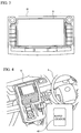
- the operating condition setting switch 40 means for setting the operating condition may be realized by, for example, a touch panel 51 as illustrated in FIG. 5 .
- the operating condition setting switch 40 is not only means for setting the operating condition of the power generating unit 11 but also means for setting a user's intention involved in the operation of the power generating unit 11.
- the electric drive vehicle 1 is equipped with an instrument panel 45. As illustrated in FIG. 6 , on the instrument panel 45, there are provided an alarm lamp 46 for a given alarm, an amount-of-fuel display part 47 as means for showing an estimated amount of fuel for the power generating unit 11 necessary for traveling the route for the destination, and a travelable distance display part 48 as means for showing an estimated travelable distance.
- the electric drive vehicle 1 is equipped with a vehicle-side ECU 50, which is a first control device.
- the ECU 50 on the vehicle side has a microcomputer composed of a CPU, a ROM, a RAM and so on, and an input/output circuit, which are not illustrated.
- the ECU 113 on the power generating unit side which corresponds to a second control device, is configured similarly.
- the power generating unit 11 (more particularly, the ECU 113 on the power generating unit side) is connected electrically and detachably to the ECU 50 on the vehicle side.
- the ECU 50 on the vehicle side and the power generating unit 11 are connected by a low-voltage-system wiring, which is a control-system wiring.
- the navigation system 30 is connected to the ECU 50 on the vehicle side to communicate therewith.
- the navigation system 30 is composed of a microcomputer including a CPU, a ROM, a RAM and so on, and an input/output circuit, which are not illustrated.
- the ROM stores a program in which various processes executed by the CPU are described, and map data.
- the CPU executes the processes based on the program stored in the ROM while utilizing a temporary memory area formed in the RAM as necessary, and functionally realizes various control means, decision making means, detection means and calculating means in the navigation system 30, the ECU 50 on the vehicle side and the ECU 113 on the power generating unit side.
- vehicle traveling condition acquiring means for acquiring a vehicle traveling condition is functionally realized in the navigation system 30.
- the vehicle traveling condition is a traveling condition that influences consumption of the charge stored in the battery 12, and may include at least a travel distance, which is an expected travel distance.
- the vehicle traveling condition may include road information, road traffic information such as a traffic jam, section information, and altitude information.
- the road information may be composed of type of road such as expressway or ordinary road, the width of road, the number of lanes, and the speed limit.
- the section information may be composed of information as to whether the section of interest is a section in which the vehicle is frequently stopped at a read light such as an urban area or a section in which the vehicle is not frequently stopped such as a country area, and information as to whether the section of interest is a mountain area having many up and down slopes.
- the altitude information may include the altitudes and slopes of the roads in given positions.
- the vehicle traveling condition includes more contents
- the vehicle traveling condition acquiring means is realized so as to acquire various vehicle traveling conditions by using map information and VICS.
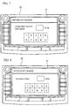
- the vehicle traveling condition acquiring means is not limited to the above but may be realized by the touch panel 31 (see FIG 7 ) configured to have a screen through which the expected travel distance may be input.
- estimation means for estimating the amount of charge in the battery 12 consumed during traveling under the vehicle traveling condition acquired by the vehicle traveling condition acquiring means.
- the estimation means is realized so as to estimate the amount of charge in the battery 12 consumed on the basis of vehicle traveling patterns supposed under the various vehicle traveling conditions.
- the estimation means may be realized so as to estimate the amount of charge in the battery 12 consumed by referring to the average amounts of battery consumption (for example, the average amount of battery consumption per 1 km) respectively associated with given traveling patterns predetermined in, for example, standards.
- an estimated time calculating means for calculating an estimated time necessary for charging the battery 12 to make up the amount of charge estimated by the estimation means when the power generating unit 11 charges the battery 12 on the basis of the operating condition set by the operating condition setting switch 40.
- the amounts of power generations per unit time respectively associated with the operating conditions of the power generating unit 11 are stored in the ROM of the ECU 50 on the vehicle side.
- desired time setting means for setting a desired time it takes to charge the battery 12 to make up the amount of charge estimated by the estimation means is obtained when the power generating unit 11 charges the battery 12 on the basis of the operating condition set by the operating condition setting switch 40.
- the desired time setting means may be realized by the touch panel (see FIG. 8 ) configured to have a screen on which the desired time may be input.
- travel time calculating means capable of calculating the travel time for the destination may be functionally realized by the navigation system 30, and desired time setting means for automatically setting the travel time calculated by the travel time calculating means may be functionally realized.
- first notification control means for performing a control to notify the driver of an alarm when the estimated time calculated by the estimated time calculating means is longer than the desired time set by the desired time setting means.
- the control to notify the driver of the alarm may be realized so that the first notification control means turns on the alarm lamp 46.
- the control to notify the driver of an alarm is not limited to the above but may be, for example, a control so that the first notification control means causes an alarm to be displayed on the touch panel 31, another control to output an alarm by voice through the speaker 35, or a combination of these controls.
- an estimated-amount-of-fuel calculating means for calculating an estimated amount of fuel for the power generating unit 11 necessary to travel under the vehicle traveling condition acquired by the vehicle traveling condition acquiring means. More particularly, the estimated-amount-of-fuel calculating means is realized so as to calculate the amount of fuel necessary for charging the battery 12 to make up the amount of charge estimated by the estimation means when the battery 12 is charged by the power generating unit 11 under the operating condition set by the operating condition setting switch 40.
- the ROM of the ECU 50 on the vehicle side stores correlations between the amounts of power generation and the amounts of fuel consumption in association with the various operating conditions of the power generating unit 11 (which are the echo-charge mode and the rapid-charge mode in the present embodiment).
- a second notification control means for carrying out a control for notification of an estimated amount of fuel is functionally realized in the ECU 50 on the vehicle side. More particularly, the second notification control means may be realized so that the estimated amount of fuel is displayed on the amount-of-fuel display part 47.
- the second notification control means is not limited to the above but may be, for example, a control so that the first notification control means causes the estimated amount of fuel to be displayed on the touch panel 31, another control for outputting the estimated amount of fuel by voice through the speaker 35, or a combination of these controls.
- An estimated travelable distance calculating means for calculating an estimated travelable distance is functionally realized in the ECU 50 on the vehicle side. More particularly, the estimated travelable distance calculating means calculates an available total power on the basis of the state of charge of the battery 12, the amount of remaining fuel for the power generating unit 11, and the operating condition of the power generating unit 11 set by the operating condition setting switch 40, and calculates the average amount of battery consumption (for example, the average amount of battery consumption per 1 km) depending on the vehicle traveling condition on the basis of the vehicle traveling condition acquired by the vehicle traveling condition acquiring means. Further, the estimated travelable distance calculating means divides the total power by the average amount of battery consumption to thus obtain the estimated travelable distance.
- a third notification control means for carrying out a control to notify the driver of the estimated travelable distance is functionally realized in the ECU 50 on the vehicle side. More particularly, the third notification control means is realized so as to carry out a control to cause the estimated travelable distance to be displayed.
- the third notification control means is not limited to the above but may be, for example, a control so that the third notification control means causes the estimated travelable distance to be displayed on the touch panel 31, another control to output the estimated travelable distance by voice through the speaker 35, or a combination of these controls.
- a vehicle utilizing condition grasping means for grasping a vehicle utilizing condition is functionally realized in the ECU 50 on the vehicle side.
- the vehicle utilizing condition may include a utilizing condition that influences the state of charge of the battery 12 consumed during traveling under the vehicle traveling condition, and may include, for example, the status of utilization of an electric component that consumes power of the battery 12 such as an air conditioner, and may include a loaded weight.
- the loaded weight may be grasped from the product of the number of passengers obtained from an output signal of a seating sensor capable of sensing existence or nonexistence of passengers and the average weight, or may be grasped from an output of an air pressure sensor of tires.
- the loaded weight may be grasped by an input operation on the touch panel 31 configured to have an input screen on which the loaded weight can be input.
- the estimation means is realized so as to estimate the amount of charge in the battery 12 consumed when the vehicle travels on the route for the destination by further considering the vehicle utilizing condition grasped by the vehicle utilizing condition grasping means.
- the estimated travelable distance calculating means is realized so as to calculate the estimated travelable distance by further considering the vehicle utilizing condition grasped by the vehicle utilizing condition grasping means.
- the vehicle utilizing condition may be considered by multiply the amount of battery consumption by a coefficient having a value that is predetermined in accordance with the degree of promotion of battery consumption.
- the estimated-amount-of-fuel calculating means is consequently realized so as to consider the vehicle utilizing condition since the estimation means considers the vehicle utilizing condition.
- An operation means for operating the power generating unit 11 under the operating condition set by the operating condition setting switch 40 is functionally realized in the ECU 113 on the power generating unit side.
- the output of the operating condition setting switch 40 is arranged to be applied to the ECU 113 on the power generating unit side via the ECU 50 on the vehicle side.
- the ECU 113 on the power generating unit side is configured to determine whether the operating condition of the power generating unit 11 is in the eco-charge mode or the rapid-charge mode by referring to the output of the operating condition setting switch 40.
- the operation means corresponds to not only the above but also operation means for operating the power generating unit 11 on the basis of a user's intention set by the intention setting means.
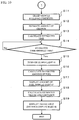
- step S1 the electrical system is activated (step S1). More particularly, at this time, the navigation system 30, the ECU 50 on the vehicle side, and the ECU 113 on the power generating unit side are activated.
- step S2 the ECU 50 on the vehicle side determines whether the key switch 21 is ON (step S2).
- step S3 the ECU 50 on the vehicle side issues an operation request for the power generating unit 11 and the electric motor 13 (step S3).
- step S4 the power generating unit 11 operates in the eco-charge mode or the rapid-charge mode in accordance with the output of the operating condition setting switch 40.
- step S5 determines whether a destination is set.
- step S5 acquires the vehicle traveling condition about the route for traveling to the destination (step S6), and outputs it to the ECU 50 on the vehicle side (step S7).
- the navigation system 30 causes the input screen for inputting the desired time to be displayed on the touch panel 31 (step S8), and determines whether the desired time is set (step S9).
- step S9 the process returns to step S9.
- the desired time is input to the ECU 50 on the vehicle side (step S10).
- step S10 the ECU 50 on the vehicle side grasps the vehicle utilizing condition (step S11). Then, the ECU 50 on the vehicle side estimates the amount of charge in the battery 12 consumed during traveling under the vehicle traveling condition by referring to the operating condition set by the operating condition setting switch 40 and the vehicle traveling condition input from the navigation system 30, while taking the grasped vehicle utilizing condition into consideration (step S12). The ECU 50 on the vehicle side calculates the estimated time necessary for the power generating unit 11 to charge the battery 12 to make up the estimated amount of charge under the operating condition set by the operating condition setting switch 40 (step S 13). The ECU 50 on the vehicle side determines whether the estimated time is longer than the desired time (step S 14), and turns on the alarm lamp 46 if the answer is YES (step S 15).
- step S16 the ECU 50 on the vehicle side calculates the estimated amount of fuel (step S16), and causes the estimated amount of fuel to be displayed on the amount-of-fuel display part 67 (step S17).
- step S18 the estimated travelable distance
- step S 19 the vehicle utilizing condition is considered.
- the functions and effects of the electric drive vehicle 1 are now described.
- the electric drive vehicle 1 is equipped with the operating condition setting switch 50 with which the operating condition of the power generating unit 11 may be input in operation of the power generating unit 11.
- the electric drive vehicle 1 is capable of operating the power generating unit 11 on the basis of a user's intention such that priority should be given to the fuel economy or output.
- the electric drive vehicle 1 is configured to turn on the alarm lamp 46 when the desired time that is set as the expected travel time for the destination is longer than the estimated time.
- the electric drive vehicle 1 it is possible to prevent the electric drive vehicle 1 from falling in inability to run due to shortage of charge before it happens in a situation in which the power generating unit 11 is operating under the specified operating condition and the electric drive vehicle 1 is traveling under the specified vehicle traveling condition. More specifically, the shortage of charge may occur in the case where the operating condition of the power generating unit 11 is the eco-charge mode. It is possible to cope with incomplete charging by switching the operating condition of the power generating unit 11 to the rapid-charge mode.
- the electric drive vehicle 1 may have a supposed case where the power generating unit 11 originally fails to ensure power necessary for arriving at the destination.
- the electric drive vehicle 1 is configured to display the estimated amount of fuel needed by the power generating unit 11 during traveling under the vehicle traveling condition on the amount-of-fuel display part 67.
- the electric drive vehicle 1 is favorable in that it is possible to know whether fuel is short by comparing the actual amount of remaining fuel with the estimated amount of fuel and to prevent the vehicle from falling in inability to run before it happens.
- the estimated amount of fuel may be calculated by preliminarily grasping the operating condition of the power generating unit 11 and performance based on the operating condition.
- the electric drive vehicle 1 is favorable in that calculation and display of the estimated amount of fuel may be applied to a power generating unit that is not configured specifically to communicate with the ECU 50 on the vehicle side.
- the electric drive vehicle 1 may be configured to have necessary information such as an engine displacement, used fuel, fuel on board, thermal efficiency and other factors.
- the electric drive vehicle 1 is favorable in that the estimated travelable distance is displayed on the travelable distance display part 68 so that the vehicle can be prevented from falling in inability to run due to incomplete charging resulting from shortage of fuel before it happens.
- the electric drive vehicle 1 is configured to take the vehicle utilizing condition into consideration in estimation of the amount of charge of the battery 12 consumed during traveling under the vehicle traveling condition, calculation of the estimated amount of fuel and calculation of the estimated travelable distance.
- the electric drive vehicle 1 is prevented from falling in inability to run due to incomplete charging resulting from shortage of fuel before it happens because estimation and calculation may be done more precisely.
- the operating condition setting switch 40 is the intention setting means for setting the user's intention related to the operation of the power generating unit 11 as well as the operating condition setting means capable of setting the operating condition of the power generating unit 11.
- the present invention is not limited to the above but the user's intention set by the intention setting means may be, for example, the desired time of charging by the power generating unit, the travel distance, or a request for operating the air conditioner (which may include temperature setting) besides the operating condition of the power generating unit.
- the operation means operates the power generating unit in accordance with the user's intention.
- the operation means may operate the power generating unit so as to charge the necessary amount of charge in the battery within the desired time (for example, a given amount of charge such as fully charging, or the amount of charge consumed during traveling under the vehicle traveling condition).
- the operation means may operate the power generating unit under the operating condition in which priority is much more given to output as the desired time is shorter. This is favorable because the necessary charging can be completed within the user's desired time.
- the operation means may operate the power generating unit so as to charge the battery to make up an amount of charge consumed depending on the travel distance.
- the operation means may operate the power generating unit under the operating condition in which priority is much more given to the fuel economy as the travel distance is longer. This is favorable in that the battery can be charged with economy in a case where the electric drive vehicle may further be equipped with stop means for stopping the operation of the power generating unit when the operation means completes charging.
- the operation means may operate the power generating unit so as to charge the battery to make up an amount of charge consumed depending on the travel route.
- the operation means may operate the power generating unit under the operating condition in which priority is much more given to the fuel economy as the travel distance is longer or the estimated amount of battery consumption is greater. This is favorable in that the battery can be charged with economy in a case where the electric drive vehicle may further be equipped with stop means for stopping the operation of the power generating unit when the operation means completes charging.
- the operation means may operate the power generating unit so as to charge the battery to make up power necessary to operate the air conditioner in accordance with the request.
- the operation means may operate the power generating unit under the operating condition in which priority is much more given to output as the request for operation is set so as to have an increased load of the air conditioner. This is favorable in that the capacity of the battery can be prevented from being decreased due to the use of the air conditioner.
- the operating condition setting means which is the intention setting means also, may be not only means capable of directly setting the operating condition of the power generating unit but may be means capable of setting the operating condition of the power generating unit based on a predetermined setting.
- the various means that are functionally realized by the navigation system 30, the ECU 50 on the vehicle side and the ECU 113 on the power generating unit side may be realized by, for example, other electronic control devices, hardware such as dedicated electronic circuits or combination thereof.
Landscapes
- Engineering & Computer Science (AREA)
- Radar, Positioning & Navigation (AREA)
- Remote Sensing (AREA)
- Power Engineering (AREA)
- Mechanical Engineering (AREA)
- Transportation (AREA)
- Automation & Control Theory (AREA)
- General Physics & Mathematics (AREA)
- Physics & Mathematics (AREA)
- Sustainable Development (AREA)
- Sustainable Energy (AREA)
- Life Sciences & Earth Sciences (AREA)
- Electric Propulsion And Braking For Vehicles (AREA)
- Navigation (AREA)
- Hybrid Electric Vehicles (AREA)
Claims (3)
- Elektrisch betriebenes Fahrzeug (1), aufweisend:einen Fahrzeughauptkörper (10);eine Batterie (12), die an dem Fahrzeughauptkörper (10) angebracht ist und zum Fahren verwendbar ist; undeine Energieerzeugungseinheit (11), die in dem elektrisch betriebenen Fahrzeug (1) installiert ist und die die Batterie (12) lädt, wobei der elektrische Antrieb (1) sogar in einem Zustand antreiben kann, in dem die Energieerzeugungseinheit (11) nicht installiert ist und eine elektrische Verbindung mit der Energieerzeugungseinheit (11) nicht hergestellt ist, ferner aufweisend:ein Betriebsbedingungsfestlegungsmittel (40), durch das ein Benutzer des elektrisch betriebenen Fahrzeugs eine Betriebsbedingung der Energieerzeugungseinheit (11) auf einen ersten Modus, in dem die Energieerzeugungseinheit (11) mit Priorität auf Kraftstoffwirtschaftlichkeit betrieben wird, und einen zweiten Modus festlegen kann, in dem die Energieerzeugungseinheit (11) mit Priorität auf Ausgabe betrieben wird;ein Betriebsmittel zum Betreiben der Energieerzeugungseinheit (11) unter der Betriebsbedingung, die durch das Betriebsbedingungsfestlegungsmittel (40) festgelegt wird;ein Fahrzeugfahrtbedingungsfestlegungsmittel (30) zum Erlangen einer Fahrzeugfahrtbedingung über eine Route zu einem Ziel des elektrisch betriebenen Fahrzeugs;ein Schätzmittel (50) zum Schätzen, aus der Fahrzeugfahrtbedingung eines Ladebetrags der Batterie (12), der beim Fahren unter der Fahrzeugfahrtbedingung verbraucht wird;dadurch gekennzeichnet, dass die Energieerzeugungseinheit abnehmbar installiert ist, und durch ein Schätzzeitberechnungsmittel (50) zum Berechnen einer geschätzten Zeit, die zum Laden der Batterie notwendig ist, um den Ladebetrag, der durch das Schätzmittel (50) geschätzt wird, unter der Betriebsbedingung durch die Energieerzeugungseinheit (11) auszugleichen;ein Zeitfestlegungsmittel (30), das eine erwartete Zeit zum Ziel festlegen kann; undein erstes Unterrichtungssteuermittel (50) zum Ausführen einer Steuerung zum Unterrichten eines Fahrers über einen Alarm, wenn die geschätzte Zeit, die zum Laden der Batterie (12) notwendig ist, länger als die erwartete Zeit zum Ziel ist.
- Elektrisch betriebenes Fahrzeug gemäß Anspruch 1, ferner gekennzeichnet durch:Schätzkraftstoffbetragsberechnungsmittel (50) zum Berechnen eines geschätzten Kraftstoffbetrags, der zum Fahren unter der Fahrzeugfahrtbedingung benötigt wird; undein zweites Unterrichtungssteuermittel (50) zum Ausführen einer Steuerung zum Unterrichten des Fahrers über den geschätzten Kraftstoffbetrag.
- Elektrisch betriebenes Fahrzeug gemäß Anspruch 1 oder 2, ferner gekennzeichnet durch:ein Fahrzeugverwendungsbedingungserfassungsmittel (50) zum Erfassen einer Fahrzeugverwendungsbedingung;ein Restreichweitenberechnungsmittel (50) zum Berechnen einer Restreichweite unter Berücksichtigung der Fahrzeugverwendungsbedingung; undein drittes Unterrichtungssteuermittel (50) zum Ausführen einer Steuerung zum Unterrichten des Fahrers über die geschätzte Restreichweite.
Applications Claiming Priority (1)
| Application Number | Priority Date | Filing Date | Title |
|---|---|---|---|
| PCT/JP2010/054667 WO2011114486A1 (ja) | 2010-03-18 | 2010-03-18 | 電気駆動式車両 |
Publications (3)
| Publication Number | Publication Date |
|---|---|
| EP2442074A1 EP2442074A1 (de) | 2012-04-18 |
| EP2442074A4 EP2442074A4 (de) | 2014-09-03 |
| EP2442074B1 true EP2442074B1 (de) | 2016-03-16 |
Family
ID=44648615
Family Applications (1)
| Application Number | Title | Priority Date | Filing Date |
|---|---|---|---|
| EP10792806.1A Not-in-force EP2442074B1 (de) | 2010-03-18 | 2010-03-18 | Elektrisch betriebenes fahrzeug |
Country Status (5)
| Country | Link |
|---|---|
| US (1) | US8423219B2 (de) |
| EP (1) | EP2442074B1 (de) |
| JP (1) | JP4930640B2 (de) |
| CN (1) | CN102439396B (de) |
| WO (1) | WO2011114486A1 (de) |
Families Citing this family (22)
| Publication number | Priority date | Publication date | Assignee | Title |
|---|---|---|---|---|
| EP2442074B1 (de) * | 2010-03-18 | 2016-03-16 | Toyota Jidosha Kabushiki Kaisha | Elektrisch betriebenes fahrzeug |
| DE102010029115A1 (de) * | 2010-05-19 | 2011-11-24 | Bayerische Motoren Werke Aktiengesellschaft | Verfahren und Vorrichtung zum Betreiben eines Kraftfahrzeugs |
| DE102010063436A1 (de) * | 2010-12-17 | 2012-06-21 | Robert Bosch Gmbh | Verfahren und Vorrichtung zum Bestimmen einer Reichweite eines Fahrzeugs |
| JP5454739B2 (ja) * | 2011-05-11 | 2014-03-26 | トヨタ自動車株式会社 | 充電制御装置およびそれを備える車両ならびに充電制御方法 |
| JP5775934B2 (ja) * | 2011-09-05 | 2015-09-09 | 本田技研工業株式会社 | 車両の制御装置 |
| US20130166123A1 (en) * | 2011-12-21 | 2013-06-27 | Ford Global Technologies, Llc | Vehicle system for estimating travel range |
| KR101397023B1 (ko) * | 2012-03-23 | 2014-05-20 | 삼성에스디아이 주식회사 | 배터리 팩 및 배터리 팩의 제어 방법 |
| JP5631367B2 (ja) * | 2012-08-09 | 2014-11-26 | 本田技研工業株式会社 | 経路探索装置 |
| US8958936B2 (en) * | 2012-10-19 | 2015-02-17 | Ford Global Technologies, Llc | System override for user selected electric-only operation of a hybrid vehicle |
| US8903579B2 (en) * | 2012-10-19 | 2014-12-02 | Ford Global Technologies, Llc | User override for electric-only operation of a hybrid vehicle |
| JP2014201246A (ja) * | 2013-04-08 | 2014-10-27 | トヨタ自動車株式会社 | ハイブリッド車両 |
| JP2014201245A (ja) * | 2013-04-08 | 2014-10-27 | トヨタ自動車株式会社 | ハイブリッド車両 |
| DE102013219441A1 (de) * | 2013-09-26 | 2015-03-26 | Volkswagen Aktiengesellschaft | Verfahren und Vorrichtung zur Ladeplanung eines Fahrzeugs mit elektrischem Antrieb |
| FR3021613B1 (fr) * | 2014-05-27 | 2017-11-24 | Renault Sas | Procede d'estimation du temps de rehabilitation de la performance d'une batterie de traction d'un vehicule hybride |
| US9711982B2 (en) * | 2015-03-23 | 2017-07-18 | Panasonic Intellectual Property Management Co., Ltd. | Information notifying device |
| KR101916511B1 (ko) * | 2016-05-16 | 2018-11-07 | 현대자동차주식회사 | 차량 시스템 및 차량 시스템의 배터리 충전 방법 |
| WO2019030911A1 (ja) * | 2017-08-10 | 2019-02-14 | 日産自動車株式会社 | ハイブリッド車両の制御方法及び制御装置 |
| EP3666586B1 (de) * | 2017-08-10 | 2024-02-28 | Nissan Motor Co., Ltd. | Verfahren und vorrichtung zur steuerung eines hybridfahrzeugs |
| JP7172201B2 (ja) * | 2018-07-09 | 2022-11-16 | スズキ株式会社 | 発電制御装置 |
| CN110281909B (zh) * | 2019-07-15 | 2020-06-19 | 安阳工学院 | 一种混合动力汽车防亏电自启动系统及其控制方法 |
| JP7433576B2 (ja) * | 2019-12-27 | 2024-02-20 | スズキ株式会社 | 電動車両 |
| JP7769465B2 (ja) * | 2019-12-27 | 2025-11-13 | スズキ株式会社 | 発電制御装置 |
Family Cites Families (31)
| Publication number | Priority date | Publication date | Assignee | Title |
|---|---|---|---|---|
| JP3094772B2 (ja) | 1994-02-21 | 2000-10-03 | トヨタ自動車株式会社 | 発電機を搭載する電気自動車の発電機出力制御装置 |
| JP3211699B2 (ja) | 1996-09-17 | 2001-09-25 | トヨタ自動車株式会社 | 動力出力装置 |
| JP2001211504A (ja) | 2000-01-26 | 2001-08-03 | Shigeo Tanahashi | 電気自動車 |
| JP3758140B2 (ja) * | 2001-07-09 | 2006-03-22 | 日産自動車株式会社 | 情報提示装置 |
| US6814170B2 (en) * | 2001-07-18 | 2004-11-09 | Nissan Motor Co., Ltd. | Hybrid vehicle |
| WO2005068245A1 (ja) | 2004-01-16 | 2005-07-28 | Yamaha Hatsudoki Kabushiki Kaisha | ハイブリッド車両 |
| JP2006112932A (ja) | 2004-10-15 | 2006-04-27 | Fuji Heavy Ind Ltd | 電気自動車のナビゲーションシステム |
| JP4362721B2 (ja) * | 2004-11-12 | 2009-11-11 | 三菱自動車工業株式会社 | ハイブリッド車両 |
| KR101091268B1 (ko) * | 2005-04-25 | 2011-12-07 | 주식회사 엘지화학 | Hev와 ev를 위한 전지팩 관리방법 |
| EP1842758B1 (de) * | 2006-04-03 | 2009-09-02 | Harman Becker Automotive Systems GmbH | Routenbestimmung für ein Hybridfahrzeug und zugehöriges System |
| KR100857370B1 (ko) * | 2006-09-29 | 2008-09-05 | 현대자동차주식회사 | 하이브리드 전기 자동차에서 목표 충전 상태를 이용한 배터리 충전 제어 장치 및 방법 |
| JP2008137543A (ja) * | 2006-12-04 | 2008-06-19 | Toyota Motor Corp | 車両およびその制御方法 |
| JP2008278740A (ja) * | 2007-04-04 | 2008-11-13 | Furukawa Electric Co Ltd:The | 電池状態検知システム |
| JP2008265518A (ja) * | 2007-04-19 | 2008-11-06 | Fujitsu Ten Ltd | 電源管理装置及びプログラム |
| US7865298B2 (en) * | 2007-05-03 | 2011-01-04 | Ford Motor Company | System and method for providing route information to a driver of a vehicle |
| KR20100013313A (ko) * | 2007-05-21 | 2010-02-09 | 주식회사 씨티앤티 | 연료전지-배터리 하이브리드 시스템의 동력분배 제어방법 및 제어장치 |
| JP4760779B2 (ja) * | 2007-06-13 | 2011-08-31 | アイシン・エィ・ダブリュ株式会社 | 情報提示装置、情報提示方法及びプログラム |
| JP4906164B2 (ja) | 2007-07-19 | 2012-03-28 | アイシン・エィ・ダブリュ株式会社 | 地図表示装置、地図表示方法及びコンピュータプログラム |
| US20090157289A1 (en) * | 2007-12-18 | 2009-06-18 | Apple Inc. | Navigation Systems and Services |
| US8214122B2 (en) * | 2008-04-10 | 2012-07-03 | GM Global Technology Operations LLC | Energy economy mode using preview information |
| US8319358B2 (en) * | 2008-06-30 | 2012-11-27 | Demand Energy Networks, Inc. | Electric vehicle charging methods, battery charging methods, electric vehicle charging systems, energy device control apparatuses, and electric vehicles |
| JP2010032459A (ja) | 2008-07-31 | 2010-02-12 | Sanyo Electric Co Ltd | 車載用装置 |
| JP4438887B1 (ja) * | 2008-09-26 | 2010-03-24 | トヨタ自動車株式会社 | 電動車両及び電動車両の充電制御方法 |
| US8090415B2 (en) * | 2008-12-12 | 2012-01-03 | Sony Ericsson Mobile Communications Ab | Intelligent battery warning system |
| KR101197349B1 (ko) * | 2009-03-17 | 2012-11-05 | 알리스 에이알케이 코. 엘티디. | 플러그-인 하이브리드 및 전기 차량을 위한 전력 관리 방법 |
| US8384354B2 (en) * | 2009-10-15 | 2013-02-26 | GM Global Technology Operations LLC | Sensor arrangement and method of using the same |
| JP5641727B2 (ja) * | 2009-11-30 | 2014-12-17 | オムロンオートモーティブエレクトロニクス株式会社 | 充電情報表示用携帯機および充電情報表示システム |
| US9753093B2 (en) * | 2010-03-11 | 2017-09-05 | Ford Global Technologies, Llc | Vehicle and method of diagnosing battery condition of same |
| US8947050B2 (en) * | 2010-03-11 | 2015-02-03 | Ford Global Technologies, Llc | Charging of vehicle battery based on indicators of impedance and health |
| EP2442074B1 (de) * | 2010-03-18 | 2016-03-16 | Toyota Jidosha Kabushiki Kaisha | Elektrisch betriebenes fahrzeug |
| JP5429016B2 (ja) * | 2010-04-14 | 2014-02-26 | 株式会社デンソー | 車載通信システム及び車載装置 |
-
2010
- 2010-03-18 EP EP10792806.1A patent/EP2442074B1/de not_active Not-in-force
- 2010-03-18 CN CN2010800019900A patent/CN102439396B/zh not_active Expired - Fee Related
- 2010-03-18 WO PCT/JP2010/054667 patent/WO2011114486A1/ja not_active Ceased
- 2010-03-18 JP JP2010549970A patent/JP4930640B2/ja not_active Expired - Fee Related
- 2010-03-18 US US13/002,270 patent/US8423219B2/en not_active Expired - Fee Related
Also Published As
| Publication number | Publication date |
|---|---|
| CN102439396A (zh) | 2012-05-02 |
| WO2011114486A1 (ja) | 2011-09-22 |
| JP4930640B2 (ja) | 2012-05-16 |
| US20110276206A1 (en) | 2011-11-10 |
| US8423219B2 (en) | 2013-04-16 |
| EP2442074A1 (de) | 2012-04-18 |
| CN102439396B (zh) | 2013-07-10 |
| JPWO2011114486A1 (ja) | 2013-06-27 |
| EP2442074A4 (de) | 2014-09-03 |
Similar Documents
| Publication | Publication Date | Title |
|---|---|---|
| EP2442074B1 (de) | Elektrisch betriebenes fahrzeug | |
| EP2172740B1 (de) | Kartenanzeigevorrichtung, kartenanzeigeverfahren und computerlesbares materielles medium | |
| JP5071018B2 (ja) | 車両消費エネルギ推定装置、車両消費エネルギ推定方法及びコンピュータプログラム | |
| KR101179637B1 (ko) | 차량의 제어장치 및 차량의 제어방법, 차량의 제어방법을 컴퓨터에 실행시키기 위한 프로그램을 기록한 컴퓨터 판독 가능한 기록매체 | |
| EP2071285B1 (de) | Anzeigeanordnung für ein fahrzeug, verfahren zur steuerung einer anzeigeanordnung für ein fahrzeug, programm und aufzeichnungsmedium mit darauf aufgezeichnetem programm | |
| CN102381203B (zh) | 用于运行电驱动的机动车的方法以及装置 | |
| US8942919B2 (en) | BEV routing system and method | |
| JP5461365B2 (ja) | 航続距離表示装置 | |
| CN103287279A (zh) | 车辆系统 | |
| CN102862489A (zh) | 用于管理车辆中能量源使用的系统 | |
| JP5381888B2 (ja) | ハイブリッド自動車 | |
| CN106029449A (zh) | 驾驶辅助装置和方法 | |
| CN109986996B (zh) | 汽车 | |
| KR20140095780A (ko) | 전기 자동차의 주행 가능 거리를 예측하기 위한 장치 및 그 방법 | |
| KR20140083555A (ko) | 전기 자동차의 주행 가능 거리를 예측하기 위한 장치 및 그 방법 | |
| CN109955736A (zh) | 电动车 | |
| JP2013207847A (ja) | 車両の制御装置およびそれを備える車両 | |
| JP2020129910A (ja) | 電動車両の警報装置 | |
| CN113037149A (zh) | 电机驱动装置以及电机驱动方法 | |
| CN112172811A (zh) | 车辆 | |
| JP5848218B2 (ja) | 航続可能距離表示装置 | |
| JP2020185948A (ja) | 電子装置 |
Legal Events
| Date | Code | Title | Description |
|---|---|---|---|
| PUAI | Public reference made under article 153(3) epc to a published international application that has entered the european phase |
Free format text: ORIGINAL CODE: 0009012 |
|
| 17P | Request for examination filed |
Effective date: 20101224 |
|
| AK | Designated contracting states |
Kind code of ref document: A1 Designated state(s): AT BE BG CH CY CZ DE DK EE ES FI FR GB GR HR HU IE IS IT LI LT LU LV MC MK MT NL NO PL PT RO SE SI SK SM TR |
|
| RAP1 | Party data changed (applicant data changed or rights of an application transferred) |
Owner name: TOYOTA JIDOSHA KABUSHIKI KAISHA |
|
| DAX | Request for extension of the european patent (deleted) | ||
| A4 | Supplementary search report drawn up and despatched |
Effective date: 20140731 |
|
| RIC1 | Information provided on ipc code assigned before grant |
Ipc: G01C 21/36 20060101ALI20140725BHEP Ipc: G01C 21/34 20060101ALI20140725BHEP Ipc: B60L 15/20 20060101ALI20140725BHEP Ipc: B60L 3/00 20060101ALI20140725BHEP Ipc: G01C 21/00 20060101AFI20140725BHEP Ipc: B60L 11/14 20060101ALI20140725BHEP Ipc: B60L 11/12 20060101ALI20140725BHEP Ipc: B60L 11/18 20060101ALI20140725BHEP |
|
| GRAP | Despatch of communication of intention to grant a patent |
Free format text: ORIGINAL CODE: EPIDOSNIGR1 |
|
| INTG | Intention to grant announced |
Effective date: 20151008 |
|
| GRAS | Grant fee paid |
Free format text: ORIGINAL CODE: EPIDOSNIGR3 |
|
| GRAA | (expected) grant |
Free format text: ORIGINAL CODE: 0009210 |
|
| AK | Designated contracting states |
Kind code of ref document: B1 Designated state(s): AT BE BG CH CY CZ DE DK EE ES FI FR GB GR HR HU IE IS IT LI LT LU LV MC MK MT NL NO PL PT RO SE SI SK SM TR |
|
| REG | Reference to a national code |
Ref country code: GB Ref legal event code: FG4D |
|
| REG | Reference to a national code |
Ref country code: CH Ref legal event code: EP |
|
| REG | Reference to a national code |
Ref country code: IE Ref legal event code: FG4D |
|
| REG | Reference to a national code |
Ref country code: AT Ref legal event code: REF Ref document number: 781619 Country of ref document: AT Kind code of ref document: T Effective date: 20160415 |
|
| REG | Reference to a national code |
Ref country code: DE Ref legal event code: R096 Ref document number: 602010031260 Country of ref document: DE |
|
| REG | Reference to a national code |
Ref country code: NL Ref legal event code: MP Effective date: 20160316 |
|
| REG | Reference to a national code |
Ref country code: LT Ref legal event code: MG4D |
|
| PG25 | Lapsed in a contracting state [announced via postgrant information from national office to epo] |
Ref country code: NO Free format text: LAPSE BECAUSE OF FAILURE TO SUBMIT A TRANSLATION OF THE DESCRIPTION OR TO PAY THE FEE WITHIN THE PRESCRIBED TIME-LIMIT Effective date: 20160616 Ref country code: GR Free format text: LAPSE BECAUSE OF FAILURE TO SUBMIT A TRANSLATION OF THE DESCRIPTION OR TO PAY THE FEE WITHIN THE PRESCRIBED TIME-LIMIT Effective date: 20160617 Ref country code: HR Free format text: LAPSE BECAUSE OF FAILURE TO SUBMIT A TRANSLATION OF THE DESCRIPTION OR TO PAY THE FEE WITHIN THE PRESCRIBED TIME-LIMIT Effective date: 20160316 Ref country code: FI Free format text: LAPSE BECAUSE OF FAILURE TO SUBMIT A TRANSLATION OF THE DESCRIPTION OR TO PAY THE FEE WITHIN THE PRESCRIBED TIME-LIMIT Effective date: 20160316 |
|
| REG | Reference to a national code |
Ref country code: AT Ref legal event code: MK05 Ref document number: 781619 Country of ref document: AT Kind code of ref document: T Effective date: 20160316 |
|
| PG25 | Lapsed in a contracting state [announced via postgrant information from national office to epo] |
Ref country code: BE Free format text: LAPSE BECAUSE OF NON-PAYMENT OF DUE FEES Effective date: 20160331 Ref country code: SE Free format text: LAPSE BECAUSE OF FAILURE TO SUBMIT A TRANSLATION OF THE DESCRIPTION OR TO PAY THE FEE WITHIN THE PRESCRIBED TIME-LIMIT Effective date: 20160316 Ref country code: LV Free format text: LAPSE BECAUSE OF FAILURE TO SUBMIT A TRANSLATION OF THE DESCRIPTION OR TO PAY THE FEE WITHIN THE PRESCRIBED TIME-LIMIT Effective date: 20160316 Ref country code: NL Free format text: LAPSE BECAUSE OF FAILURE TO SUBMIT A TRANSLATION OF THE DESCRIPTION OR TO PAY THE FEE WITHIN THE PRESCRIBED TIME-LIMIT Effective date: 20160316 Ref country code: LT Free format text: LAPSE BECAUSE OF FAILURE TO SUBMIT A TRANSLATION OF THE DESCRIPTION OR TO PAY THE FEE WITHIN THE PRESCRIBED TIME-LIMIT Effective date: 20160316 |
|
| PG25 | Lapsed in a contracting state [announced via postgrant information from national office to epo] |
Ref country code: IS Free format text: LAPSE BECAUSE OF FAILURE TO SUBMIT A TRANSLATION OF THE DESCRIPTION OR TO PAY THE FEE WITHIN THE PRESCRIBED TIME-LIMIT Effective date: 20160716 Ref country code: PL Free format text: LAPSE BECAUSE OF FAILURE TO SUBMIT A TRANSLATION OF THE DESCRIPTION OR TO PAY THE FEE WITHIN THE PRESCRIBED TIME-LIMIT Effective date: 20160316 Ref country code: EE Free format text: LAPSE BECAUSE OF FAILURE TO SUBMIT A TRANSLATION OF THE DESCRIPTION OR TO PAY THE FEE WITHIN THE PRESCRIBED TIME-LIMIT Effective date: 20160316 |
|
| REG | Reference to a national code |
Ref country code: CH Ref legal event code: PL |
|
| PG25 | Lapsed in a contracting state [announced via postgrant information from national office to epo] |
Ref country code: RO Free format text: LAPSE BECAUSE OF FAILURE TO SUBMIT A TRANSLATION OF THE DESCRIPTION OR TO PAY THE FEE WITHIN THE PRESCRIBED TIME-LIMIT Effective date: 20160316 Ref country code: ES Free format text: LAPSE BECAUSE OF FAILURE TO SUBMIT A TRANSLATION OF THE DESCRIPTION OR TO PAY THE FEE WITHIN THE PRESCRIBED TIME-LIMIT Effective date: 20160316 Ref country code: CZ Free format text: LAPSE BECAUSE OF FAILURE TO SUBMIT A TRANSLATION OF THE DESCRIPTION OR TO PAY THE FEE WITHIN THE PRESCRIBED TIME-LIMIT Effective date: 20160316 Ref country code: PT Free format text: LAPSE BECAUSE OF FAILURE TO SUBMIT A TRANSLATION OF THE DESCRIPTION OR TO PAY THE FEE WITHIN THE PRESCRIBED TIME-LIMIT Effective date: 20160718 Ref country code: SM Free format text: LAPSE BECAUSE OF FAILURE TO SUBMIT A TRANSLATION OF THE DESCRIPTION OR TO PAY THE FEE WITHIN THE PRESCRIBED TIME-LIMIT Effective date: 20160316 Ref country code: AT Free format text: LAPSE BECAUSE OF FAILURE TO SUBMIT A TRANSLATION OF THE DESCRIPTION OR TO PAY THE FEE WITHIN THE PRESCRIBED TIME-LIMIT Effective date: 20160316 Ref country code: SK Free format text: LAPSE BECAUSE OF FAILURE TO SUBMIT A TRANSLATION OF THE DESCRIPTION OR TO PAY THE FEE WITHIN THE PRESCRIBED TIME-LIMIT Effective date: 20160316 |
|
| REG | Reference to a national code |
Ref country code: DE Ref legal event code: R097 Ref document number: 602010031260 Country of ref document: DE |
|
| REG | Reference to a national code |
Ref country code: DE Ref legal event code: R084 Ref document number: 602010031260 Country of ref document: DE |
|
| REG | Reference to a national code |
Ref country code: IE Ref legal event code: MM4A |
|
| PG25 | Lapsed in a contracting state [announced via postgrant information from national office to epo] |
Ref country code: IT Free format text: LAPSE BECAUSE OF FAILURE TO SUBMIT A TRANSLATION OF THE DESCRIPTION OR TO PAY THE FEE WITHIN THE PRESCRIBED TIME-LIMIT Effective date: 20160316 Ref country code: BE Free format text: LAPSE BECAUSE OF FAILURE TO SUBMIT A TRANSLATION OF THE DESCRIPTION OR TO PAY THE FEE WITHIN THE PRESCRIBED TIME-LIMIT Effective date: 20160316 |
|
| PLBE | No opposition filed within time limit |
Free format text: ORIGINAL CODE: 0009261 |
|
| STAA | Information on the status of an ep patent application or granted ep patent |
Free format text: STATUS: NO OPPOSITION FILED WITHIN TIME LIMIT |
|
| PG25 | Lapsed in a contracting state [announced via postgrant information from national office to epo] |
Ref country code: LI Free format text: LAPSE BECAUSE OF NON-PAYMENT OF DUE FEES Effective date: 20160331 Ref country code: DK Free format text: LAPSE BECAUSE OF FAILURE TO SUBMIT A TRANSLATION OF THE DESCRIPTION OR TO PAY THE FEE WITHIN THE PRESCRIBED TIME-LIMIT Effective date: 20160316 Ref country code: CH Free format text: LAPSE BECAUSE OF NON-PAYMENT OF DUE FEES Effective date: 20160331 Ref country code: IE Free format text: LAPSE BECAUSE OF NON-PAYMENT OF DUE FEES Effective date: 20160318 |
|
| REG | Reference to a national code |
Ref country code: FR Ref legal event code: ST Effective date: 20170116 |
|
| 26N | No opposition filed |
Effective date: 20161219 |
|
| PG25 | Lapsed in a contracting state [announced via postgrant information from national office to epo] |
Ref country code: BG Free format text: LAPSE BECAUSE OF FAILURE TO SUBMIT A TRANSLATION OF THE DESCRIPTION OR TO PAY THE FEE WITHIN THE PRESCRIBED TIME-LIMIT Effective date: 20160616 |
|
| GBPC | Gb: european patent ceased through non-payment of renewal fee |
Effective date: 20160616 |
|
| PG25 | Lapsed in a contracting state [announced via postgrant information from national office to epo] |
Ref country code: FR Free format text: LAPSE BECAUSE OF NON-PAYMENT OF DUE FEES Effective date: 20160517 |
|
| PG25 | Lapsed in a contracting state [announced via postgrant information from national office to epo] |
Ref country code: SI Free format text: LAPSE BECAUSE OF FAILURE TO SUBMIT A TRANSLATION OF THE DESCRIPTION OR TO PAY THE FEE WITHIN THE PRESCRIBED TIME-LIMIT Effective date: 20160316 Ref country code: GB Free format text: LAPSE BECAUSE OF NON-PAYMENT OF DUE FEES Effective date: 20160616 |
|
| PG25 | Lapsed in a contracting state [announced via postgrant information from national office to epo] |
Ref country code: MT Free format text: LAPSE BECAUSE OF FAILURE TO SUBMIT A TRANSLATION OF THE DESCRIPTION OR TO PAY THE FEE WITHIN THE PRESCRIBED TIME-LIMIT Effective date: 20160316 |
|
| PG25 | Lapsed in a contracting state [announced via postgrant information from national office to epo] |
Ref country code: CY Free format text: LAPSE BECAUSE OF FAILURE TO SUBMIT A TRANSLATION OF THE DESCRIPTION OR TO PAY THE FEE WITHIN THE PRESCRIBED TIME-LIMIT Effective date: 20160316 Ref country code: HU Free format text: LAPSE BECAUSE OF FAILURE TO SUBMIT A TRANSLATION OF THE DESCRIPTION OR TO PAY THE FEE WITHIN THE PRESCRIBED TIME-LIMIT; INVALID AB INITIO Effective date: 20100318 |
|
| PG25 | Lapsed in a contracting state [announced via postgrant information from national office to epo] |
Ref country code: MC Free format text: LAPSE BECAUSE OF FAILURE TO SUBMIT A TRANSLATION OF THE DESCRIPTION OR TO PAY THE FEE WITHIN THE PRESCRIBED TIME-LIMIT Effective date: 20160316 Ref country code: TR Free format text: LAPSE BECAUSE OF FAILURE TO SUBMIT A TRANSLATION OF THE DESCRIPTION OR TO PAY THE FEE WITHIN THE PRESCRIBED TIME-LIMIT Effective date: 20160316 Ref country code: MK Free format text: LAPSE BECAUSE OF FAILURE TO SUBMIT A TRANSLATION OF THE DESCRIPTION OR TO PAY THE FEE WITHIN THE PRESCRIBED TIME-LIMIT Effective date: 20160316 Ref country code: MT Free format text: LAPSE BECAUSE OF FAILURE TO SUBMIT A TRANSLATION OF THE DESCRIPTION OR TO PAY THE FEE WITHIN THE PRESCRIBED TIME-LIMIT Effective date: 20160331 Ref country code: LU Free format text: LAPSE BECAUSE OF NON-PAYMENT OF DUE FEES Effective date: 20160318 |
|
| PGFP | Annual fee paid to national office [announced via postgrant information from national office to epo] |
Ref country code: DE Payment date: 20190305 Year of fee payment: 10 |
|
| REG | Reference to a national code |
Ref country code: DE Ref legal event code: R119 Ref document number: 602010031260 Country of ref document: DE |
|
| PG25 | Lapsed in a contracting state [announced via postgrant information from national office to epo] |
Ref country code: DE Free format text: LAPSE BECAUSE OF NON-PAYMENT OF DUE FEES Effective date: 20201001 |