EP2442128A9 - Système de communication de champ proche (nfc) doté de dispositifs de communication sans fil déterminant les positions géographiques et procédés apparentés - Google Patents
Système de communication de champ proche (nfc) doté de dispositifs de communication sans fil déterminant les positions géographiques et procédés apparentés Download PDFInfo
- Publication number
- EP2442128A9 EP2442128A9 EP10187603A EP10187603A EP2442128A9 EP 2442128 A9 EP2442128 A9 EP 2442128A9 EP 10187603 A EP10187603 A EP 10187603A EP 10187603 A EP10187603 A EP 10187603A EP 2442128 A9 EP2442128 A9 EP 2442128A9
- Authority
- EP
- European Patent Office
- Prior art keywords
- nfc
- wireless communications
- mobile wireless
- tag
- communications device
- Prior art date
- Legal status (The legal status is an assumption and is not a legal conclusion. Google has not performed a legal analysis and makes no representation as to the accuracy of the status listed.)
- Granted
Links
Images



Classifications
-
- G—PHYSICS
- G01—MEASURING; TESTING
- G01S—RADIO DIRECTION-FINDING; RADIO NAVIGATION; DETERMINING DISTANCE OR VELOCITY BY USE OF RADIO WAVES; LOCATING OR PRESENCE-DETECTING BY USE OF THE REFLECTION OR RERADIATION OF RADIO WAVES; ANALOGOUS ARRANGEMENTS USING OTHER WAVES
- G01S5/00—Position-fixing by co-ordinating two or more direction or position line determinations; Position-fixing by co-ordinating two or more distance determinations
- G01S5/0009—Transmission of position information to remote stations
-
- H—ELECTRICITY
- H04—ELECTRIC COMMUNICATION TECHNIQUE
- H04W—WIRELESS COMMUNICATION NETWORKS
- H04W4/00—Services specially adapted for wireless communication networks; Facilities therefor
- H04W4/02—Services making use of location information
- H04W4/029—Location-based management or tracking services
-
- G—PHYSICS
- G01—MEASURING; TESTING
- G01S—RADIO DIRECTION-FINDING; RADIO NAVIGATION; DETERMINING DISTANCE OR VELOCITY BY USE OF RADIO WAVES; LOCATING OR PRESENCE-DETECTING BY USE OF THE REFLECTION OR RERADIATION OF RADIO WAVES; ANALOGOUS ARRANGEMENTS USING OTHER WAVES
- G01S19/00—Satellite radio beacon positioning systems; Determining position, velocity or attitude using signals transmitted by such systems
- G01S19/38—Determining a navigation solution using signals transmitted by a satellite radio beacon positioning system
- G01S19/39—Determining a navigation solution using signals transmitted by a satellite radio beacon positioning system the satellite radio beacon positioning system transmitting time-stamped messages, e.g. GPS [Global Positioning System], GLONASS [Global Orbiting Navigation Satellite System] or GALILEO
- G01S19/42—Determining position
- G01S19/51—Relative positioning
-
- G—PHYSICS
- G01—MEASURING; TESTING
- G01S—RADIO DIRECTION-FINDING; RADIO NAVIGATION; DETERMINING DISTANCE OR VELOCITY BY USE OF RADIO WAVES; LOCATING OR PRESENCE-DETECTING BY USE OF THE REFLECTION OR RERADIATION OF RADIO WAVES; ANALOGOUS ARRANGEMENTS USING OTHER WAVES
- G01S5/00—Position-fixing by co-ordinating two or more direction or position line determinations; Position-fixing by co-ordinating two or more distance determinations
- G01S5/02—Position-fixing by co-ordinating two or more direction or position line determinations; Position-fixing by co-ordinating two or more distance determinations using radio waves
- G01S5/0284—Relative positioning
-
- H—ELECTRICITY
- H04—ELECTRIC COMMUNICATION TECHNIQUE
- H04W—WIRELESS COMMUNICATION NETWORKS
- H04W4/00—Services specially adapted for wireless communication networks; Facilities therefor
- H04W4/02—Services making use of location information
- H04W4/023—Services making use of location information using mutual or relative location information between multiple location based services [LBS] targets or of distance thresholds
-
- H—ELECTRICITY
- H04—ELECTRIC COMMUNICATION TECHNIQUE
- H04W—WIRELESS COMMUNICATION NETWORKS
- H04W4/00—Services specially adapted for wireless communication networks; Facilities therefor
- H04W4/50—Service provisioning or reconfiguring
-
- H—ELECTRICITY
- H04—ELECTRIC COMMUNICATION TECHNIQUE
- H04W—WIRELESS COMMUNICATION NETWORKS
- H04W4/00—Services specially adapted for wireless communication networks; Facilities therefor
- H04W4/80—Services using short range communication, e.g. near-field communication [NFC], radio-frequency identification [RFID] or low energy communication
-
- H—ELECTRICITY
- H04—ELECTRIC COMMUNICATION TECHNIQUE
- H04M—TELEPHONIC COMMUNICATION
- H04M1/00—Substation equipment, e.g. for use by subscribers
- H04M1/72—Mobile telephones; Cordless telephones, i.e. devices for establishing wireless links to base stations without route selection
- H04M1/724—User interfaces specially adapted for cordless or mobile telephones
- H04M1/72403—User interfaces specially adapted for cordless or mobile telephones with means for local support of applications that increase the functionality
- H04M1/72409—User interfaces specially adapted for cordless or mobile telephones with means for local support of applications that increase the functionality by interfacing with external accessories
- H04M1/72412—User interfaces specially adapted for cordless or mobile telephones with means for local support of applications that increase the functionality by interfacing with external accessories using two-way short-range wireless interfaces
Definitions
- This application relates to the field of communications, and more particularly, to mobile wireless communications devices and related methods that use Near Field Communication (NFC).
- NFC Near Field Communication
- PDA Personal Digital Assistant
- NFC near field communication
- RFID radio frequency identification
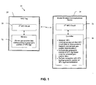
- FIG. 1 is a schematic block diagram of a near field communication (NFC) system providing NFC tag authentication based upon geographic position in accordance with an example embodiment.
- NFC near field communication
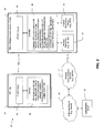
- FIG. 2 is a schematic block diagram showing the system of FIG. 1 in greater detail.
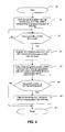
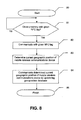
- FIGS. 3 and 4 are flow diagrams illustrating method aspects associated with the systems of FIGS. 1 and 2 .
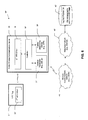
- FIG. 5 is a schematic block diagram of an NFC system in accordance with an alternative embodiment providing NFC tag geographic position determination.
- FIG. 6 is a schematic block diagram showing the system of FIG. 5 in greater detail.
- FIG. 7 is a schematic block diagram of an alternative embodiment of the system of FIG. 6 .
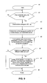
- FIGS. 8 and 9 are flow diagrams illustrating method aspects associated with the systems of FIGS. 5-7 .
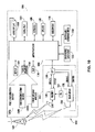
- FIG. 10 is a schematic block diagram illustrating example components of a mobile wireless communications device that may be used with the example NFC systems of FIGS. 1-2 and 5-7 .
- a near-field communication (NFC) system may include a plurality of geographically distributed NFC tags, and a tag geo-position database configured to store respective geographic positions of the NFC tags.
- the NFC system may further include a plurality of mobile wireless communications devices. Each of the mobile wireless communications devices may be configured to communicate with a given NFC tag when in proximity therewith, determine a current geographic position of the mobile wireless communications device, and communicate the determined current geographic position of the mobile wireless communications device to update the geo-position database.
- the geographic positions of the NFC tags may advantageously be provided by mobile wireless communications devices that interact with the NFC tags after deployment, which may advantageously reduce the time and expense associated with deployment of the NFC tags, as well as facilitating the addition of new NFC tags to the system or redeployment of the NFC tags to different geographical positions as necessary.
- the tag geo-position database may be configured to update the stored geographic position for the given NFC tag based upon a plurality of determined current geographic positions from different mobile wireless communications devices.
- each mobile wireless communications device may further include a position determining device, such as a global positioning system (GPS) device, for example.
- GPS global positioning system
- Each mobile wireless communications device may further include a wireless transceiver, such as a cellular transceiver, for example.
- the wireless transceiver may be configured to communicate with the tag geo-position database.
- each NFC tag may include a first NFC circuit
- each mobile wireless communications device may include a controller and a second NFC circuit coupled thereto for communicating with the first NFC circuit.
- the controller may be configured to communicate with the tag geo-position database via the first NFC circuit.
- a related communications method may include communicating between a mobile wireless communications device and a given near-field communication (NFC) tag from among a plurality of geographically distributed NFC tags when the mobile wireless communications device is in proximity to the given NFC tag.
- the method may further include determining a current geographic position of the mobile wireless communications device, and communicating the determined current geographic position of the mobile wireless communications device to update a tag geo-position database configured to store respective geographic positions of the NFC tags.
- NFC near-field communication
- a related computer-readable medium may have computer-executable instructions for causing a mobile wireless communications device to perform steps comprising communicating with a given near-field communication (NFC) tag from among a plurality of geographically distributed NFC tags when in proximity thereto, determining a current geographic position of the mobile wireless communications device, and communicating the determined current geographic position of the mobile wireless communications device to update a tag geo-position database configured to store respective geographic positions of the NFC tags.
- NFC near-field communication
- a near-field communication (NFC) system 30 illustratively includes an NFC tag 31 including a memory 32 configured to store geo-position data corresponding to a geographic position of the NFC tag (Blocks 50' and 57' of FIG. 4 ), and a first NFC sensor 33 coupled to the memory 32 and the first NFC sensor 33 being configured to initiate a transaction based upon NFC communications, as will be discussed further below.
- the geo-position data may be stored in an NFC record type definition (RTD) field in an NFC Data Exchange Format (NDEF), although other suitable formats are also possible.
- the system 30 further illustratively includes a mobile wireless communications device 34 (also referred to as a mobile device" herein) including a second NFC sensor 35 and a controller 36 coupled thereto.
- NFC is a short-range wireless communications technology in which NFC-enabled devices are “swiped,” “bumped” or otherwise moved in close proximity to communicate.
- NFC may operate at 13.56 MHz and with an effective range of about 10cm, but other suitable versions of near-field communication which may have different operating frequencies, effective ranges, etc., for example, may also be used.
- the controller 36 is configured to cause the second NFC sensor 35 to establish NFC communications with the first NFC sensor 33 when in proximity thereto and retrieve the geo-position data therefrom, at Blocks 51-52.
- the geo-position data may comprise position coordinates, such as latitude/longitude coordinates or scalar values, for example.
- the geo-position data may comprise a unique identification (ID) associated with a geographic position.
- ID unique identification
- the mobile device 34 further illustratively includes a wireless transceiver 37 and a position determining device 38 both coupled to the controller 36.
- the wireless transceiver 37 may comprise a cellular transceiver, although other suitable wireless communications formats (e.g., wireless LAN, WiMAX, etc.) may also be used.
- the position determining device 38 may comprise a global positioning system (GPS) receiver, for example, although other suitable formats such as Galileo, GLONASS, etc., may also be used.
- GPS global positioning system
- the unique ID may identify the NFC tag 31 itself (e.g., a serial number), or it may be a translated or encoded version of position coordinates. Thus, the unique ID may be used to inform the mobile device 34 where the mobile device 34 is supposed to be located, or corresponding position coordinates for the unique ID may be stored in an authentication server 40 with which the controller 36 communicates via the wireless transceiver 37, a wireless communications network 41 (e.g., a cellular network), and a wide area network (WAN) 42, such as the Internet. For example, the geographic position for the NFC tag 31 may be stored in a database at the authentication server 40 along with the unique ID.
- a wireless communications network 41 e.g., a cellular network
- WAN wide area network
- Using a unique ID to determine the appropriate position of given NFC tag may be advantageous in some implementation because of the relatively small memories provided on some NFC tags. For example, some NFC tags may have a 2 KB memory capacity or less, so using a relatively small unique ID helps to conserve the memory resources on the NFC tag for other data.
- the controller 36 is also configured to authenticate a geographic position of the NFC tag 31 based upon the retrieved geo-position data, at Block 53. This may be done in a variety of ways. For example, if the geo-position data stored in the memory 32 comprises position coordinates, then when the position coordinates are retrieved by the controller 36, the controller may then compare the retrieved position coordinates with a current geographic position provided by the position determining device 38 (Block 53' ). If the two sets of position coordinates are within a threshold distance of one another, then the position of the NFC tag 31 is authenticated.
- position coordinates of the mobile device 34 may be provided by the wireless communications network 41 (such as from cellular or WiFi access point triangulation) to the controller 36 to compare with the retrieved geographic position coordinates of the NFC tag 31.
- the authentication of the geographic position of the NFC tag 31 may be performed by the authentication server 40. That is, the controller 36 may be further configured to communicate with the authentication server 40 via the wireless transceiver 37 and wireless communications network 41 (and, if appropriate, the wide area network 42) to authenticate the geographic position of the NFC tag 31. For example, if the geo-position data stored in the memory 32 is a unique ID corresponding to geographic position coordinates for the NFC tag stored at the authentication server 40, then the authentication server may compare these coordinates with the current position of the mobile device 34 (which may be obtained from the position determining device 38, triangulation, etc.) to authenticate the geo-position data, and more particularly, the geographic position of the NFC tag 31.
- the controller 36 performs the above-noted transaction with the NFC tag 31, at Block 55, thus concluding the method illustrated in FIG. 3 (Block 56). Otherwise, the controller 36 may avoid performing or participating in the transaction with the NFC tag 31, and may also discontinue NFC communications with the NFC tag.
- the transaction may be an electronic commerce (e-commerce) transaction, such as if the NFC tag 31 is part of a ticket sales terminal, a terminal for paying fees or fares, etc.
- Other types of transactions may include opening a link in a web browser (the link being provided by the NFC tag 31, typically to view an advertisement - called a "smart poster"), pairing with a Bluetooth device to begin a Bluetooth session, reading a phone number to initiate a call or SMS, downloading a ringtone from the tag, etc.
- the NFC tag 31 may provide a clue as to the precise whereabouts of the mobile device 34 to help speed up GPS acquisition. More particularly, when a GPS receiver is missing, or has inaccurate estimates of, its position, velocity, or the current time, the receiver will then systematically search for all possible satellites to obtain this information, which significantly increases a time to first fix (TTFF) of the current location. However, providing initial estimates of one or more of these values may provide a significant reduction in the TTFF.
- TTFF time to first fix
- Authenticating the geographic position of the NFC tag 31 prior to engaging in a transaction therewith helps ensure that the NFC tag 31 is most likely in a geographic position assigned to the NFC tag 31 for security purposes, for example. That is, this authentication advantageously helps ensure that a "dummy" or otherwise unauthenticated tag is not surreptitiously set up to defraud or scam mobile device users, but is instead a valid terminal known to be deployed by a trusted source (e.g., corporation, government, etc.) at the designated location. In some embodiments, both a unique ID and position coordinates may be verified for added security. Also, this technique helps prevent a valid NFC tag from being stolen and re-located from its authorized location by a malicious party (and result in an unauthorized transaction taking place).
- a trusted source e.g., corporation, government, etc.
- an NFC system 30' illustratively includes a plurality of geographically distributed NFC tags 31', and a tag geo-position database 45' configured to store respective geographic positions of the NFC tags.
- the stored geographic positions may be latitude/longitude positions, for example.
- the NFC system 30' further illustratively includes a plurality of mobile devices 34'.
- each mobile device 34' is configured to communicate with a given NFC tag 31' when in proximity thereto, at Blocks 80-82, and determine its respective current geographic position, at Block 83. That is, upon initiating NFC communications with a respective NFC tag 31', each mobile device 34' may determine its current geographic position, for example, based upon a position determining device 38' thereof (if provided), or from a wireless communications network 41' (e.g., from triangulation), as discussed above.
- a wireless communications network 41' e.g., from triangulation
- the above-described effective communication range for NFC may be much less than the margin of error of a typical position determining device, so when the two are engaged in NFC communications their respective geographic positions may be considered to be the same.
- the location of an NFC tag 31' may only need to be recorded when the NFC tag does not yet already have a location in its memory, or it has a location but it does not match the mobile device's location (through GPS) and there is a discrepancy that needs to be corrected. That is, once the location of a given NFC tag 31' is generally known, it need not be reported endlessly.
- the determined current geographic position of a mobile device 34' may be used to update the geo-position database 45', i.e., to provide this determined geographic position as the geographic position of the given tag 31', at Block 84, thus concluding the method illustrated in FIG. 8 (Block 85).
- the geographic positions of the NFC tags 31' may advantageously be provided by mobile devices 34' that interact with the NFC tags after deployment, which may advantageously reduce the time and expense associated with deployment of the NFC tags. That is, the NFC tags 31' merely need to be positioned in the desired location, and through normal interaction with mobile devices 34' their respective geographic positions will be populated in the tag geo-position database 45'. This may also advantageously facilitate the addition of new NFC tags 31' to the system 30', or redeployment of NFC tags to different geographical positions as necessary.
- the tag geo-position database 45' may be configured to update the stored geographic position for a given NFC tag 31' based upon a plurality of determined current geographic positions from different mobile devices 34', at Blocks 86'-87'. That is, the tag geo-position database 45' may continue to refine the geographic position for a given NFC tag 31' as the tag geo-position database 45' receives new geographic position coordinates for different mobile devices 34'. For example, if an initial geographic position estimate for the given NFC tag 31' is generated through triangulation, the accuracy of this position estimate may be fairly low.
- the geo-position database 45' may advantageously be updated to reflect the more accurate coordinates. This may be done by averaging the coordinates, or replacing prior stored coordinates with new ones known to have a greater accuracy.
- mobile devices using different location technologies may report the respective location technology being used, or an expectation of its accuracy. This may add weight to reports made using more accurate techniques such as GPS, and less weight to less accurate methods like cell tower positioning, in the averaging calculation performed at the tag geo-position database 45', the stored coordinates may comprise a weighted average of several coordinates.
- the controller 36' communicates with the tag geo-position database 45' via its wireless transceiver 37'.
- the mobile device 34 and the controller 36" may instead communicate with the tag geo-position database 45" via the NFC tag 31", which further includes a WAN interface 46" for interfacing the WAN 42". That is, the mobile device 34" may communicate with the tag geo-position database 45" via the NFC tag 31'', or the NFC tag may communicate with the geo-position database directly, with the mobile device assisting by providing a precise location (such as with GPS).
- an NFC tag may have available Wi-Fi access point information stored therein along with its respective geographic location.
- the mobile device may then use a map application to indicate where the access points (or other services) are located.
- Another operation is using the geographic position of an NFC tag at a landmark to geocode information on the mobile device (e.g., geocode a picture taken in that location by swiping the mobile device with the NFC tag).
- Yet another advantageous aspect is that of associating geographic position information with contacts, etc., for reader-to-reader applications.
- contact information is exchanged between mobile devices at a particular location, such as a trade show, etc.
- the location of the exchange is recorded along with the contact, allowing all contacts obtained from that location to be searched and grouped together accordingly.
- Another approach is to use the geographic position in an NFC tag to generate calendar appointments. For example, swiping a mobile device to an NFC tag at a doctor's office may assign a calendar entry to the mobile device with location information included for a next appointment.
- Still another advantageous aspect of storing geographic position information for an NFC tag is that the NFC tag may be positioned at a location to convey direction information within a building, etc., where satellite position information is not available.
- an NFC tag with its respective geographic position information stored therein may be positioned at a gate in an airport that faces north.
- swiping the NFC tag with the mobile device allows directions to be provided based upon the direction the mobile device is facing at that particular moment (i.e., north), so that the mobile device may present a prompt requesting a user of the mobile device to go "right” or "left” depending on whether the user's next destination is a connecting flight, ground transportation, etc.
- Such information is typically more helpful inside of a building than "east" or "west” directions, for example, as the direction of east or west within a building may not be readily apparent.
- Still another application is storing multiple geographic positions on an NFC tag.
- an NFC tag at a customer service or point of sale (POS) station if a user swipes this NFC tag with a mobile device and the station in unattended or closed, directions to another station (e.g., the next closest station) are provided.
- POS point of sale
- recording the location at a POS terminal may be used to later search a sales transaction by location, for expense reporting purposes, etc.
- the device 1000 illustratively includes a housing 1200, a keyboard or keypad 1400 and an output device 1600.
- the output device shown is a display 1600, which may comprise a full graphic LCD. Other types of output devices may alternatively be utilized.
- a processing device 1800 is contained within the housing 1200 and is coupled between the keypad 1400 and the display 1600. The processing device 1800 controls the operation of the display 1600, as well as the overall operation of the mobile device 1000, in response to actuation of keys on the keypad 1400.
- the housing 1200 may be elongated vertically, or may take on other sizes and shapes (including clamshell housing structures).
- the keypad may include a mode selection key, or other hardware or software for switching between text entry and telephony entry.
- FIG. 10 In addition to the processing device 1800, other parts of the mobile device 1000 are shown schematically in FIG. 10 . These include a communications subsystem 1001; a short-range communications subsystem 1020; the keypad 1400 and the display 1600, along with other input/output devices 1060, 1080, 1100 and 1120; as well as memory devices 1160, 1180 and various other device subsystems 1201.
- the mobile device 1000 may comprise a two-way RF communications device having data and, optionally, voice communications capabilities.
- the mobile device 1000 may have the capability to communicate with other computer systems via the Internet.
- Operating system software executed by the processing device 1800 is stored in a persistent store, such as the flash memory 1160, but may be stored in other types of memory devices, such as a read only memory (ROM) or similar storage element.
- system software, specific device applications, or parts thereof may be temporarily loaded into a volatile store, such as the random access memory (RAM) 1180.
- Communications signals received by the mobile device may also be stored in the RAM 1180.
- the processing device 1800 in addition to its operating system functions, enables execution of software applications 1300A-1300N on the device 1000.
- a predetermined set of applications that control basic device operations, such as data and voice communications 1300A and 1300B, may be installed on the device 1000 during manufacture.
- a personal information manager (PIM) application may be installed during manufacture.
- the PIM may be capable of organizing and managing data items, such as e-mail, calendar events, voice mails, appointments, and task items.
- the PIM application may also be capable of sending and receiving data items via a wireless network 1401.
- the PIM data items may be seamlessly integrated, synchronized and updated via the wireless network 1401 with corresponding data items stored or associated with a host computer system.
- the communications subsystem 1001 includes a receiver 1500, a transmitter 1520, and one or more antennas 1540 and 1560.
- the communications subsystem 1001 also includes a processing module, such as a digital signal processor (DSP) 1580, and local oscillators (LOs) 1601.
- DSP digital signal processor
- LOs local oscillators
- a mobile device 1000 may include a communications subsystem 1001 designed to operate with the MobitexTM, Data TACTM or General Packet Radio Service (GPRS) mobile data communications networks, and also designed to operate with any of a variety of voice communications networks, such as AMPS, TDMA, CDMA, WCDMA, PCS, GSM, EDGE, etc. Other types of data and voice networks, both separate and integrated, may also be utilized with the mobile device 1000.
- the mobile device 1000 may also be compliant with other communications standards such as 3GSM, 3GPP, UMTS, 4G, etc.
- Network access requirements vary depending upon the type of communication system. For example, in the Mobitex and DataTAC networks, mobile devices are registered on the network using a unique personal identification number or PIN associated with each device. In GPRS networks, however, network access is associated with a subscriber or user of a device. A GPRS device therefore typically involves use of a subscriber identity module, commonly referred to as a SIM card, in order to operate on a GPRS network.
- SIM card subscriber identity module
- the mobile device 1000 may send and receive communications signals over the communication network 1401.
- Signals received from the communications network 1401 by the antenna 1540 are routed to the receiver 1500, which provides for signal amplification, frequency down conversion, filtering, channel selection, etc., and may also provide analog to digital conversion. Analog-to-digital conversion of the received signal allows the DSP 1580 to perform more complex communications functions, such as demodulation and decoding.
- signals to be transmitted to the network 1401 are processed (e.g. modulated and encoded) by the DSP 1580 and are then provided to the transmitter 1520 for digital to analog conversion, frequency up conversion, filtering, amplification and transmission to the communication network 1401 (or networks) via the antenna 1560.
- the DSP 1580 provides for control of the receiver 1500 and the transmitter 1520. For example, gains applied to communications signals in the receiver 1500 and transmitter 1520 may be adaptively controlled through automatic gain control algorithms implemented in the DSP 1580.
- a received signal such as a text message or web page download
- the communications subsystem 1001 is input to the processing device 1800.
- the received signal is then further processed by the processing device 1800 for an output to the display 1600, or alternatively to some other auxiliary I/O device 1060.
- a device may also be used to compose data items, such as e-mail messages, using the keypad 1400 and/or some other auxiliary I/O device 1060, such as a touchpad, a rocker switch, a thumb-wheel, or some other type of input device.
- the composed data items may then be transmitted over the communications network 1401 via the communications subsystem 1001.
- a voice communications mode In a voice communications mode, overall operation of the device is substantially similar to the data communications mode, except that received signals are output to a speaker 1100, and signals for transmission are generated by a microphone 1120.
- Alternative voice or audio I/O subsystems such as a voice message recording subsystem, may also be implemented on the device 1000.
- the display 1600 may also be utilized in voice communications mode, for example to display the identity of a calling party, the duration of a voice call, or other voice call related information.
- the short-range communications subsystem enables communication between the mobile device 1000 and other proximate systems or devices, which need not necessarily be similar devices.
- the short-range communications subsystem may include an infrared device and associated circuits and components, a BluetoothTM communications module to provide for communication with similarly-enabled systems and devices, or a near field communications (NFC) sensor for communicating with a NFC device or NFC tag via NFC communications.
- NFC near field communications
Landscapes
- Engineering & Computer Science (AREA)
- Computer Networks & Wireless Communication (AREA)
- Signal Processing (AREA)
- Radar, Positioning & Navigation (AREA)
- Remote Sensing (AREA)
- Physics & Mathematics (AREA)
- General Physics & Mathematics (AREA)
- Mobile Radio Communication Systems (AREA)
- Telephone Function (AREA)
Priority Applications (2)
| Application Number | Priority Date | Filing Date | Title |
|---|---|---|---|
| EP10187603.5A EP2442128B1 (fr) | 2010-10-14 | 2010-10-14 | Système de communication de champ proche (nfc) doté de dispositifs de communication sans fil déterminant les positions géographiques et procédés apparentés |
| CA2755065A CA2755065C (fr) | 2010-10-14 | 2011-10-13 | Systeme de communication en champ proche avec dispositifs de communication sans fil mobiles pour determiner les positions geographiques des etiquettes nfc et procedes connexes |
Applications Claiming Priority (1)
| Application Number | Priority Date | Filing Date | Title |
|---|---|---|---|
| EP10187603.5A EP2442128B1 (fr) | 2010-10-14 | 2010-10-14 | Système de communication de champ proche (nfc) doté de dispositifs de communication sans fil déterminant les positions géographiques et procédés apparentés |
Publications (3)
| Publication Number | Publication Date |
|---|---|
| EP2442128A1 EP2442128A1 (fr) | 2012-04-18 |
| EP2442128A9 true EP2442128A9 (fr) | 2012-12-26 |
| EP2442128B1 EP2442128B1 (fr) | 2016-05-11 |
Family
ID=43825383
Family Applications (1)
| Application Number | Title | Priority Date | Filing Date |
|---|---|---|---|
| EP10187603.5A Active EP2442128B1 (fr) | 2010-10-14 | 2010-10-14 | Système de communication de champ proche (nfc) doté de dispositifs de communication sans fil déterminant les positions géographiques et procédés apparentés |
Country Status (2)
| Country | Link |
|---|---|
| EP (1) | EP2442128B1 (fr) |
| CA (1) | CA2755065C (fr) |
Cited By (1)
| Publication number | Priority date | Publication date | Assignee | Title |
|---|---|---|---|---|
| DK201500097A1 (da) * | 2015-02-18 | 2016-09-05 | Mobisoft Aps | System og fremgangsmåde til identifikation og lokalisering af fysiske enheder |
Families Citing this family (1)
| Publication number | Priority date | Publication date | Assignee | Title |
|---|---|---|---|---|
| JP5759034B1 (ja) * | 2014-02-10 | 2015-08-05 | 株式会社ぐるなび | 認証処理システム |
Family Cites Families (3)
| Publication number | Priority date | Publication date | Assignee | Title |
|---|---|---|---|---|
| US8107446B2 (en) * | 2005-11-07 | 2012-01-31 | Radiofy Llc | Wireless RFID networking systems and methods |
| WO2007079232A2 (fr) * | 2005-12-30 | 2007-07-12 | Pango Networks, Inc. | Procedes et appareil destines a la synthese d’emplacement dans un environnement de reseau sans fil |
| CN101685504A (zh) * | 2008-09-26 | 2010-03-31 | 深圳富泰宏精密工业有限公司 | Rfid信号接收系统及方法 |
-
2010
- 2010-10-14 EP EP10187603.5A patent/EP2442128B1/fr active Active
-
2011
- 2011-10-13 CA CA2755065A patent/CA2755065C/fr active Active
Cited By (1)
| Publication number | Priority date | Publication date | Assignee | Title |
|---|---|---|---|---|
| DK201500097A1 (da) * | 2015-02-18 | 2016-09-05 | Mobisoft Aps | System og fremgangsmåde til identifikation og lokalisering af fysiske enheder |
Also Published As
| Publication number | Publication date |
|---|---|
| CA2755065A1 (fr) | 2012-04-14 |
| CA2755065C (fr) | 2014-12-09 |
| EP2442128B1 (fr) | 2016-05-11 |
| EP2442128A1 (fr) | 2012-04-18 |
Similar Documents
| Publication | Publication Date | Title |
|---|---|---|
| CA2814407C (fr) | Systeme de communication en champ proche (nfc) offrant une authentification de position geographique d'etiquette nfc, et procedes associes | |
| US8750793B2 (en) | Near-field communication (NFC) system with mobile wireless communications devices determining geographic positions of NFC tags and related methods | |
| US20120094596A1 (en) | Near-field communication (nfc) system providing nfc tag geographic position authentication and related methods | |
| US8750795B2 (en) | Mobile wireless communications device having a near field communication (NFC) device and providing memory disabling and related methods | |
| US12282913B2 (en) | Mobile wireless communications device having digital wallet with multi-mode user card and related methods | |
| EP2584769B1 (fr) | Dispositif de communication mobile fournissant des caractéristiques de compatibilité d'applet NFC et procédés associés | |
| US8326281B2 (en) | Mobile wireless communications device providing object reference data based upon near field communication (NFC) and related methods | |
| US20230124410A1 (en) | Communication system with digital wallet having blank user card and related methods | |
| US20150046258A1 (en) | Communications system providing mobile device advertisments based upon activity history and related methods | |
| CN102967869A (zh) | 用于确定移动设备位置的方法和设备 | |
| US20100330903A1 (en) | Method and device for the transmission of data between communicating mobile terminals | |
| CA2755065C (fr) | Systeme de communication en champ proche avec dispositifs de communication sans fil mobiles pour determiner les positions geographiques des etiquettes nfc et procedes connexes | |
| US20120208456A1 (en) | Mobile wireless communications device providing object reference data based upon near field communication (nfc) and related methods | |
| CA2831158C (fr) | Dispositif mobile de communications sans fil possedant un dispositif nfc (communication en champ proche) et permettant une desactivation de memoire, et procedes associes | |
| EP2814231B1 (fr) | Dispositif de communications sans fil mobile ayant un portefeuille numérique avec carte utilisateur multimode et procédés associés | |
| CA2768166C (fr) | Dispositif de communication sans fil fournissant des donnees de renvoi a des objets reposant sur des communications en champ proche et procedes connexes | |
| EP3451264A1 (fr) | Système de communication à portefeuille numérique ayant une carte vierge utilisateur et procédés associés | |
| HK1176198A (en) | Mobile wireless communications device having a near field communication (nfc) device and providing memory disabling and related methods |
Legal Events
| Date | Code | Title | Description |
|---|---|---|---|
| PUAI | Public reference made under article 153(3) epc to a published international application that has entered the european phase |
Free format text: ORIGINAL CODE: 0009012 |
|
| 17P | Request for examination filed |
Effective date: 20101014 |
|
| AK | Designated contracting states |
Kind code of ref document: A1 Designated state(s): AL AT BE BG CH CY CZ DE DK EE ES FI FR GB GR HR HU IE IS IT LI LT LU LV MC MK MT NL NO PL PT RO RS SE SI SK SM TR |
|
| AX | Request for extension of the european patent |
Extension state: BA ME |
|
| 17Q | First examination report despatched |
Effective date: 20130408 |
|
| RAP1 | Party data changed (applicant data changed or rights of an application transferred) |
Owner name: BLACKBERRY LIMITED |
|
| RAP1 | Party data changed (applicant data changed or rights of an application transferred) |
Owner name: BLACKBERRY LIMITED |
|
| GRAP | Despatch of communication of intention to grant a patent |
Free format text: ORIGINAL CODE: EPIDOSNIGR1 |
|
| INTG | Intention to grant announced |
Effective date: 20151204 |
|
| GRAS | Grant fee paid |
Free format text: ORIGINAL CODE: EPIDOSNIGR3 |
|
| GRAA | (expected) grant |
Free format text: ORIGINAL CODE: 0009210 |
|
| AK | Designated contracting states |
Kind code of ref document: B1 Designated state(s): AL AT BE BG CH CY CZ DE DK EE ES FI FR GB GR HR HU IE IS IT LI LT LU LV MC MK MT NL NO PL PT RO RS SE SI SK SM TR |
|
| REG | Reference to a national code |
Ref country code: GB Ref legal event code: FG4D |
|
| REG | Reference to a national code |
Ref country code: CH Ref legal event code: EP |
|
| REG | Reference to a national code |
Ref country code: AT Ref legal event code: REF Ref document number: 799070 Country of ref document: AT Kind code of ref document: T Effective date: 20160515 |
|
| REG | Reference to a national code |
Ref country code: IE Ref legal event code: FG4D |
|
| REG | Reference to a national code |
Ref country code: DE Ref legal event code: R096 Ref document number: 602010033227 Country of ref document: DE |
|
| REG | Reference to a national code |
Ref country code: LT Ref legal event code: MG4D |
|
| REG | Reference to a national code |
Ref country code: NL Ref legal event code: MP Effective date: 20160511 |
|
| REG | Reference to a national code |
Ref country code: FR Ref legal event code: PLFP Year of fee payment: 7 |
|
| PG25 | Lapsed in a contracting state [announced via postgrant information from national office to epo] |
Ref country code: LT Free format text: LAPSE BECAUSE OF FAILURE TO SUBMIT A TRANSLATION OF THE DESCRIPTION OR TO PAY THE FEE WITHIN THE PRESCRIBED TIME-LIMIT Effective date: 20160511 Ref country code: FI Free format text: LAPSE BECAUSE OF FAILURE TO SUBMIT A TRANSLATION OF THE DESCRIPTION OR TO PAY THE FEE WITHIN THE PRESCRIBED TIME-LIMIT Effective date: 20160511 Ref country code: NL Free format text: LAPSE BECAUSE OF FAILURE TO SUBMIT A TRANSLATION OF THE DESCRIPTION OR TO PAY THE FEE WITHIN THE PRESCRIBED TIME-LIMIT Effective date: 20160511 Ref country code: NO Free format text: LAPSE BECAUSE OF FAILURE TO SUBMIT A TRANSLATION OF THE DESCRIPTION OR TO PAY THE FEE WITHIN THE PRESCRIBED TIME-LIMIT Effective date: 20160811 |
|
| REG | Reference to a national code |
Ref country code: AT Ref legal event code: MK05 Ref document number: 799070 Country of ref document: AT Kind code of ref document: T Effective date: 20160511 |
|
| PG25 | Lapsed in a contracting state [announced via postgrant information from national office to epo] |
Ref country code: ES Free format text: LAPSE BECAUSE OF FAILURE TO SUBMIT A TRANSLATION OF THE DESCRIPTION OR TO PAY THE FEE WITHIN THE PRESCRIBED TIME-LIMIT Effective date: 20160511 Ref country code: RS Free format text: LAPSE BECAUSE OF FAILURE TO SUBMIT A TRANSLATION OF THE DESCRIPTION OR TO PAY THE FEE WITHIN THE PRESCRIBED TIME-LIMIT Effective date: 20160511 Ref country code: LV Free format text: LAPSE BECAUSE OF FAILURE TO SUBMIT A TRANSLATION OF THE DESCRIPTION OR TO PAY THE FEE WITHIN THE PRESCRIBED TIME-LIMIT Effective date: 20160511 Ref country code: SE Free format text: LAPSE BECAUSE OF FAILURE TO SUBMIT A TRANSLATION OF THE DESCRIPTION OR TO PAY THE FEE WITHIN THE PRESCRIBED TIME-LIMIT Effective date: 20160511 Ref country code: GR Free format text: LAPSE BECAUSE OF FAILURE TO SUBMIT A TRANSLATION OF THE DESCRIPTION OR TO PAY THE FEE WITHIN THE PRESCRIBED TIME-LIMIT Effective date: 20160812 Ref country code: HR Free format text: LAPSE BECAUSE OF FAILURE TO SUBMIT A TRANSLATION OF THE DESCRIPTION OR TO PAY THE FEE WITHIN THE PRESCRIBED TIME-LIMIT Effective date: 20160511 Ref country code: PT Free format text: LAPSE BECAUSE OF FAILURE TO SUBMIT A TRANSLATION OF THE DESCRIPTION OR TO PAY THE FEE WITHIN THE PRESCRIBED TIME-LIMIT Effective date: 20160912 |
|
| PG25 | Lapsed in a contracting state [announced via postgrant information from national office to epo] |
Ref country code: IT Free format text: LAPSE BECAUSE OF FAILURE TO SUBMIT A TRANSLATION OF THE DESCRIPTION OR TO PAY THE FEE WITHIN THE PRESCRIBED TIME-LIMIT Effective date: 20160511 |
|
| PG25 | Lapsed in a contracting state [announced via postgrant information from national office to epo] |
Ref country code: DK Free format text: LAPSE BECAUSE OF FAILURE TO SUBMIT A TRANSLATION OF THE DESCRIPTION OR TO PAY THE FEE WITHIN THE PRESCRIBED TIME-LIMIT Effective date: 20160511 Ref country code: EE Free format text: LAPSE BECAUSE OF FAILURE TO SUBMIT A TRANSLATION OF THE DESCRIPTION OR TO PAY THE FEE WITHIN THE PRESCRIBED TIME-LIMIT Effective date: 20160511 Ref country code: SK Free format text: LAPSE BECAUSE OF FAILURE TO SUBMIT A TRANSLATION OF THE DESCRIPTION OR TO PAY THE FEE WITHIN THE PRESCRIBED TIME-LIMIT Effective date: 20160511 Ref country code: CZ Free format text: LAPSE BECAUSE OF FAILURE TO SUBMIT A TRANSLATION OF THE DESCRIPTION OR TO PAY THE FEE WITHIN THE PRESCRIBED TIME-LIMIT Effective date: 20160511 Ref country code: RO Free format text: LAPSE BECAUSE OF FAILURE TO SUBMIT A TRANSLATION OF THE DESCRIPTION OR TO PAY THE FEE WITHIN THE PRESCRIBED TIME-LIMIT Effective date: 20160511 |
|
| REG | Reference to a national code |
Ref country code: DE Ref legal event code: R097 Ref document number: 602010033227 Country of ref document: DE |
|
| PG25 | Lapsed in a contracting state [announced via postgrant information from national office to epo] |
Ref country code: SM Free format text: LAPSE BECAUSE OF FAILURE TO SUBMIT A TRANSLATION OF THE DESCRIPTION OR TO PAY THE FEE WITHIN THE PRESCRIBED TIME-LIMIT Effective date: 20160511 Ref country code: BE Free format text: LAPSE BECAUSE OF FAILURE TO SUBMIT A TRANSLATION OF THE DESCRIPTION OR TO PAY THE FEE WITHIN THE PRESCRIBED TIME-LIMIT Effective date: 20160511 Ref country code: AT Free format text: LAPSE BECAUSE OF FAILURE TO SUBMIT A TRANSLATION OF THE DESCRIPTION OR TO PAY THE FEE WITHIN THE PRESCRIBED TIME-LIMIT Effective date: 20160511 Ref country code: PL Free format text: LAPSE BECAUSE OF FAILURE TO SUBMIT A TRANSLATION OF THE DESCRIPTION OR TO PAY THE FEE WITHIN THE PRESCRIBED TIME-LIMIT Effective date: 20160511 |
|
| PLBE | No opposition filed within time limit |
Free format text: ORIGINAL CODE: 0009261 |
|
| STAA | Information on the status of an ep patent application or granted ep patent |
Free format text: STATUS: NO OPPOSITION FILED WITHIN TIME LIMIT |
|
| 26N | No opposition filed |
Effective date: 20170214 |
|
| PG25 | Lapsed in a contracting state [announced via postgrant information from national office to epo] |
Ref country code: SI Free format text: LAPSE BECAUSE OF FAILURE TO SUBMIT A TRANSLATION OF THE DESCRIPTION OR TO PAY THE FEE WITHIN THE PRESCRIBED TIME-LIMIT Effective date: 20160511 |
|
| REG | Reference to a national code |
Ref country code: CH Ref legal event code: PL |
|
| PG25 | Lapsed in a contracting state [announced via postgrant information from national office to epo] |
Ref country code: MC Free format text: LAPSE BECAUSE OF FAILURE TO SUBMIT A TRANSLATION OF THE DESCRIPTION OR TO PAY THE FEE WITHIN THE PRESCRIBED TIME-LIMIT Effective date: 20160511 |
|
| REG | Reference to a national code |
Ref country code: IE Ref legal event code: MM4A |
|
| PG25 | Lapsed in a contracting state [announced via postgrant information from national office to epo] |
Ref country code: CH Free format text: LAPSE BECAUSE OF NON-PAYMENT OF DUE FEES Effective date: 20161031 Ref country code: LI Free format text: LAPSE BECAUSE OF NON-PAYMENT OF DUE FEES Effective date: 20161031 |
|
| PG25 | Lapsed in a contracting state [announced via postgrant information from national office to epo] |
Ref country code: LU Free format text: LAPSE BECAUSE OF NON-PAYMENT OF DUE FEES Effective date: 20161014 |
|
| REG | Reference to a national code |
Ref country code: FR Ref legal event code: PLFP Year of fee payment: 8 |
|
| PG25 | Lapsed in a contracting state [announced via postgrant information from national office to epo] |
Ref country code: IE Free format text: LAPSE BECAUSE OF NON-PAYMENT OF DUE FEES Effective date: 20161014 |
|
| PG25 | Lapsed in a contracting state [announced via postgrant information from national office to epo] |
Ref country code: HU Free format text: LAPSE BECAUSE OF FAILURE TO SUBMIT A TRANSLATION OF THE DESCRIPTION OR TO PAY THE FEE WITHIN THE PRESCRIBED TIME-LIMIT; INVALID AB INITIO Effective date: 20101014 Ref country code: CY Free format text: LAPSE BECAUSE OF FAILURE TO SUBMIT A TRANSLATION OF THE DESCRIPTION OR TO PAY THE FEE WITHIN THE PRESCRIBED TIME-LIMIT Effective date: 20160511 |
|
| PG25 | Lapsed in a contracting state [announced via postgrant information from national office to epo] |
Ref country code: MT Free format text: LAPSE BECAUSE OF NON-PAYMENT OF DUE FEES Effective date: 20161031 Ref country code: TR Free format text: LAPSE BECAUSE OF FAILURE TO SUBMIT A TRANSLATION OF THE DESCRIPTION OR TO PAY THE FEE WITHIN THE PRESCRIBED TIME-LIMIT Effective date: 20160511 Ref country code: IS Free format text: LAPSE BECAUSE OF FAILURE TO SUBMIT A TRANSLATION OF THE DESCRIPTION OR TO PAY THE FEE WITHIN THE PRESCRIBED TIME-LIMIT Effective date: 20160511 Ref country code: MK Free format text: LAPSE BECAUSE OF FAILURE TO SUBMIT A TRANSLATION OF THE DESCRIPTION OR TO PAY THE FEE WITHIN THE PRESCRIBED TIME-LIMIT Effective date: 20160511 |
|
| PG25 | Lapsed in a contracting state [announced via postgrant information from national office to epo] |
Ref country code: BG Free format text: LAPSE BECAUSE OF FAILURE TO SUBMIT A TRANSLATION OF THE DESCRIPTION OR TO PAY THE FEE WITHIN THE PRESCRIBED TIME-LIMIT Effective date: 20160511 |
|
| REG | Reference to a national code |
Ref country code: FR Ref legal event code: PLFP Year of fee payment: 9 |
|
| PG25 | Lapsed in a contracting state [announced via postgrant information from national office to epo] |
Ref country code: AL Free format text: LAPSE BECAUSE OF FAILURE TO SUBMIT A TRANSLATION OF THE DESCRIPTION OR TO PAY THE FEE WITHIN THE PRESCRIBED TIME-LIMIT Effective date: 20160511 |
|
| REG | Reference to a national code |
Ref country code: DE Ref legal event code: R082 Ref document number: 602010033227 Country of ref document: DE Ref country code: DE Ref legal event code: R081 Ref document number: 602010033227 Country of ref document: DE Owner name: MALIKIE INNOVATIONS LTD., IE Free format text: FORMER OWNER: BLACKBERRY LIMITED, WATERLOO, ONTARIO, CA |
|
| PGFP | Annual fee paid to national office [announced via postgrant information from national office to epo] |
Ref country code: DE Payment date: 20251028 Year of fee payment: 16 |
|
| PGFP | Annual fee paid to national office [announced via postgrant information from national office to epo] |
Ref country code: GB Payment date: 20251023 Year of fee payment: 16 |
|
| PGFP | Annual fee paid to national office [announced via postgrant information from national office to epo] |
Ref country code: FR Payment date: 20251027 Year of fee payment: 16 |