EP2442275A2 - Verfahren und Vorrichtung zur dreidimensionalen Bildrekonstruktion - Google Patents
Verfahren und Vorrichtung zur dreidimensionalen Bildrekonstruktion Download PDFInfo
- Publication number
- EP2442275A2 EP2442275A2 EP11174618A EP11174618A EP2442275A2 EP 2442275 A2 EP2442275 A2 EP 2442275A2 EP 11174618 A EP11174618 A EP 11174618A EP 11174618 A EP11174618 A EP 11174618A EP 2442275 A2 EP2442275 A2 EP 2442275A2
- Authority
- EP
- European Patent Office
- Prior art keywords
- camera
- horizon
- scene
- image
- sin
- Prior art date
- Legal status (The legal status is an assumption and is not a legal conclusion. Google has not performed a legal analysis and makes no representation as to the accuracy of the status listed.)
- Withdrawn
Links
Images






Classifications
-
- G—PHYSICS
- G06—COMPUTING OR CALCULATING; COUNTING
- G06T—IMAGE DATA PROCESSING OR GENERATION, IN GENERAL
- G06T7/00—Image analysis
- G06T7/50—Depth or shape recovery
- G06T7/536—Depth or shape recovery from perspective effects, e.g. by using vanishing points
-
- G—PHYSICS
- G06—COMPUTING OR CALCULATING; COUNTING
- G06T—IMAGE DATA PROCESSING OR GENERATION, IN GENERAL
- G06T2207/00—Indexing scheme for image analysis or image enhancement
- G06T2207/10—Image acquisition modality
- G06T2207/10016—Video; Image sequence
-
- G—PHYSICS
- G06—COMPUTING OR CALCULATING; COUNTING
- G06T—IMAGE DATA PROCESSING OR GENERATION, IN GENERAL
- G06T2207/00—Indexing scheme for image analysis or image enhancement
- G06T2207/10—Image acquisition modality
- G06T2207/10032—Satellite or aerial image; Remote sensing
-
- G—PHYSICS
- G06—COMPUTING OR CALCULATING; COUNTING
- G06T—IMAGE DATA PROCESSING OR GENERATION, IN GENERAL
- G06T2207/00—Indexing scheme for image analysis or image enhancement
- G06T2207/10—Image acquisition modality
- G06T2207/10048—Infrared image
-
- G—PHYSICS
- G06—COMPUTING OR CALCULATING; COUNTING
- G06T—IMAGE DATA PROCESSING OR GENERATION, IN GENERAL
- G06T2207/00—Indexing scheme for image analysis or image enhancement
- G06T2207/30—Subject of image; Context of image processing
- G06T2207/30232—Surveillance
Definitions
- the present invention relates to a method for constructing a three-dimensional model of a scene captured as a video stream, a method for mounting two cameras on an aerial vehicle and a computer-implemented method for determining a distance from a camera mounted to an aerial vehicle.
- the invention relates generally to the field of image processing and, more specifically, to a method and apparatus for three-dimensional image reconstruction and processing.
- One way that three dimensional computer models of a scene can be created is from photographs.
- This method uses stereo triangulation to measure the distance to various points in the images.
- the baseline for this triangulation can be produced by two widely separated cameras, or by one camera with relative motion between the camera and the subject.
- a second method uses perspective geometry to reconstruct the scene in three dimensions if there are strong perspective lines in the image. For example, renaissance paintings, with well defined perspective lines, have been used to create three dimensional computer models of the scene in the painting. This is done by mapping the perspective lines which converge to their vanishing points and interpolating the material in between the perspective lines.
- Converting a painting, or a photograph, into a three dimensional model of the represented scene is usually done by using the information inherent in perspective lines to define the geometry of the scene.
- Renaissance painters often showed receding intersections of walls, panels, floor tiles and roof or ceiling structures. These receding elements converged to well defined vanishing points according to the then newly discovered rules of perspective geometry. In recent times these rules of perspective geometry have been worked backward to develop three dimensional models of some of these Renaissance paintings.
- a camera i.e. camera pose
- a method for constructing a three-dimensional model of a scene captured as a video stream comprising: obtaining a video stream of a scene by a first camera; locating a horizon with respect to the scene with a second camera; and in a processor in communication with a memory having instructions stored therein which, when executed, constructing a three-dimensional model of the scene based upon the obtained video stream and the located horizon.
- the second camera includes an infrared sensor that is configured to penetrate haze and other obscurants.
- the method further comprises: co-mounting the first and the second camera on a common support structure.
- the second camera is configured to image an area outside of a field of view of the first camera.
- the method further comprises: finding a range to an object within the scene by measuring an image position of the object with respect to the located horizon.
- the method further comprises: determining a vanishing point in a nadir direction.
- the method further comprises: correlating a vertical edge within the scene with a motion derived nadir vanishing point to refine an estimated camera pose.
- the vanishing point in the nadir direction is determined based on a downward tilt angle of the first camera and a roll angle about a line of sight of the first camera.
- the method further comprises: measuring slopes, locations and divergences of vertical edges within the video stream of the scene to determine the downward tilt angle of the first camera, the roll angle about the line of sight of the first camera, and the scene horizon.
- the method further comprises: determining a distance to an object within the scene on a ground plane at a known relative altitude based on a focal length of the first camera and the scene horizon, the downward tilt angle of the first camera, and the roll angle about a line of sight of the first camera.
- the method further comprises: determining different range features of other objects within the scene based on the determined distance to the object.
- the method further comprises: determining a physical height of the object based on a height of the image of the object and the downward tilt angle of the first camera.
- a method for mounting two cameras on an aerial vehicle comprising: arranging a first camera to maintain an essentially horizontal orientation with respect to a horizon to determine a line of the horizon; and arranging a second camera relative to the first camera to image an object at ground level.
- the method further comprises: mounting the second camera in a mounting assembly, wherein the mounting assembly is configured to allow the second camera to move in at least one degree of freedom relative to the first camera.
- the at least one degree of freedom comprises movement about a depression angle with regard to a pivot point of the mounting assembly, or movement about a vertical axis of the second camera, or both.
- both the first and the second camera are arranged together in the mounting assembly.
- the first camera includes an infrared camera.
- the horizon line is outside a field of view of the camera.
- a method for constructing a three-dimensional model of a scene captured as a video stream.
- the method includes obtaining a video stream of a scene by a first camera; locating a horizon with respect to the scene with a second camera; and in a processor in communication with a memory having instructions stored therein which, when executed, constructing a three-dimensional model of the scene based upon the obtained video stream and the located horizon.
- a method for mounting two cameras on an aerial vehicle.
- the method includes arranging a first camera to maintain an essentially horizontal orientation with respect to a horizon to determine a line of the horizon; and arranging a second camera relative to the first camera to image an object at ground level.
- a computer-implemented method for determining a distance from a camera mounted to an aerial vehicle and locations within an image captured by the camera.
- the method can use a processor in communication with a memory having instructions stored therein which, when executed, perform the method including determining a location of a horizon with respect to a center of the camera, wherein the camera includes a lens with a focal length, the camera arranged at a height above a ground plane and a tilt angle with respect to the horizon; determining a horizon line based on the determined location of the horizon; determining a tilt of the horizon line; determining a location of a ground point in the image; and determining, by a distance determining computer, the distance from the height of the camera, the focal length of the lens of the camera, the tilt angle and the location of the ground point in the image.
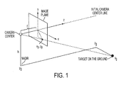
- Figure 1 shows a conventional geometry for image formation including a camera coordinate system (left handed) at a standard starting position.
- the camera has a focal length, f .
- the reference location, or origin, of the image is in the center of image at the point where the camera centerline passes through the image plane. Points on the ground are referenced to this camera center. In other words, for this case, the World Coordinate locations of points on the ground are not of concern.
- the camera is viewing a target below on the ground from some altitude, h .
- the target's coordinates (with respect to the unrotated camera center) are x g , y g , z g .
- the ray that extends from the camera center to the ground target intercepts the image plane at x p , y p .
- equations (1) can be extended by rotating the camera.
- the camera is assumed not to be rotated about the camera center line. That is, the camera does not roll around its center line axis. This assumption renders the x-axis to always be parallel to the horizon. This constraint will later be relaxed.
- the rationale for this assumption is that the camera can be mounted in a vehicle (e.g. an aircraft) which travels in a straight line and therefore does not significantly pitch up and down.
- the camera may rotate about its line-of-sight axis. This severe case may require image (roll) derotation.
- the derotation could be determined by looking for obvious vertical lines in the image, or by estimating the horizon angle if the horizon is visible. It is also assumed that, once the camera has been rotated, its orientation remains fixed with respect to the straight line flight path. The camera may be mounted in a gimbal, but once the gimbal angles have been specified, these angles remain constant for the duration of the measurement.
- Equations (11) and (12) can be used to get the camera pose for a camera which is moving in a straight line at constant altitude. Moreover, Equations (11) and (12) can also be used to determine the camera pose for non-uniform motion.
- a first method is to have the motion be along the z-axis.
- z g is allowed to go to infinity in equations (11) and (12).
- movement is made parallel to the x-axis.
- x g is allowed to go to infinity in equations (11) and (12).
- the principal vanishing point is along the direction of motion. This is defined as the epipole, or principal vanishing point, between two successive camera positions.
- Equations (15) and (16) tell us that x p goes to infinity if x g goes to infinity and ⁇ is not zero.
- x g is allowed to go to infinity in equations (11) and (12). This is equivalent to moving in the x -direction (positively or negatively). This involves a different orientation of the camera with respect to the direction of travel.
- Equation (18) is the same as (14), this means the horizon angle is always the same, independent of the azimuth orientation, ⁇ , of the camera. Again, once the down angle, ⁇ , has been determined, then the camera relative azimuth angle, ⁇ , can be determined from (17).
- Equation (19) show that x p goes to infinity when x g goes to infinity.
- nadir vanishing points As for the nadir vanishing points, let y g is extend to minus infinity ( h is infinity) in equations (11) and (12). This gives the vanishing point, x ey , y ey , in the nadir direction.
- the nadir vanishing point can be useful in urban scenes because building usually have vertical edges. Thus, by correlating these building edges with the motion derived nadir vanishing point, the estimated camera pose can be refined.
- y p is finite if ⁇ is not equal to zero. This is because the camera's y -axis is tilted down so that y p tracks the increase of altitude, h .
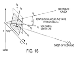
- the horizon line is governed by only two parameters, the downward tilt (or dip) angle, ⁇ , of the camera and the roll angle, ⁇ , about the camera's line of sight. These angles also determine the location of the nadir point. It often is the case that either the horizon or the nadir, or both, will lie outside the image frame. In which case, some indirect means can be used to determine these angles.
- cities can provide an indirect means for estimating the ⁇ and ⁇ orientation angles of the camera since buildings usually have vertical edges.
- the images of these edges are typically sloped in such a way that the edges of multiple buildings will converge to a nadir point.
- the (virtual) angle of the horizon (or the nadir direction) tells us the dip angle, ⁇ , of the camera.
- the vertical edge of a building will not, in general, appear to be vertical in most images. This is because a perspective rendering of the scene causes vertical edges to converge to a nadir vanishing point. Usually, but not always, this nadir point will lie somewhere below the bottom of the image.
- ⁇ the slope of the vertical edge of a building by: ⁇ ⁇ ⁇ y ⁇ x
- a variable, ( D ) is defined as a stand-in for the denominators in (23) and (24): D ⁇ h sin ⁇ + z g cos ⁇
- Equation (29) tells us dip angle, ⁇ , of the camera below the horizontal. Equations (28) and (29) are derived by a alternative method below.
- the distance to any object on a (ground) plane at a known relative altitude, h can be determined to an acceptable approximation.
- the camera focal length, f needs to be determined.
- the ranges to different features can be determined from a single image. Thus, triangulation using more than one image is not needed.
- the accuracy of the range measurement will be a function of the accuracy of our knowledge of ⁇ , ⁇ and h.
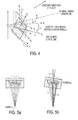
- the geometry is illustrated by Figure 6 .
- the objective is to measure the ground range, R , from immediately below the camera out to the target object, and the slant range, ⁇ , from the camera to the target object. To do this, both z g and x g need to be determined.
- the camera is assumed to dip an angle, ⁇ , below horizontal. It is also assume that the camera roll angle, ⁇ , has been corrected, during the image processing, so that the (virtual) horizon line is now horizontal.
- z g can be calculated first using equation (37), then this value can be inserted into (39) to calculate x g .
- equations (40) and (37) are both linearly dependent on the relative altitude, h .
- h becomes a universal scale factor for reconstructing the three dimensional relationships of the objects within the scene.
- both D and the relative orientations, ⁇ , of the camera at the ends of D can be determined.
- the two ground objects act as a stereo baseline for inverse triangulation of the camera locations and orientations.
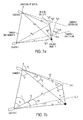
- Figure 7 shows the distances angles used by the algorithm and is a plan view of the ground beneath the camera (the camera being at two positions denoted by camera 1 and camera 2).
- Each local coordinate system is such that the local z -axis is on the ground and is aligned with the camera centerline.
- the camera's focal length, downward tilt angle, ⁇ , and altitude above the ground plane, h does not change as we move from the first position to the second.
- the camera may rotate in relative azimuth, ⁇ .
- the temporarily fixed parameters are allowed to vary, so long as the new parameter values are known.
- the distances, R 11 , R 12 , from the first camera position to the two ground plane objects are measured. Also, the distances R 21 , R 22 , from the second camera position to the same two ground objects are measured. These measurements require a knowledge of the camera's down tilt angle, ⁇ , and a correction for any camera rotation, ⁇ , around the camera centerline.
- equation (37), from above, and equations (39) and (41) are used to determine the distances R 11 , R 12 , R 21 , R 22 based on the pixel locations, x p and y p of the objects in the image:
- angles ⁇ 12 , ⁇ 21 and ⁇ 22 can be determined.
- a 2 R 11 2 + R 12 2 - 2 R 11 ⁇ R 12 ⁇ cos ⁇ 1
- a 2 R 21 2 + R 22 2 - 2 R 21 ⁇ R 22 ⁇ cos ⁇ 2
- a standard trigonometric relationship for triangles can also be used to find the following angles:
- an averaged value or a noise weighted average value can be used that may be more accurate than either value by itself.
- Figure 7 shows a fundamental asymmetry in that for the first camera position the angle ⁇ 1 involves a rotation towards the triangle complex.
- the angle ⁇ 2 denotes a rotation away from the triangle complex.
- a "radial vector field” is here defined as an ensemble of isolated vectors, or line segments, which diverge from, or converge to, a common point.
- radial vector fields can be extracted from images.
- a typical urban scene has many features which form fields of vectors which point to scene vanishing points. These might be the edges of buildings, or roadways, or arrays of windows, etc.
- the displacements of various objects in the scene also form a radial field of vectors.
- the vectors represent the vertical edges of buildings, these edges all extend to the nadir vanishing point.
- the nadir vanishing point is known, it is easy to find the horizon, even if the horizon is outside the field of view of the camera. With knowledge of the horizon, and the height of the camera above the ground plane, the distance to any point on the ground plane can be calculated.
- a grid of roads yields edges which extend to vanishing points on the horizon.
- the horizon vanishing points from building base lines and roof lines can be found. These horizon vanishing points provide an alternative method for defining the horizon.
- a field of difference vectors which extend to the motion induced vanishing points of the two images.
- Knowledge of these vanishing points provides a mechanism for determining camera pose (i.e. camera orientation). Once the camera pose has been discovered, it is possible to determine the three dimensional structure of the scene.
- a Least Squares technique can be used to find these vanishing points from radial vector fields.
- radial vector fields A number of different image phenomena produce vector fields that radiate from a single point.
- radial vector fields Each of these radial vector fields have an appearance which is typically represented by Figure 9 .
- a single image or a pair of images may have several such vector fields - each converging towards a different vanishing point.
- these radial vector fields may define both the natural geometry of the scene and the motion of the camera, as shown by Figure 10 .
- the various parameters which control the structures of these various radial vector fields are discussed. That is, the apparent locations of the vanishing points of each of these vector fields is determined. From these vanishing points, information about the structure of the scene can be gained.
- the axes of the coordinate system are labeled according to regular image convention ( up is to the right in this illustration).
- the point of convergence (the vanishing point) is displaced from the y-axis through an angle, ⁇ .
- the location of this point is x 0 , y 0 (in the original image coordinate system). It is assumed that the convergence of the vector field is governed by an angle, ⁇ , which is related to the camera's orientation.
- equation (69) always yields zero for each contributing vector. That is, all the contributing vectors point to the location x 0 , y 0 . In reality, though, there will be imperfections in the measurements so these vectors will not all point to the true x 0 , y 0 . However, if a least squares technique is used, then a good estimate of x 0 , y 0 can be determined. By using the entire field of vectors to estimate, x 0 , y 0 , more of such vectors can be used to improve the estimate. Furthermore, it does not matter where in the image these vectors are located, or how long they are (unless they are weighted by length), they will all contribute equally to the final estimate.
- E ⁇ i A i + S i y 0 - x 0 2
- a i ⁇ x i - S i y i for each vector in a particular vector field. The summation is over all these vectors.
- n - ⁇ i S i ⁇ i S i - ⁇ i S i 2 - 1 1 Det ⁇ - ⁇ i S i 2 ⁇ i S i - ⁇ i S i n
- Equations (80) and (81) provide the coordinates of the vanishing point, and therefore the essential description, of the (vertically oriented) vector field. It is recognized that the computation burden grows only linearly with the number of vectors in the field.
- equations (90) and (93) represent ensembles of points that lie close to straight lines which are defined by the parameters, y A , x A , for the vertical representation and, x a , y a , for the horizontal representation.
- the characteristic lines have slopes y A and x a , respectively.
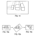
- the methodology outlined above would intermingle the linearized vector plots, as in Figures 13a, 13b and 13c , so that the vector fields would be impossible to disentangle.
- the vector fields can be separated by taking advantage of the fact that the vector fields are at right angles. For example, the whole image, and not just the individual vectors, can be rotated by 45°, as is shown in Figure 15 .
- the slopes of the vector fields do not have singularities and both fields can be described by the same formulas, such as equations (70) through (81), or, (82) through (59), but not both.
- the Least Squares fitted control lines for the vector fields will be at right angles in a plot such as that of Figures 13a, 13b and 13c ,.
- a method that uses observation of the horizon to derive key information needed to reconstruct a three dimensional model of the scene is disclosed.
- This method can be used with many types of cameras (and camera combinations) and many types of mounting platforms.
- One application of this method is in aerial survey - particularly aerial survey using a small Unmanned Aerial Vehicle (UAV).
- UAV Unmanned Aerial Vehicle
- the payload capacity is often too small to accommodate a stable platform for the camera(s) and a high accuracy Inertial Navigation System (INS) to measure the position and pointing direction of the camera.
- INS Inertial Navigation System
- observation of the horizon provides the additional information needed for three dimensional reconstruction.
- Knowledge of the horizon may also be used to correct drift in the low quality Inertial Measurement Units (IMU's) which are becoming common even in very small (micro) UAV's.
- IMU's Inertial Measurement Units
- a process is disclosed using a set of equations which give the distance from the camera to any point in the scene, provided that certain conditions are met, such as the location of the horizon with respect to the camera center be known.
- the horizon line need not lie within the field of view of the camera; however, the tilt of the horizon line and the altitude of the camera above the local ground must be known if the resulting distance measurements are to be calibrated. If the altitude is not known, then it is still possible to reconstruct an unscaled model of the scene. Such unscaled modeling works best in a flat ground urban environment where the geometric relationships among the buildings are particularly simple. In some aspects, general scene reconstruction the availability of a terrain model is normally required.
- GPS Global Positioning System
- x g and z g are the coordinates of a point in the ground plane.
- the parameter, h is the height of the camera above the ground plane.
- x p and y p define the location of the ground point in the image.
- x p corresponds to x g and y p corresponds to z g .
- the coordinate system used by the image, and these equations, has its origin in the center of the image. It is assumed that the image has been corrected for pincushion or barrel distortion so that it is rectilinear.
- the rotation around the center line should be corrected so that the x -axis of the image is aligned with the horizon. For example, this can be done by appropriate measurement of the horizon line.
- the entire image can be rotated so that the image horizon is parallel to the true horizon. This can be done using various computational algorithms as would be apparent.
- the ⁇ rotation angle is kept track of in all the subsequent calculations, such that the effect of the camera ⁇ rotation can be analytically removed. This can also be done using various computational algorithms as would be apparent.
- Equation (98) shows that the estimated cross range ground position, x g , of an object does depend on the y p position of that object in the image.
- Equation (98) is easily modified, accordingly.
- a separate camera such as an infrared camera
- this separate camera can be an uncooled bolometer infrared camera, which is best suited to be the horizon camera.
- Such a camera can operate out to wavelengths on the order of 12 microns, which will typically penetrate through all but clouds and therefore is likely to provide a horizon image under most condition.
- Other suitable cameras can be used.
- the regular imaging camera can produce the information needed to make a scaled model of the scene it is imaging. This aspect is useful for photography from an aerial platform. Such a platform would normally fly above obstructions which obscure the horizon.
- An infrared horizon measuring camera can be selected to penetrate haze. Imaging in the infrared makes it more likely that the horizon will be seen under most environmental conditions.
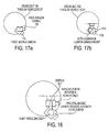
- wide field of view horizon camera 1705 can be mounted in a piggy-back relationship with principal imaging camera 1710.
- principal imaging camera 1710 it is assumed that the two cameras are fixed fastened together in such a way that they move together.
- the coupled pair of cameras can be fix-mounted to the body of the vehicle, or the combination can be mounted in a gimbals set.
- wide field of view horizon camera 1715 and principal imaging camera 1720 can be mounted in a gimbals set 1725.
- horizon camera 1715 can be mounted on the aircraft so that it is pointing essentially horizontally.
- Principal imaging camera 1720 can be mounted in gimbals in such a way that its depression angle can change with time and the camera can also rotate around a vertical axis.
- Horizon camera 1715 can be mounted on the outer gimbals in such a way that it pivots around a vertical axis together with principal imaging camera 1720 so that both cameras are pointed towards a common azimuth direction.
- horizon camera 1715 does not tilt down together with principal imaging camera 1720, but stays pointed towards the horizon, regardless of the depression angle of principal imaging camera 1720.
- An angle transfer mechanism such as a shaft angle encoder, measures the relative angle between the two cameras so that the location of the horizon line can be compared (analytically) with the image in the principal imaging camera, as shown in Figure 18 .
- the lenses of most cameras produce some kind of distortion, such as pincushion or barrel distortion, this distortion can be corrected to more accurately measure and model the scene.
- Such correction can be done digitally, through remapping the digital images. This will require a spatial calibration procedure either before, or after, the images have been taken.
- the horizon camera should have a wide enough field of view that it can successfully capture a substantial region of the horizon, regardless of any roll, pitch or yaw of the vehicle during the image capture period.
- a computer-implemented method for deriving vanishing points, and major perspective lines, for a scene.
- This method relies on extracting a multitude of local vectors from the scene. This multitude defines a vector field (or even multiple, overlapping, vector fields) relating to the perspective geometry. Information about the location of the vanishing points is determined using this vector field approach because it relies on information drawn automatically from all over the image, rather than just from a few selected lines.
- This method uses the understanding about how information in an image is organized. For example, many images may be decomposed into small elemental vectors which converge to a vanishing point and which can be defined as a field of vectors.
- vanishing points which are associated with these fields may be located anywhere with respect to the depicted scene. They may even lie well outside the frame of the image. For example, if the image depicts a scene generally looking towards a horizon, then the nadir or zenith vanishing points will assuredly lie well outside the image. Many images of rectilinear buildings have their edges converging to vanishing points on the horizon which may, or may not lie within the frame of the image. The method is capable of locating these vanishing points regardless of whether, or not, these vanishing points lie within the frame of the image.
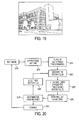
- Figure 19 shown an illustrative image, where the building in this image has particularly strong perspective information.
- the vertical vanishing point is at the zenith because we are looking generally up at the building rather than down.
- each of the vanishing points are at the convergences of multiple lines in the image.
- all three vanishing points lie outside the frame of the image.
- there are multiple vanishing points there are a corresponding number of types of image features - in this case, three. Each of these types of features form a vector field.
- These fields of features are primarily composed of vectors which define the directions of the edges in the image. In many areas these vector fields overlap. For example, the vertical feature vector fields overlap with the horizontal feature vector fields. Another characteristic of these vector fields is that they appear to radiate from their corresponding vanishing points. This apparent radiation is an inherent property of the mathematics of perspective geometry which describes the scene.
- a scene such as that illustrated by Figure 19
- a scene is analyzed to extract the edge vectors from the scene, sort these edge vectors into distinguishable radial fields of vectors and then find the vanishing points that correspond to each of the fields of vectors. From the relative image locations of these vanishing points, information about the three dimensional characteristics of the scene can be derived.
- Figure 20 shows a process flow in accordance with various aspects of the present disclosure.
- each new image will undergo feature extraction and analysis.
- the first analytical stage of this process is to extract, at 2010, vectors which represent the linear edge features in the image (as many edge features as possible).
- Such linear features might be the vertical edges of buildings, windows, etc. Or, they might be horizontal features such as the tops and bottoms of windows, roof lines, base lines of buildings, street curbs or side walks, etc.
- the Sobel operator is one such.
- the Canny edge detector is another.
- Figures 21 a and 21 b show the first stage in the extraction of these edge vectors.
- the next stage is to perform a Radial Vector Field transformation, at 2015, of these vectors.
- This transformation is to convert each edge vector into a single point in the transform space, such that the transformed points from all the edge vectors in a given vector field line up in such a way as to define the image vanishing point for that particular vector field. If there are multiple vanishing points, then there will be a corresponding multiple number of lines in the transform space.
- the parameters of each of these lines is extracted at 2030, for example by using the LSF method at 2025.
- the line parameters are converted into the coordinates of the corresponding vanishing point in the original image space.
- Typical lines radiating from these computed vanishing points are shown in Figures 25a and 25b .
- the lines in Figures 25a and 25b were computed from the peak values along the ridges in Figures 23, 24a and 24b .
- the process is iterated at 2040 until each line cloud has been separated, line fitted and converted into a corresponding vanishing point. When all the vanishing points have been extracted, the analysis of this particular image is finished, at 2045, and another image may then be selected for analysis.
- FIG. 26 is a block diagram illustrating an example computing device 2600 that is arranged to perform the various processes and/or methods in accordance with the various aspects of the present disclosure.
- computing device 2600 typically includes one or more processors 2610 and a system memory 2620.
- a memory bus 2630 may be used for communicating between processor 2610 and system memory 2620.
- processor 2610 may be of any type including but not limited to a microprocessor ( ⁇ P), a microcontroller ( ⁇ C), a digital signal processor (DSP), or any combination thereof.
- Processor 2610 may include one more levels of caching, such as a level one cache 2611 and a level two cache 2612, a processor core 2613, and registers 2614.
- An example processor core 2613 may include an arithmetic logic unit (ALU), a floating point unit (FPU), a digital signal processing core (DSP Core), or any combination thereof.
- An example memory controller 2615 may also be used with processor 2610, or in some implementations memory controller 2615 may be an internal part of processor 2610.
- system memory 2620 may be of any type including but not limited to volatile memory (such as RAM), non-volatile memory (such as ROM, flash memory, etc.) or any combination thereof
- System memory 2620 may include an operating system 2621, one or more applications 2622, and program data 2624.
- Application 2622 may include one or more of the various algorithms, processes or methods discussed above 2623 that is arranged to perform the functions as described with respect to processes of Figures 1-25 .
- Program data 2624 may include data 2625 that may be useful for one or more of the various algorithms, methods or processes as is described herein.
- application 2622 may be arranged to operate with program data 2624 on operating system 2621 such that implementations of the various algorithms, processes or methods may be provided as described herein.
- This described basic configuration 2601 is illustrated in Figure 26 by those components within the inner dashed line.
- Computing device 2600 may have additional features or functionality, and additional interfaces to facilitate communications between basic configuration 2601 and any required devices and interfaces.
- a bus/interface controller 2642 may be used to facilitate communications between basic configuration 2601 and one or more data storage devices 2650 via a storage interface bus 2641.
- Data storage devices 2650 may be removable storage devices 2651, non-removable storage devices 2652, or a combination thereof Examples of removable storage and non-removable storage devices include magnetic disk devices such as flexible disk drives and hard-disk drives (HDD), optical disk drives such as compact disk (CD) drives or digital versatile disk (DVD) drives, solid state drives (SSD), and tape drives to name a few.
- Example computer storage media may include volatile and nonvolatile, removable and non-removable media implemented in any method or technology for storage of information, such as computer readable instructions, data structures, program modules, or other data.
- Computer storage media includes, but is not limited to, RAM, ROM, EEPROM, flash memory or other memory technology, CD-ROM, digital versatile disks (DVD) or other optical storage, magnetic cassettes, magnetic tape, magnetic disk storage or other magnetic storage devices, or any other medium which may be used to store the desired information and which may be accessed by computing device 2600. Any such computer storage media may be part of computing device 2600.
- Computing device 2600 may also include an interface bus 2642 for facilitating communication from various interface devices (e.g., output devices 2660, peripheral interfaces 2670, and communication devices 2680) to basic configuration 2601 via bus/interface controller 2642.
- Example output devices 2660 include a graphics processing unit 2661 and an audio processing unit 2662, which may be configured to communicate to various external devices such as a display or speakers via one or more A/V ports 2663.
- Example peripheral interfaces 2670 include a serial interface controller 2671 or a parallel interface controller 2672, which may be configured to communicate with external devices such as input devices (e.g., keyboard, mouse, pen, voice input device, touch input device, etc.) or other peripheral devices (e.g., printer, scanner, etc.) via one or more I/O ports 2673.
- An example communication device 2680 includes a network controller 2681, which may be arranged to facilitate communications with one or more other computing devices 2690 over a network communication link via one or more communication ports 2682.
- the network communication link may be one example of a communication media.
- Communication media may typically be embodied by computer readable instructions, data structures, program modules, or other data in a modulated data signal, such as a carrier wave or other transport mechanism, and may include any information delivery media.
- a "modulated data signal" may be a signal that has one or more of its characteristics set or changed in such a manner as to encode information in the signal.
- communication media may include wired media such as a wired network or direct-wired connection, and wireless media such as acoustic, radio frequency (RF), microwave, infrared (IR) and other wireless media.
- RF radio frequency
- IR infrared
- the term computer readable media as used herein may include both physical storage media and communication media.
- Computing device 2600 may be implemented as a portion of a small-form factor portable (or mobile) electronic device such as a cell phone, a personal data assistant (PDA), a personal media player device, a wireless web-watch device, a personal headset device, an application specific device, or a hybrid device that include any of the above functions.
- a small-form factor portable (or mobile) electronic device such as a cell phone, a personal data assistant (PDA), a personal media player device, a wireless web-watch device, a personal headset device, an application specific device, or a hybrid device that include any of the above functions.
- PDA personal data assistant
- Computing device 2600 may also be implemented as a personal computer including both laptop computer and non-laptop computer configurations.
Landscapes
- Engineering & Computer Science (AREA)
- Computer Vision & Pattern Recognition (AREA)
- Physics & Mathematics (AREA)
- General Physics & Mathematics (AREA)
- Theoretical Computer Science (AREA)
- Image Analysis (AREA)
- Length Measuring Devices By Optical Means (AREA)
- Image Processing (AREA)
Applications Claiming Priority (1)
| Application Number | Priority Date | Filing Date | Title |
|---|---|---|---|
| US12/888,166 US8610708B2 (en) | 2010-09-22 | 2010-09-22 | Method and apparatus for three-dimensional image reconstruction |
Publications (2)
| Publication Number | Publication Date |
|---|---|
| EP2442275A2 true EP2442275A2 (de) | 2012-04-18 |
| EP2442275A3 EP2442275A3 (de) | 2012-04-25 |
Family
ID=44508825
Family Applications (1)
| Application Number | Title | Priority Date | Filing Date |
|---|---|---|---|
| EP11174618A Withdrawn EP2442275A3 (de) | 2010-09-22 | 2011-07-20 | Verfahren und Vorrichtung zur dreidimensionalen Bildrekonstruktion |
Country Status (3)
| Country | Link |
|---|---|
| US (1) | US8610708B2 (de) |
| EP (1) | EP2442275A3 (de) |
| IL (1) | IL214151A (de) |
Cited By (2)
| Publication number | Priority date | Publication date | Assignee | Title |
|---|---|---|---|---|
| WO2015160287A1 (en) * | 2014-04-14 | 2015-10-22 | Saab Vricon Systems Ab | A method and system for estimating information related to a vehicle pitch and/or roll angle |
| US9767615B2 (en) | 2014-04-23 | 2017-09-19 | Raytheon Company | Systems and methods for context based information delivery using augmented reality |
Families Citing this family (44)
| Publication number | Priority date | Publication date | Assignee | Title |
|---|---|---|---|---|
| WO2011155161A1 (ja) * | 2010-06-11 | 2011-12-15 | パナソニック株式会社 | 画像処理装置および画像処理方法 |
| US8848970B2 (en) | 2011-04-26 | 2014-09-30 | Digimarc Corporation | Salient point-based arrangements |
| WO2013086475A1 (en) * | 2011-12-08 | 2013-06-13 | Cornell University | System and methods for world-scale camera pose estimation |
| US8886449B2 (en) * | 2012-01-13 | 2014-11-11 | Qualcomm Incorporated | Calibrated hardware sensors for estimating real-world distances |
| US9019350B2 (en) * | 2012-04-12 | 2015-04-28 | Raytheon Company | Stereo rectification method |
| US9147122B2 (en) | 2012-05-31 | 2015-09-29 | Qualcomm Incorporated | Pose estimation based on peripheral information |
| US9135705B2 (en) * | 2012-10-16 | 2015-09-15 | Qualcomm Incorporated | Sensor calibration and position estimation based on vanishing point determination |
| US20150071488A1 (en) * | 2013-09-11 | 2015-03-12 | Sony Corporation | Imaging system with vanishing point detection using camera metadata and method of operation thereof |
| US9967546B2 (en) | 2013-10-29 | 2018-05-08 | Vefxi Corporation | Method and apparatus for converting 2D-images and videos to 3D for consumer, commercial and professional applications |
| US20150116458A1 (en) | 2013-10-30 | 2015-04-30 | Barkatech Consulting, LLC | Method and apparatus for generating enhanced 3d-effects for real-time and offline appplications |
| KR101368325B1 (ko) * | 2013-12-10 | 2014-02-28 | 한국지질자원연구원 | 항공 탐사용 적외선 카메라의 렌즈 손상 방지용 커버를 구비하는 항공 탐사용 항공기 |
| US9311639B2 (en) | 2014-02-11 | 2016-04-12 | Digimarc Corporation | Methods, apparatus and arrangements for device to device communication |
| US10158847B2 (en) | 2014-06-19 | 2018-12-18 | Vefxi Corporation | Real—time stereo 3D and autostereoscopic 3D video and image editing |
| US20150379759A1 (en) * | 2014-06-30 | 2015-12-31 | Jagonal Pty Ltd | System and method for rendering buildings in three dimensions |
| US20180167586A1 (en) * | 2014-11-18 | 2018-06-14 | Elwha Llc | Satellite imaging system with edge processing |
| US9536320B1 (en) * | 2014-12-23 | 2017-01-03 | John H. Prince | Multiple coordinated detectors for examination and ranging |
| US9836814B2 (en) * | 2015-01-09 | 2017-12-05 | Panasonic Intellectual Property Management Co., Ltd. | Display control apparatus and method for stepwise deforming of presentation image radially by increasing display ratio |
| NO343441B1 (en) * | 2015-02-20 | 2019-03-11 | FLIR Unmanned Aerial Systems AS | Depth measurement system |
| US9854155B1 (en) | 2015-06-16 | 2017-12-26 | Amazon Technologies, Inc. | Determining camera auto-focus settings |
| US9826156B1 (en) * | 2015-06-16 | 2017-11-21 | Amazon Technologies, Inc. | Determining camera auto-focus settings |
| US10360718B2 (en) * | 2015-08-14 | 2019-07-23 | Samsung Electronics Co., Ltd. | Method and apparatus for constructing three dimensional model of object |
| US10148932B2 (en) | 2015-11-13 | 2018-12-04 | Vefxi Corporation | 3D system including object separation |
| WO2017083509A1 (en) * | 2015-11-13 | 2017-05-18 | Craig Peterson | Three dimensional system |
| US10277877B2 (en) | 2015-11-13 | 2019-04-30 | Vefxi Corporation | 3D system including a neural network |
| US10148933B2 (en) | 2015-11-13 | 2018-12-04 | Vefxi Corporation | 3D system including rendering with shifted compensation |
| US10242448B2 (en) | 2015-11-13 | 2019-03-26 | Vefxi Corporation | 3D system including queue management |
| US10277879B2 (en) | 2015-11-13 | 2019-04-30 | Vefxi Corporation | 3D system including rendering with eye displacement |
| US10225542B2 (en) | 2015-11-13 | 2019-03-05 | Vefxi Corporation | 3D system including rendering with angular compensation |
| US10121280B2 (en) | 2015-11-13 | 2018-11-06 | Vefxi Corporation | 3D system including rendering with three dimensional transformation |
| US10122987B2 (en) | 2015-11-13 | 2018-11-06 | Vefxi Corporation | 3D system including additional 2D to 3D conversion |
| US10277880B2 (en) | 2015-11-13 | 2019-04-30 | Vefxi Corporation | 3D system including rendering with variable displacement |
| US10284837B2 (en) | 2015-11-13 | 2019-05-07 | Vefxi Corporation | 3D system including lens modeling |
| CN105574928A (zh) * | 2015-12-11 | 2016-05-11 | 深圳易嘉恩科技有限公司 | 一种行车图像处理方法和第一电子设备 |
| FR3046229A1 (fr) * | 2015-12-29 | 2017-06-30 | Thales Sa | Procede de representation graphique d'une vue synthetique tridimensionnelle du paysage exterieur dans un systeme de visualisation de bord pour aeronef |
| US10154244B2 (en) | 2016-02-18 | 2018-12-11 | Vefxi Corporation | 3D system including a marker mode |
| US10586404B1 (en) * | 2016-12-07 | 2020-03-10 | Lytx, Inc. | Load imbalance factor estimation |
| WO2018105117A1 (ja) * | 2016-12-09 | 2018-06-14 | 三菱電機ビルテクノサービス株式会社 | 工事写真管理システム |
| US10460465B2 (en) | 2017-08-31 | 2019-10-29 | Hover Inc. | Method for generating roof outlines from lateral images |
| CN108871353B (zh) * | 2018-07-02 | 2021-10-15 | 上海西井信息科技有限公司 | 路网地图生成方法、系统、设备及存储介质 |
| CN111311742B (zh) * | 2020-03-27 | 2023-05-05 | 阿波罗智能技术(北京)有限公司 | 三维重建方法、三维重建装置和电子设备 |
| US11847739B2 (en) | 2020-08-26 | 2023-12-19 | Hover Inc. | Systems and methods for pitch determination |
| CN112530010B (zh) * | 2020-12-07 | 2024-06-28 | 阳光新能源开发股份有限公司 | 数据获取方法和系统 |
| US11980132B2 (en) * | 2021-08-18 | 2024-05-14 | Firefly Automatix, Inc. | Determining orientation of a mower using horizon mapping |
| CN115130593B (zh) * | 2022-06-30 | 2025-08-19 | 腾讯科技(深圳)有限公司 | 连接关系的确定方法、装置、设备及介质 |
Family Cites Families (3)
| Publication number | Priority date | Publication date | Assignee | Title |
|---|---|---|---|---|
| US20090110267A1 (en) | 2007-09-21 | 2009-04-30 | The Regents Of The University Of California | Automated texture mapping system for 3D models |
| US8073190B2 (en) * | 2007-11-16 | 2011-12-06 | Sportvision, Inc. | 3D textured objects for virtual viewpoint animations |
| US8350850B2 (en) * | 2008-03-31 | 2013-01-08 | Microsoft Corporation | Using photo collections for three dimensional modeling |
-
2010
- 2010-09-22 US US12/888,166 patent/US8610708B2/en active Active
-
2011
- 2011-07-18 IL IL214151A patent/IL214151A/en active IP Right Grant
- 2011-07-20 EP EP11174618A patent/EP2442275A3/de not_active Withdrawn
Non-Patent Citations (1)
| Title |
|---|
| None |
Cited By (3)
| Publication number | Priority date | Publication date | Assignee | Title |
|---|---|---|---|---|
| WO2015160287A1 (en) * | 2014-04-14 | 2015-10-22 | Saab Vricon Systems Ab | A method and system for estimating information related to a vehicle pitch and/or roll angle |
| US9285460B2 (en) | 2014-04-14 | 2016-03-15 | Saab Vricon Systems Ab | Method and system for estimating information related to a vehicle pitch and/or roll angle |
| US9767615B2 (en) | 2014-04-23 | 2017-09-19 | Raytheon Company | Systems and methods for context based information delivery using augmented reality |
Also Published As
| Publication number | Publication date |
|---|---|
| IL214151A (en) | 2015-01-29 |
| US8610708B2 (en) | 2013-12-17 |
| EP2442275A3 (de) | 2012-04-25 |
| US20120069019A1 (en) | 2012-03-22 |
| IL214151A0 (en) | 2011-11-30 |
Similar Documents
| Publication | Publication Date | Title |
|---|---|---|
| US8610708B2 (en) | Method and apparatus for three-dimensional image reconstruction | |
| Alsadik et al. | The simultaneous localization and mapping (SLAM): An overview | |
| Wu et al. | Integration of aerial oblique imagery and terrestrial imagery for optimized 3D modeling in urban areas | |
| CN102741706B (zh) | 地理参照图像区域的方法 | |
| US9171225B2 (en) | Device, method, and recording medium for detecting and removing mistracked points in visual odometry systems | |
| US9998660B2 (en) | Method of panoramic 3D mosaicing of a scene | |
| US20090154793A1 (en) | Digital photogrammetric method and apparatus using intergrated modeling of different types of sensors | |
| CN107917699B (zh) | 一种用于提高山区地貌倾斜摄影测量空三质量的方法 | |
| Ramezani et al. | Omnidirectional visual-inertial odometry using multi-state constraint Kalman filter | |
| CN117330052A (zh) | 基于红外视觉、毫米波雷达和imu融合的定位与建图方法及系统 | |
| Khoshelham et al. | Vehicle positioning in the absence of GNSS signals: Potential of visual-inertial odometry | |
| Xian et al. | Fusing stereo camera and low-cost inertial measurement unit for autonomous navigation in a tightly-coupled approach | |
| Abeho et al. | Effects of camera calibration on the accuracy of Unmanned Aerial Vehicle sensor products | |
| Zhou et al. | Automatic orthorectification and mosaicking of oblique images from a zoom lens aerial camera | |
| Lee et al. | Georegistration of airborne hyperspectral image data | |
| Hussnain et al. | Enhanced trajectory estimation of mobile laser scanners using aerial images | |
| CN106371096B (zh) | 机载双天线InSAR三维构像模型构建方法 | |
| Briskin et al. | Estimating pose and motion using bundle adjustment and digital elevation model constraints | |
| Kupervasser et al. | Robust positioning of drones for land use monitoring in strong terrain relief using vision-based navigation | |
| CN109003295B (zh) | 一种无人机航空影像快速匹配方法 | |
| Mirisola et al. | Trajectory recovery and 3d mapping from rotation-compensated imagery for an airship | |
| Xu | Mapping and localization for extraterrestrial robotic explorations | |
| Meguro et al. | Omni-directional Motion Stereo Vision based on Accurate GPS/INS Navigation System | |
| Liu et al. | Absolute orientation and localization estimation from an omnidirectional image | |
| CN119399086B (zh) | 一种轻小型无人机推扫影像扭曲变形校正方法 |
Legal Events
| Date | Code | Title | Description |
|---|---|---|---|
| PUAL | Search report despatched |
Free format text: ORIGINAL CODE: 0009013 |
|
| PUAI | Public reference made under article 153(3) epc to a published international application that has entered the european phase |
Free format text: ORIGINAL CODE: 0009012 |
|
| AK | Designated contracting states |
Kind code of ref document: A2 Designated state(s): AL AT BE BG CH CY CZ DE DK EE ES FI FR GB GR HR HU IE IS IT LI LT LU LV MC MK MT NL NO PL PT RO RS SE SI SK SM TR |
|
| AX | Request for extension of the european patent |
Extension state: BA ME |
|
| AK | Designated contracting states |
Kind code of ref document: A3 Designated state(s): AL AT BE BG CH CY CZ DE DK EE ES FI FR GB GR HR HU IE IS IT LI LT LU LV MC MK MT NL NO PL PT RO RS SE SI SK SM TR |
|
| AX | Request for extension of the european patent |
Extension state: BA ME |
|
| RIC1 | Information provided on ipc code assigned before grant |
Ipc: G06T 7/00 20060101AFI20120319BHEP |
|
| 17P | Request for examination filed |
Effective date: 20121024 |
|
| STAA | Information on the status of an ep patent application or granted ep patent |
Free format text: STATUS: THE APPLICATION HAS BEEN WITHDRAWN |
|
| 18W | Application withdrawn |
Effective date: 20140626 |