EP2442277A2 - Appareil d'aide au diagnostic, programme d'aide au diagnostic et procédé d'aide au diagnostic - Google Patents
Appareil d'aide au diagnostic, programme d'aide au diagnostic et procédé d'aide au diagnostic Download PDFInfo
- Publication number
- EP2442277A2 EP2442277A2 EP11184725A EP11184725A EP2442277A2 EP 2442277 A2 EP2442277 A2 EP 2442277A2 EP 11184725 A EP11184725 A EP 11184725A EP 11184725 A EP11184725 A EP 11184725A EP 2442277 A2 EP2442277 A2 EP 2442277A2
- Authority
- EP
- European Patent Office
- Prior art keywords
- index value
- image
- dimensional
- heart
- representing
- Prior art date
- Legal status (The legal status is an assumption and is not a legal conclusion. Google has not performed a legal analysis and makes no representation as to the accuracy of the status listed.)
- Withdrawn
Links
Images



Classifications
-
- G—PHYSICS
- G06—COMPUTING OR CALCULATING; COUNTING
- G06T—IMAGE DATA PROCESSING OR GENERATION, IN GENERAL
- G06T7/00—Image analysis
- G06T7/20—Analysis of motion
-
- G—PHYSICS
- G06—COMPUTING OR CALCULATING; COUNTING
- G06T—IMAGE DATA PROCESSING OR GENERATION, IN GENERAL
- G06T11/00—Two-dimensional [2D] image generation
- G06T11/20—Drawing from basic elements
- G06T11/26—Drawing of charts or graphs
-
- G—PHYSICS
- G06—COMPUTING OR CALCULATING; COUNTING
- G06T—IMAGE DATA PROCESSING OR GENERATION, IN GENERAL
- G06T7/00—Image analysis
- G06T7/0002—Inspection of images, e.g. flaw detection
- G06T7/0012—Biomedical image inspection
- G06T7/0014—Biomedical image inspection using an image reference approach
- G06T7/0016—Biomedical image inspection using an image reference approach involving temporal comparison
-
- A—HUMAN NECESSITIES
- A61—MEDICAL OR VETERINARY SCIENCE; HYGIENE
- A61B—DIAGNOSIS; SURGERY; IDENTIFICATION
- A61B6/00—Apparatus or devices for radiation diagnosis; Apparatus or devices for radiation diagnosis combined with radiation therapy equipment
- A61B6/50—Apparatus or devices for radiation diagnosis; Apparatus or devices for radiation diagnosis combined with radiation therapy equipment specially adapted for specific body parts; specially adapted for specific clinical applications
- A61B6/503—Apparatus or devices for radiation diagnosis; Apparatus or devices for radiation diagnosis combined with radiation therapy equipment specially adapted for specific body parts; specially adapted for specific clinical applications for diagnosis of the heart
-
- A—HUMAN NECESSITIES
- A61—MEDICAL OR VETERINARY SCIENCE; HYGIENE
- A61B—DIAGNOSIS; SURGERY; IDENTIFICATION
- A61B6/00—Apparatus or devices for radiation diagnosis; Apparatus or devices for radiation diagnosis combined with radiation therapy equipment
- A61B6/52—Devices using data or image processing specially adapted for radiation diagnosis
- A61B6/5211—Devices using data or image processing specially adapted for radiation diagnosis involving processing of medical diagnostic data
- A61B6/5217—Devices using data or image processing specially adapted for radiation diagnosis involving processing of medical diagnostic data extracting a diagnostic or physiological parameter from medical diagnostic data
-
- A—HUMAN NECESSITIES
- A61—MEDICAL OR VETERINARY SCIENCE; HYGIENE
- A61B—DIAGNOSIS; SURGERY; IDENTIFICATION
- A61B6/00—Apparatus or devices for radiation diagnosis; Apparatus or devices for radiation diagnosis combined with radiation therapy equipment
- A61B6/52—Devices using data or image processing specially adapted for radiation diagnosis
- A61B6/5211—Devices using data or image processing specially adapted for radiation diagnosis involving processing of medical diagnostic data
- A61B6/5229—Devices using data or image processing specially adapted for radiation diagnosis involving processing of medical diagnostic data combining image data of a patient, e.g. combining a functional image with an anatomical image
- A61B6/5235—Devices using data or image processing specially adapted for radiation diagnosis involving processing of medical diagnostic data combining image data of a patient, e.g. combining a functional image with an anatomical image combining images from the same or different ionising radiation imaging techniques, e.g. PET and CT
-
- G—PHYSICS
- G01—MEASURING; TESTING
- G01R—MEASURING ELECTRIC VARIABLES; MEASURING MAGNETIC VARIABLES
- G01R33/00—Arrangements or instruments for measuring magnetic variables
- G01R33/20—Arrangements or instruments for measuring magnetic variables involving magnetic resonance
- G01R33/44—Arrangements or instruments for measuring magnetic variables involving magnetic resonance using nuclear magnetic resonance [NMR]
- G01R33/48—NMR imaging systems
- G01R33/4808—Multimodal MR, e.g. MR combined with positron emission tomography [PET], MR combined with ultrasound or MR combined with computed tomography [CT]
- G01R33/481—MR combined with positron emission tomography [PET] or single photon emission computed tomography [SPECT]
-
- G—PHYSICS
- G01—MEASURING; TESTING
- G01R—MEASURING ELECTRIC VARIABLES; MEASURING MAGNETIC VARIABLES
- G01R33/00—Arrangements or instruments for measuring magnetic variables
- G01R33/20—Arrangements or instruments for measuring magnetic variables involving magnetic resonance
- G01R33/44—Arrangements or instruments for measuring magnetic variables involving magnetic resonance using nuclear magnetic resonance [NMR]
- G01R33/48—NMR imaging systems
- G01R33/54—Signal processing systems, e.g. using pulse sequences ; Generation or control of pulse sequences; Operator console
- G01R33/56—Image enhancement or correction, e.g. subtraction or averaging techniques, e.g. improvement of signal-to-noise ratio and resolution
- G01R33/5608—Data processing and visualization specially adapted for MR, e.g. for feature analysis and pattern recognition on the basis of measured MR data, segmentation of measured MR data, edge contour detection on the basis of measured MR data, for enhancing measured MR data in terms of signal-to-noise ratio by means of noise filtering or apodization, for enhancing measured MR data in terms of resolution by means for deblurring, windowing, zero filling, or generation of gray-scaled images, colour-coded images or images displaying vectors instead of pixels
-
- G—PHYSICS
- G06—COMPUTING OR CALCULATING; COUNTING
- G06T—IMAGE DATA PROCESSING OR GENERATION, IN GENERAL
- G06T2200/00—Indexing scheme for image data processing or generation, in general
- G06T2200/24—Indexing scheme for image data processing or generation, in general involving graphical user interfaces [GUIs]
-
- G—PHYSICS
- G06—COMPUTING OR CALCULATING; COUNTING
- G06T—IMAGE DATA PROCESSING OR GENERATION, IN GENERAL
- G06T2207/00—Indexing scheme for image analysis or image enhancement
- G06T2207/10—Image acquisition modality
- G06T2207/10072—Tomographic images
-
- G—PHYSICS
- G06—COMPUTING OR CALCULATING; COUNTING
- G06T—IMAGE DATA PROCESSING OR GENERATION, IN GENERAL
- G06T2207/00—Indexing scheme for image analysis or image enhancement
- G06T2207/20—Special algorithmic details
- G06T2207/20212—Image combination
- G06T2207/20221—Image fusion; Image merging
-
- G—PHYSICS
- G06—COMPUTING OR CALCULATING; COUNTING
- G06T—IMAGE DATA PROCESSING OR GENERATION, IN GENERAL
- G06T2207/00—Indexing scheme for image analysis or image enhancement
- G06T2207/30—Subject of image; Context of image processing
- G06T2207/30004—Biomedical image processing
- G06T2207/30048—Heart; Cardiac
Definitions
- the present invention relates to an apparatus, method, and computer program for assisting diagnosis by displaying cardiac motion in a two-dimensional image representing cardiac function calculated from three-dimensional image data.
- an apparatus that analyzes a state or motion of an organ of a subject based on three-dimensional data obtained by imaging the subject and displays analysis results on a screen in a manner appropriate for diagnosis.
- the function to analyze cardiac beat motion a function that calculates evaluation values of cardiac function (myocardial wall motion, wall thickness variation, and the like) based on time series three-dimensional data is known.
- a plurality of cross-sections perpendicular to an axis passing through the cardiac base (where a blood vessel is connected on the upper side of a heart) and the cardiac apex (pointed portion on the lower side) is set and these evaluation values are calculated for each cross-section.
- the calculated evaluation values are displayed three-dimensionally according to cardiac shape.
- a bull's eye image in which evaluation values of each cross-section are disposed on the circumferences of concentric circles having different radii is known.
- Japanese Unexamined Patent Publication No. 2002-306483 discloses a method that extracts information of a contour of an organ from each of a plurality of cross-sectional images with respect to a plurality of phases, calculates a three-dimensional contour of the organ from the information of the plurality of extracted contours, calculates information of motion of the three-dimensional contour based on a travel distance between corresponding apexes on the three-dimensional contour of each phase, superimposes a mesh display, in which points constituting a contour are connected by a straight line, on three-dimensional contours displayed in different colors based on the information of motion of each apex.
- U.S. Patent Application Publication No.20090043200 discloses a method that displays spatiotemporal propagation of cardiac mechanical motion by extracting, with respect to a plurality of phases, a region in which cardiac mechanical motion is not less than a predetermined value and displaying the extracted region in a bull' s eye image.
- the method described in U.S. Patent Application Publication No. 20090043200 may confirm a region in which cardiac mechanical motion is not less than a predetermined value with respect to each phase, but it is difficult to understand which direction each region constituting the heart moves according to the phase change.
- a diagnosis assisting apparatus of the present invention is an apparatus, including:
- a diagnosis assisting method of the present invention is a computer-implemented method, including the steps of:
- a diagnosis assisting program of the present invention is a program for causing a computer to function as:
- the image obtaining means of the diagnosis assisting apparatus of the present invention is a means that obtains a three-dimensional anatomical image three-dimensionally representing a structure of an organ, but it may be a means that further obtains a three-dimensional functional image in which evaluation values for evaluating function of the organ are disposed three-dimensionally according to the shape of the organ.
- the image obtaining means obtains these images from a built-in memory or storage of a computer that functions as the diagnosis assisting apparatus or from an external storage coupled to the computer directly or via a network.
- the three-dimensional functional image is a volume data with evaluation values (e.g., values representing motion or physiological reaction of the organ) for evaluating as to whether or not the organ is functioning normally as voxel data.
- the three-dimensional anatomical image is a volume data with values representing an anatomical structure of an organ as voxel data.
- the first index value may include any type of index value that represents a direction and magnitude of motion of each cardiac wall portion between a three-dimensional anatomical image at a give phase and a three-dimensional anatomical image at a further phase.
- Typical examples are cardiac wall displacement, cardiac wall movement speed, variance in cardiac wall movement speed (acceleration) between specific phases, such as from the end-diastole to end-systole.
- the first index value may be a value of data constituting a three-dimensional functional image or a bull's eye image, or a value obtained as a result of certain analysis performed on the value of data.
- the value obtained as a result of certain analysis performed on the value of data may include, for example, an average value (including weighted average or the like), maximum value, or minimum value of each data of movement speed and acceleration of cardiac wall between specific phases, such as from the end-diastole to the end-systole.
- the first index may be represented, for example, by a ratio of radius from the center of the heart, cardiac wall thickness, or the like.
- Displacement, movement speed, acceleration, and the like of each cardiac wall may be divided into a component in a direction radially extending from the center of the heart to outside and a component on a plane perpendicular to the direction radially extending from the center of the heart to outside and the component on the plane perpendicular to the direction radially extending from the center of the heart to outside may be used as the first index value.
- the "second index value that serves as a diagnostic indicator" may be anything as long as it is useful for diagnosis.
- the second index value may be a value of data constituting a three-dimensional functional image or a bull's eye image, or a value obtained as a result of certain analysis performed on the value of data. For example, a value obtained by the calculation process for calculating an average value (including weighted average or the like), maximum value, or minimum value of data constituting a three-dimensional anatomical image or a three-dimensional functional image.
- Specific examples of second index values may include those used in bull's eye image display, such as a radius of each cardiac portion, ejection fraction, cardiac wall thickness, pixel value of cardiac wall (which may include an average of pixel values of each cardiac portion).
- the second index value may be the same as the first index value
- a component of displacement, movement speed, acceleration, and the like of each cardiac wall in a direction radially extending from the center of the heart to outside may be used as the second index value while a component on a plane perpendicular to the direction radially extending from the center of the heart to outside may be used as the first index value.
- the "two-dimensional image of the entire heart in which the second index value of each portion of the heart is disposed in a planar fashion" may include, for example, a bull' s eye image based on the second index value of each cardiac portion and an image of the entire heart in which the second index value of each cardiac portion is disposed in rectangle.
- the image in which the second index value of each cardiac portion is disposed in rectangle may be generated using, for example, a method described in " Three-Dimensional Display of Positron Emission Tomography of the Heart", The Journal of Nuclear Medicine 29, pp.530-537, 1988 , and projecting the second index value of each cardiac portion in a cylindrical shape.
- the image obtaining means obtains N t (integer not less than 2) three-dimensional anatomical images representing structures of a heart at different phases. Since how many three-dimensional anatomical images of different phases are required depends on the type of the first index, the image obtaining means obtains the number of three-dimensional anatomical images of different phases required for calculating the first index value. For example, in the case where the displacement or speed of each cardiac portion is calculated, the image obtaining means obtains three-dimensional anatomical images of at least two phases, while in the case where acceleration of each cardiac portion is calculated, the image obtaining means obtains three-dimensional anatomical images of at least three different phases.
- the first index value calculation means may be a means that obtains the first index value at each of a plurality of phase of the heart and the display control means may be a means that displays the mark at each phase in a time series manner. For example, in a typical cardiac examination, a plurality of three-dimensional anatomical images at different phases is obtained and a plurality of three-dimensional anatomical images is stored per each examination.
- the first index value calculation means may extract the first index value for a three-dimensional anatomical image at a phase of time T i +1 with respect to a three-dimensional anatomical image at a phase of time T i , with respect to each group of N t three-dimensional anatomical images, and the first index value at each phase may be displayed in a time series manner.
- the image obtaining means may be a means that further obtains a three-dimensional functional image in which evaluation values for evaluating function of the heart are disposed three-dimensionally according to the shape of the heart
- the second index value calculation means may be a means that calculates the second index value that serves as a diagnostic indicator from the three-dimensional functional image instead of at least either one of the three-dimensional anatomical image at the given phase and the three-dimensional anatomical image group.
- the display control means is a means that displays the mark representing the first index value at each of a plurality of points disposed regularly in the two-dimensional image.
- the display control means may display the mark representing the first index value at each of a plurality of points disposed in a grid pattern in the two-dimensional image.
- the display control means may display the mark representing the first index value at each of a plurality of points disposed at an equal interval on circumferences of concentric circles of different radii.
- "superimposing ------ in a manner that allows the direction of motion of the first index value to be visually recognized” may be realized by displaying the first index value in any manner as long as it allows the direction of motion to be visually recognized.
- the display control means may use any mark as long as it represents a direction of cardiac motion as the mark representing the first index value.
- the display control means may use an arrow as the mark, and it is preferable that the arrow is displayed in a direction corresponding to the direction of motion of each cardiac portion with a length or width corresponding to the magnitude of the motion of each cardiac portion.
- the display control means may be a means that displays a trajectory of each of the plurality of points in the two-dimensional image due to a change in phase of the heart as the mark representing the first index value.
- the display control means may be a means that uses each of a plurality of points disposed in the two-dimensional image so as to form a regular grid and shifted based on a magnitude and direction of the first index value at each point as the mark representing the first index value.
- a different color may be disposed and displayed on each point of the mark representing the first index value according to the direction or magnitude of the motion of each cardiac portion.
- a mark representing a first index value is superimposed on a two-dimensional image of the entire heart in which the second index value of each portion of the heart is disposed in a planar fashion in a manner that allows the direction of motion of the first index value to be visually recognized, so that index values that serve as diagnostic indicators of the entire heart and the direction of motion of each cardiac portion may be displayed simultaneously on the displayed image.
- This allows the doctor or radiologist to confirm both the index values serving as diagnostic indicators of the entire heart and direction of motion of each cardiac portion on the displayed image, whereby the index values serving as diagnostic indicators of the entire heart and direction of motion of each cardiac portion maybe easily understood.
- the image obtaining means is a means that further obtains a three-dimensional functional image in which evaluation values for evaluating function of the heart are disposed three-dimensionally according to the shape of the heart
- the second index value calculation means is a means that calculates the second index value that serves as a diagnostic indicator from the three-dimensional functional image instead of at least either one of the three-dimensional anatomical image at the given phase and the three-dimensional anatomical image group
- index values that serve as diagnostic indicators of the entire heart and the direction of motion of each cardiac portion may be displayed simultaneously on the displayed image. This allows the doctor or radiologist to confirm both the index values serving as diagnostic indicators of the entire heart and direction of motion of each cardiac portion on the displayed image, whereby the index values serving as diagnostic indicators of the entire heart and direction of motion of each cardiac portion may be easily understood.
- the first index value calculation means is a means that obtains the first index value for three-dimensional anatomical images at a plurality of phases of the heart
- the display control means is a means that displays the mark at each of the plurality of phases in a time series manner
- index values that serve as diagnostic indicators of the entire heart and the direction of motion of each cardiac portion may be displayed simultaneously on the displayed image, and further the cardiac motion that varies with each phase may be easily understood in a time series manner.
- the display control means is a means that displays the mark representing the first index value at each of a plurality of points disposed regularly in the two-dimensional image, on the displayed image
- index values that serve as diagnostic indicators of the entire heart and the direction of motion of each cardiac portion may be displayed simultaneously on the displayed image, and further the direction of motion of each cardiac portion may be understood more easily.
- the display control means uses an arrow as the mark representing the first index value, it is easy to understand the direction of motion of each cardiac portion.
- the display control means is a means that displays a trajectory of each of the plurality of points in the two-dimensional image due to a change in phase of the heart as the mark representing the first index value, it is easy to understand the direction of motion of each cardiac portion.
- the display control means is a means that uses each of a plurality of points disposed in the two-dimensional image so as to form a regular grid and shifted based on a magnitude and direction of the first index value at each point as the mark representing the first index value, it is easy to understand the direction of motion of each cardiac portion.
- the two-dimensional image generation means is a means that generates a bull's eye image as the two-dimensional image
- index values that serve as diagnostic indicators of the entire heart and the direction of motion of each cardiac portion may be displayed simultaneously in the displayed bull's eye image. This allows the doctor or radiologist to confirm both the index values serving as diagnostic indicators of the entire heart and direction of motion of each cardiac portion in the displayed bull's eye image, whereby the index values serving as diagnostic indicators of the entire heart and direction of motion of each cardiac portion may be easily understood.
- diagnosis assisting apparatus 1 includes one computer on which a diagnosis assisting program of each embodiment is installed.
- the computer may be a workstation or a personal computer directly operated by a doctor who performs diagnosis, or it may be a server computer linked to the workstation or personal computer via a network.
- the diagnosis assisting program is stored in a recording medium, such as DVD, CD-ROM, or the like, and distributed, which is then installed on the computer from the recording medium.
- the program is stored in a storage device of a server computer linked to a network or in a network storage in a manner accessible from outside, then the program is down loaded and installed on the computer used by the doctor in response to a request.
- Figure 1 is a diagram of a diagnosis assisting apparatus realized by installing diagnosis assisting program on a workstation, illustrating a schematic configuration thereof.
- diagnosis assisting apparatus 1 includes CPU 2, memory 3, and storage 4 as a typical workstation configuration. Further, display 5 and input device 6, such as a mouse, are connected to diagnosis assisting apparatus 1.
- Storage 4 includes, as three-dimensional anatomical images 7, volume data reconstructed from slice data outputted from a CT (Computed Tomography) system or an MRI (Magnetic Resonance Imaging) system, volume data outputted from an MS (Multi-Slice) CT system or a cone-beam CT system, and the like.
- Each volume data constitutes a series of volume data group obtained by imaging a subject N t times at a predetermined time interval ⁇ T.
- N t is an integer not less than 2.
- Storage 4 further includes, as three-dimensional functional images 8, SPECT images outputted from a SPECT (Single Photon Emission Computed Tomography) system, functional images generated by analyzing volume data outputted from an MSCT system, and the like.
- SPECT Single Photon Emission Computed Tomography
- MSCT Multiple Photon Emission Computed Tomography
- the analysis function of volume data is provided as one of the functions of the diagnosis assisting program in the present embodiment.
- Memory 3 includes the diagnosis assisting program and data to be referenced by the diagnosis assisting program (processing parameters and the like) .
- the diagnosis assisting program defines, as the processing to be performed by CPU2, an image obtaining process, a first index calculation process, a second index calculation process, a two-dimensional image generation process, and a display control process.
- the general purpose workstation functions as image obtaining means 31, first index value calculation means 32, second index value calculation means 33, two-dimensional image generation means 34, and display control means 35.
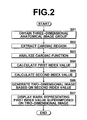
- Figure 2 is a flowchart illustrating a flow of a diagnosis assisting method performed by the diagnosis assisting program of the present embodiment.
- diagnosis assisting method of the present embodiment will be described with reference to Figure 2 .
- diagnosis assisting apparatus 1 When detects a selection of cardiac function diagnosis assisting function in a selection menu, diagnosis assisting apparatus 1 displays a list of subject IDs. When detects a user selection operation, image obtaining means 31 of diagnosis assisting apparatus 1, loads a group of three-dimensional anatomical images 7 in memory 3, as an image file related to the selected subject (S01).
- image obtaining means 31 obtains N t (integer not less than 2) three-dimensional anatomical images .7 representing structures of a heart at different phases.
- N t integer not less than 2
- a series of three-dimensional anatomical images taken at time T1, T 2 , -----, T Nt are obtained by imaging the subject at a constant time interval ⁇ T.
- image obtaining means 31 may obtain all of image files related to the selected subject. For example, in the case where a plurality of types of examinations (e.g., CT and SPECT examinations) have been performed and, as a result, a three-dimensional anatomical image 7 and a three-dimensional functional image 8 have been stored in storage 4, the two types of images may be loaded in memory 3.
- types of examinations e.g., CT and SPECT examinations
- First index value calculation means 32 performs a cardiac region extraction process on each three-dimensional anatomical image 7 constituting the obtained group of three-dimensional anatomical images 7 (S02).
- first and second index value calculation means For an overlapping process between the first and second index value calculation means, such as the case where the same three-dimensional anatomical image is used by the first and second index value calculation means, the process maybe performed by either one of them and the other of them may use the result.
- second index value calculation means 33 performs the cardiac region extraction process on the three-dimensional anatomical image or three-dimensional anatomical image group, or three-dimensional functional image 8.
- a three-dimensional anatomical image of which phase is required is dependent upon the type of second index. Therefore, in the case where three-dimensional images of different phases are required for calculating the second index, the cardiac region extraction process is performed on the three-dimensional anatomical image group, while in the case where a three-dimensional image at only one phase is required, the cardiac region extraction process may be performed only on the three-dimensional image.
- diagnosis assisting apparatus 1 calculates a characteristic amount representing likelihood of a contour of the heart and a characteristic amount representing a likelihood of a contour of the left ventricle with respect to a value of each voxel data constituting a three-dimensional anatomical image 7 and evaluates the calculated characteristic amounts based on an evaluation function obtained in advance by machine learning, thereby determining whether or not each voxel data represents a contour of the heart or a contour of the left ventricle (boundary between left ventricle and myocardium).
- voxel data representing a contour of the entire heart and voxel data representing a contour of the left ventricle are extracted.
- Adaboost algorithm is used for obtaining the evaluation function.
- a reference is made, for example, to Japanese Unexamined Patent Publication No. 2007-307358 .
- machine learning methods and statistical analysis methods such as linear discriminant method, neural network, support vector machine, and the like may be used for the extraction of the cardiac region.
- First index value calculation means 32 performs a cardiac function analysis process on the entire heart for the magnitude and direction of motion of each portion constituting the heart (S03) .
- Second index value calculation means 33 performs a cardiac function analysis process on a three-dimensional anatomical image 7 at a given phase or on a series of three-dimensional anatomical images 7 for calculating a second index value with respect to each portion constituting the heart.
- Figure 3 illustrates a long axis and cross-sections set in a cardiac function analysis process
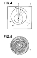
- Figure 4 illustrates an example evaluation value calculated in the cardiac function analysis process
- Figure 5 illustrates an example bull's eye image.
- the cardiac function analysis process will now be described in detail with reference to Figures 3 to 5 .
- first index value calculation means 32 and second index value calculation means 33 set a long axis A 1 , connecting the cardiac apex, approximate center of the left ventricle, and cardiac base, and a short axis A 2 perpendicular to the long axis A 1 in the extracted left ventricle region.
- the long axis A 1 is set automatically by calculating positional coordinates of the cardiac apex and center of the left ventricle from the result of cardiac region extraction process.
- the short axis A 2 is set so as to pass through the center of the left ventricle and is perpendicular to the long axis A 1 .
- the position or direction of the automatically set long axis may be changed by a user operation.
- the automatically set long axis is displayed on a screen with a cardiac region image, and the position or direction of the long axis may be changed by a drag operation or a rotating operation.
- first index value calculation means 32 and second index value calculation means 33 set a plurality of cross-sections P 1 to P N which is perpendicular to the long axis. Then, in each cross-section P 1 , a plurality of line segments l 1 to l m radially extending from an intersection point C of the long axis and the cross-section is defined, as illustrated in Figure 4 . Then, coordinate values of a boundary 19 between the left ventricle and myocardium and an outer wall 20 of the myocardium are obtained on each line segment l i and a myocardial wall thickness "t" is calculated from the coordinate values on each line segment l i .
- first index value calculation means 32 may use various methods for analyzing the motion of a heart. As an example, a method that performs local template matching to track how each portion of the cardiac wall moves, as in the tissue tracking method, may be employed. Further, a method that measures how each portion of the cardiac wall moves by projecting a grid pattern at the time of imaging by a MRI system and measuring deformation of the grid pattern, as in the tagging method, may also be employed.
- a process of analyzing motion of each portion of the cardiac wall is repeated by template matching between a three-dimensional anatomical image 7 at each time T i and a three-dimensional anatomical image 7 at time T i + ⁇ T (1 ⁇ i ⁇ N t ), and each time an evaluation value representing a cardiac motion is calculated.
- N t three-dimensional anatomical images for a heart for which three-dimensional anatomical images 7 of two or more phases are required for cardiac motion analysis, user may determine as to between which phases of three-dimensional anatomical images the cardiac motion is analyzed and may perform the aforementioned process.
- an amount of cardiac wall motion in a direction perpendicular to the direction radially extending from the center of the heart to the outside of the heart is calculated as the first index value (S04), and an amount of cardiac wall motion in the direction radially extending from the center of the heart to the outside of the heart is calculated as the second index value (S05).
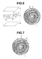
- Figure 6 illustrates a calculation method of a first index value to be superimposed on a two-dimensional image of the present embodiment.
- a comparison is made between a three-dimensional anatomical image at time T corresponding to a predetermined phase and a three-dimensional anatomical image at time T+ ⁇ T corresponding to a further phase and the myocardium is divided into a plurality of portions Q 1 , Q 2 , -----, Q m (m is an integer not less than 2) with respect to each cross-section P j (1 ⁇ j ⁇ N) of a plurality of cross-sections P 1 to P N perpendicular to the set long axis.
- an evaluation value representing the motion of each divided myocardial portion Qi is calculated as a vector V i constituted by a component V ai in "a" direction on the cross-section P j perpendicular to the direction from the intersection point C of the long axis and cross-section P j toward the myocardial portion Q i , a component V bi in "b" direction which is the direction from the intersection point C of the long axis and cross-section P j toward the myocardial portion Q i , and a component V ci in "c" direction perpendicular to the cross-section P j .
- the direction “a" on the cross-section P j perpendicular to the direction from the intersection point C of the long axis and cross-section P j toward the myocardial portion Q i is roughly corresponds to a circumferential direction of the heart so that the component V ai in the "a" direction on the cross-section P j roughly represents the motion of the heart in the circumferential direction on the cross-section P j .
- the component V ai in the "a" direction on the cross-section P j and component V ci in the "c" direction perpendicular to the cross-section P j of the vector V i are related respectively to a component V di in a circumferential direction "d” and a component V ei in a radial direction "e" of a corresponding portion Q i ' on a bull's eye image I to calculate a vector V i ' constituted by the component V di in the circumferential direction "d” and component V ei in the radial direction "e” of the portion Q i ' and represents the first index value.
- the component V bi not included in the first index value, in the direction "b" extending along the cross-section from the intersection point of the long axis and cross-section is calculated as the second index value at the portion Q i .
- the process of calculating the first and second index values is repeated for each myocardial portion Q i (1 ⁇ i ⁇ m) with respect to each cross-section P j (1 ⁇ j ⁇ N) of the plurality of cross-sections P i to P N perpendicular to the set long axis and whereby first and second index values are calculated for the entire heart.
- positional alignment of myocardial portion Q i is not required.
- the positional alignment of corresponding portions between the different volume data may be performed by various known methods, such as those described, for example, in Japanese Unexamined Patent Publication Nos. 2008-289799 and 2008-253753 .
- the first index value calculation process may be performed first or the second index value calculation process may be performed first, otherwise they may be performed simultaneously. Further, for an overlapping process between the first index value calculation process and the second index value calculation process, either one of the processing result may be utilized by the other.
- the second index value calculation means 33 In the case where second index value calculation means 33 does not use the processing result of the first index value calculation process for the second index value calculation process, such as the case where a membrane thickness variance is used as the second index value, the second index value calculation means 33 separately calculates an evaluation value for calculating the second index value by a known method, such as a method that obtains a difference in coordinate values between three-dimensional anatomical images 7 of different phases. This process may yield a three-dimensional functional image 8 in which evaluation values are disposed according to the shape of the heart. The generated three-dimensional functional image 8 is stored in memory 3.
- second index value calculation means 33 may be a means that calculates a plurality of types of evaluation values and generates a three-dimensional functional image 8 in which evaluation values are disposed according to the shape of the heart with respect to each of the plurality of types of evaluation values.
- second index value calculation means 33 may be a means that calculates the second index value that serves as a diagnostic indicator from the three-dimensional functional image instead of at least either one of a three-dimensional anatomical image at a given phase and a three-dimensional anatomical image group
- two-dimensional image generation means 34 may be a means that generates a two-dimensional image based on the calculated second index value.
- second index value calculation means 33 may use the data constituting the three-dimensional functional image 8 as the second index value without performing the cardiac function analysis process.
- Evaluation values represented by a three-dimensional functional image 8 include, for example, an evaluation value that can be calculated from a single three-dimensional anatomical image 7, such as the wall thickness.
- the evaluation values may further include those calculated by analyzing a plurality of time series three-dimensional anatomical images 7, such as the amount of wall movement, wall thickness variance, ejection fraction, and the like.
- the further obtained three-dimensional functional image 8 may be an image obtained as a result of a cardiac function analysis on a three-dimensional anatomical image 7, an image outputted from an imaging system for generating a functional image, such as a SPECT image or the like, or an image obtained by evaluation values which combine evaluation values outputted from an imaging system for generating a functional image, such as a SPECT image or the like, and evaluation values obtained from a three-dimensional anatomical image 7.
- two-dimensional image generation means 34 generates a two-dimensional image of the entire heart in which the second index value of each cardiac portion is disposed in a planar fashion.
- a bull' s eye image I is generatedbasedon second index values (SO6) .
- diagnosis assisting apparatus 1 generates a bull's eye image I by arranging second index values included in cross-sections P 1 to P N of a three-dimensional functional image 8 on circumferences of concentric circles having different radii with respect to each cross-section.
- An example bull's eye image I generated by such processing is shown in Figure 5 .
- display control means 35 displays the generated two-dimensional image on display 5 and superimposes marks representing the first index values calculated by the index value calculation means on the displayed two-dimensional image in a manner that allows the direction of motion of the first index values to be visually recognized (S07).
- Figure 7 shows an example bull's eye image I in which arrows representing vectors V 1 ' to V N ' which, in turn, represent first index values are displayed on a plurality of points disposed at a predetermined interval on circumferences of concentric circles having different radii with respect to each cross-section.
- display control means 35 superimposes an arrow representing a vector V i ' having a component V di in the circumferential direction and a component V ei in the radial direction on the bull' s eye image I as the first index value at each myocardial portion.
- marks representing first index values are superimposed on a two-dimensional image of the entire heart in which a second index value of each cardiac portion is disposed in a planar fashion in a manner that allows the direction of motion of the first index values to be visually recognized.
- This allows the index values that serve as diagnostic indicators of the entire heart and direction of motion of each cardiac portion to be displayed simultaneously on the displayed image.
- This allows the doctor or radiologist to confirm both the index values serving as diagnostic indicators of the entire heart and direction of motion of each cardiac portion on the displayed image, whereby the index values serving as diagnostic indicators of the entire heart and direction of motion of each cardiac portion may be easily understood. Consequently, motion of the cardiac wall may be understood easily without requiring any further processing, such as rotating the image or the like.
- first index values may be comprehended together with second index values represented by the two-dimensional image, so that an abnormality of cardiac function and the like may be estimated easily.
- display control means 35 displays marks representing first index values at a plurality of points regularly disposed in a two-dimensional image. This allows index values serving as diagnostic indicators of the entire heart and direction of motion of each cardiac portion to be displayed simultaneously on the displayed image and the direction of motion of each cardiac portion to be understood more easily.
- two-dimensional image generation means 34 of the diagnosis assisting apparatus of the present invention is a means that generates a bull's eye image I as the two-dimensional image, evaluation values serving as diagnostic indicators of the entire heart and direction of motion of each cardiac portion may be displayed simultaneously in the displayed bull's eye image I. This allows a doctor or a radiologist to confirm both the index values serving as diagnostic indicators of the entire heart and direction of motion of each cardiac portion in the displayed bull's eye image, whereby the index values serving as diagnostic indicators of the entire heart and direction of motion of each cardiac portion may be easily understood.
- the first index value may include any of all types of index values representing a direction and magnitude of each region of a cardiac wall between a three-dimensional image 7 at a given phase and a three-dimensional image 7 at a further phase. Further, the first index value may be a value of data constituting a three-dimensional functional image 8 or a bull's eye image I as long as it represents a direction and magnitude of the motion of each region of a cardiac wall or a value obtained as a result of certain analysis performed on the value of data.
- certain analysis may include, for example, obtaining an average value (including weighted average or the like), a maximum value, or a minimum value of each data of movement speed and acceleration of the cardiac wall between specific phases, such as from the end-diastole to the end-systole.
- index values of evaluation values constituting a three-dimensional functional image 8 or a bull's eye image I can be calculated and presented as the first index values:
- the second index value may be anything as long as it is an index value useful for diagnosis, and it may be a value of data constituting a three-dimensional functional image 8 or a bull' s eye image I, or a value obtained as a result of certain analysis performed on the value of data. For example, it may be a value obtained by the process of averaging (including weighted average or the like) each data constituting a three-dimensional anatomical image 7 or a three-dimensional functional image 8, or a value obtained by the process of obtaining a maximum or minimum value of the data. Further, the second index value may be the same index value as the first index value or a different index value from the first index value.
- index values of evaluation values constituting a three-dimensional functional image 8 or a bull's eye image I can be calculated and presented as the second index values:
- cardiac motion on each plane in the direction "a" perpendicular to the direction from the long axis of the heart toward each myocardial portion Q i of each cross-section may be displayed as one of the first index values representing each myocardial portion Q i of each cross-section, and cardiac motion in the direction "b" from the long axis of the heart toward each myocardial portion Q i may be displayed as the second index value.
- This allows a twisting motion of the heart to be displayed in an easily understandable manner on the displayed image, so that the doctor or the like may easily understand the twisting motion of the myocardium of the entire heart.
- the present embodiment may display motion of each cardiac portion in three directions on a two-dimensional image by the first index value, whereby the cardiac motion may be displayed in detail and accurately.
- the component Va in the direction "a" on a cross-section P j perpendicular to the direction "b" from the long axis of the heart to each myocardial portion Q i of each cross-section, which is one of the first index values representing each myocardial portion Q i of each cross-section may be related to the component V di in the circumferential direction "d" in the bull's eye image I, as illustrated in Figure 6 .
- display control means 35 may determine the magnitude of the component V ai in the circumferential direction as the length of the arrow.
- the component V a on each cross-section P j in a direction perpendicular to the direction "b" from the long axis of the heart toward each myocardial portion Q i and the component V b in the direction "b” from the long axis of the heart to each myocardial portion Q i may be related to the component V di in the circumferential direction "d" of the bull's eye image I and component V ei in the radial direction of the bull's eye image I respectively.
- display control means 35 may display each vector V i ' which includes the component V di in the circumferential direction and the component V ei in the radial direction.
- the doctor or the like may easily understand. twisting motion of the myocardium of the entire heart.
- the cardiac motion may be represented by a plurality of different representation methods, thereby allowing the doctor or the like to understand the cardiac motion in more detail.
- display control means 35 may display the arrow such that the greater the magnitude of the first index value, the wider the arrow. This allows the user to intuitively understand the magnitude of the first index value.
- the magnitude of a component in a direction not included in the vector V' or the magnitude of a vector formed by adding up each component, including a component in a direction not included in the vector V' may be numerically displayed adjacent to the arrow, or the magnitude of a component in a direction not included in the vector V' or the magnitude of a vector formed by adding up each component, including a component in a direction not included in the vector V', may be related to arrows having different widths, colors, shapes of arrow head or arrow feather in advance with respect to each range of the magnitudes, and the auxiliary information may be displayed in a visually recognizable manner by the width, color, shape of arrow head or arrow feather of each arrow. Still further, a different color may be disposed and displayed on each point of the mark according to the value of the first index.
- the display method is not limited to this, and marks representing first index values maybe displayed in different colors with respect to direction or magnitude of motion of each cardiac portion by various methods according to the user requirements.
- image obtaining means 31 may be a means that further obtains a three-dimensional functional image 8 in which evaluation values for evaluating the cardiac function are disposed three-dimensionally according to the shape of the organ
- second index value calculation means 33 may be a means that calculates the second index value that serves as a diagnostic indicator from the three-dimensional functional image instead of at least either one of the three-dimensional anatomical image at a given phase and the three-dimensional anatomical image group.
- index values for evaluating cardiac function and the direction of motion of each cardiac portion for the entire heart may be displayed simultaneously on the displayed image. This allows the doctor or radiologist to confirm both the index values for evaluating the cardiac function and direction of motion of each cardiac portion on the displayed image and to easily understand the evaluation values for evaluating the cardiac function and direction of each cardiac portion for the entire heart.
- two-dimensional image generation means 34 generates a two-dimensional image to which first index values are related
- display control means 35 displays the two-dimensional image on display 5, whereby marks representing the first index values are superimposed on the two-dimensional image in a manner that allows the direction of motion of each first index value to be visually recognized.
- the method is not limited to this, and a method that separately generates a two-dimensional image based on first index values and a two-dimensional image based on second index values and displays the images in a superimposing manner if the method is capable of superimposing the generated two-dimensional image and marks representing first index values in a manner that allows the direction of motion of each first index value to be visually recognized.
- Figures 8 and 9 illustrate examples of different marks representing first index values.
- Figure 8 is an example bull's eye image I on which a grid representing the first index value of the present embodiment is superimposed
- Figure 9 is an example Bull's eye image I on which a trajectory representing the first index value of the present embodiment is superimposed.
- display control means 35 may shift each of a plurality of points disposed on a two-dimensional image so as to form a regular grid, as shown in the drawing on the left of Figure 8 , to a position based the magnitude and direction of the first index value at each position, as shown in the drawing on the right of Figure 8 , and display the shifted positions as the marks representing the first index values.
- the direction of motion of each cardiac portion may be easily understood.
- marks each representing the first index value, may be displayed on a two-dimensional image in combination with each other.
- the grid shown on the right of Figure 8 and the arrows shown in Figure 7 may be displayed in a bull's eye image.
- Use of a plurality of marks allows the cardiac motion to be displayed by various representation methods, leading to better user understanding.
- display control means 35 may display trajectories of a plurality of points in a two-dimensional image due to changes in cardiac phase, as shown in Figure 9.
- Figure 9 is an imaginary drawing indicating a trajectory of each of a plurality of points disposed at a predetermined interval in concentric circles having different radii in a bull's eye image I due to changes in the phase from the end-diastole to end-systole.
- the direction of motion of each cardiac portion may be understood easily.
- each trajectory may be gradationally displayed according to the speed, acceleration, or the like in each phase on the trajectory, for example, such that the greater the speed or acceleration, the greater the color density of the trajectory. In this case, not only the movement of each position according to the phase changes but also other motions such as the speed, acceleration, and the like may be displayed, so that cardiac motion can be understood in more detail.
- first index value calculation means 32 calculates, with respect to N t three-dimensional anatomical images 7, first index values from each three-dimensional anatomical image 7 and a three-dimensional anatomical image 7 in the successive phase of each three-dimensional anatomical image 7.
- two-dimensional image generation means 34 is a means that generates a two-dimensional image to which first index values in each phase are related in a time series manner
- display control means 35 is a means that displays the marks at each phase in a time series manner.
- the cardiac motion that varies with each phase can be understood easily as well as the index values that serve as diagnostic indicators for the entire heart and direction of motion of each cardiac portion may be displayed simultaneously on the displayed image.
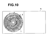
- Figure 10 illustrates an example modification of the first embodiment.
- the diagnosis assisting apparatus of the present embodiment may accept specification of a mark superimposed on a bull's eye image I and display a tomographic image at the position corresponding to the specified mark.
- the user may move the cursor S and click on an arbitrary position of an arrow shown in the bull' s eye image I with a mouse or the like and the apparatus may display a tomographic image P k which includes the position corresponding to the position of the base of the clicked arrow.
- a position in the length direction of an arrow in the bull's eye image I may be related to a predetermined time along the phase change.
- each position in the length direction of an arrow may be related to each phase along a predetermined temporal progress such that the base of the arrow corresponds to the end-diastole and the arrow head corresponds to the end-systole.
- a tomographic image of a three-dimensional anatomical image at the phase corresponding to the position of the clicked arrow and includes the position corresponding to the position of the arrow base is displayed and an image corresponding to a tomographic image which includes the position corresponding to the position of the base of the arrow in the successive phase is displayed as a motion image in a time series manner.
- the time series motion image display period may be determined according to the dragged distance or time. That is, the ratio of reproduction time to a predetermined time is related to each dragged distance or time in advance and the tomographic image which includes the position corresponding to the position of the arrow base is displayed by the time related to the dragged distance or time from the phase corresponding to the position of the clicked arrow, and the image corresponding to the tomographic image which includes the position of the arrow base in the successive phase is displayed as a motion image in a time series manner.
- Diagnosis assisting apparatus 1 may further includes a coronary artery extraction means to extract a coronary artery by one of the various known methods and superimpose the extracted coronary artery region on the screen of the display device by any known method of displaying a coronary artery on a bull' s eye image I in a superimposing manner as described, for example, in Japanese Unexamined Patent Publication Nos. 2005-027999 and 2008-253753 .
- diagnosis assisting apparatus 1 is configured to allow the user to correct the route of the displayed coronary artery or to manually set a portion of the route not extracted by the automatic extraction on the screen.
- diagnosis assisting apparatus 1 is capable of detecting a user operation on the screen, correcting information of the coronary artery stored in the memory based on the user operation, and updating the coronary artery region displayed on the screen based on the corrected information.
- the diagnosis assisting apparatus is configured to control the type of mark displayed on the screen and display timing (display switching) by referring to mark setting information stored in memory 3 or by detecting menu selection operation by the user.
- the display control means allows a mark representing the first index to be selectable through a GUI or the like and detects a user selection operation to perform the following display operations. That is, when an arrow is specified as the mark of the first index, the display control means displays first index values by arrows on a bull' s eye image I in a superimposing manner, when a trajectory of each portion is specified as the mark of the first index, the display control means displays first index values by the trajectory of each point on the bull's eye image I in a superimposing manner, and when a grid pattern is specified as the mark of the first index, the display control means displays a pattern formed by shifting a plurality of points disposed so as to form a regular grid based on the first index values on the bull's eye image I in a superimposing manner.
- Diagnosis assisting apparatus 1 determines whether or not to perform a superimposing display on a bull's eye image I and with which mark the superimposing display is performed according to information set in the apparatus or user operation.
- second index value calculation means 33 may be a means that calculates different types of second index values
- two-dimensional image generation means 34 may be a means that generates a two-dimensional image with respect to each of different types of second index values
- display control means 35 may be a means that displays the marks representing first index values on a two-dimensional image desired by the user in a superimposing manner.
- a bull's eye image I is generated such that values obtained from the cross-section P N closest to the cardiac apex are disposed on a circle having a smallest radius and values obtained from the cross-section P i most remote from the cardiac apex are disposed on a circle having a largest radius, with the cardiac apex as the center of the concentric circles.
- the bull's eye may be generated such that values obtained from the cross-section P i are disposed on a circle having a smallest radius and values obtained from the cross-section P N are disposed on a circle having a largest radius, with the cardiac base as the center of the concentric circles.
- various other modifications are known and any of the methods may be used in the present invention.
- diagnosis assisting apparatus 1 is formed of a single computer on which each program is installed. But a diagnosis assisting system that can realize functions identical to those of diagnosis assisting apparatus 1 may be constructed by distributing and installing respective programs on a plurality of computers.
- diagnosis assisting apparatus 1 may include a means for performing print output or data output (recording on a medium, such as .CD-R or DVD, or transfer via network) other than display output. That is, in the present invention, the output form of index values is not limited to the display output.
Landscapes
- Engineering & Computer Science (AREA)
- Physics & Mathematics (AREA)
- General Physics & Mathematics (AREA)
- Theoretical Computer Science (AREA)
- Computer Vision & Pattern Recognition (AREA)
- Medical Informatics (AREA)
- General Health & Medical Sciences (AREA)
- Nuclear Medicine, Radiotherapy & Molecular Imaging (AREA)
- Radiology & Medical Imaging (AREA)
- Quality & Reliability (AREA)
- Health & Medical Sciences (AREA)
- Multimedia (AREA)
- Magnetic Resonance Imaging Apparatus (AREA)
- Apparatus For Radiation Diagnosis (AREA)
Applications Claiming Priority (1)
| Application Number | Priority Date | Filing Date | Title |
|---|---|---|---|
| JP2010229300A JP5323795B2 (ja) | 2010-10-12 | 2010-10-12 | 診断支援装置、診断支援プログラムおよび診断支援方法 |
Publications (2)
| Publication Number | Publication Date |
|---|---|
| EP2442277A2 true EP2442277A2 (fr) | 2012-04-18 |
| EP2442277A3 EP2442277A3 (fr) | 2014-02-12 |
Family
ID=44862529
Family Applications (1)
| Application Number | Title | Priority Date | Filing Date |
|---|---|---|---|
| EP11184725.7A Withdrawn EP2442277A3 (fr) | 2010-10-12 | 2011-10-11 | Appareil d'aide au diagnostic, programme d'aide au diagnostic et procédé d'aide au diagnostic |
Country Status (3)
| Country | Link |
|---|---|
| US (1) | US20120089016A1 (fr) |
| EP (1) | EP2442277A3 (fr) |
| JP (1) | JP5323795B2 (fr) |
Families Citing this family (15)
| Publication number | Priority date | Publication date | Assignee | Title |
|---|---|---|---|---|
| CN102231963B (zh) * | 2008-12-03 | 2014-09-24 | 皇家飞利浦电子股份有限公司 | 重新参数化的牛眼图 |
| US9858687B2 (en) * | 2012-01-17 | 2018-01-02 | Emory University | Systems, methods, and computer readable storage media storing instructions for generating an image integrating functional, physiological and anatomical images |
| JP2015526149A (ja) * | 2012-07-18 | 2015-09-10 | コーニンクレッカ フィリップス エヌ ヴェ | 局部収縮測定 |
| WO2014081021A1 (fr) * | 2012-11-22 | 2014-05-30 | 株式会社東芝 | Dispositif de traitement d'image, appareil d'imagerie par résonance magnétique, et procédé de traitement d'image |
| JP5992848B2 (ja) * | 2013-03-06 | 2016-09-14 | 富士フイルム株式会社 | 体動表示装置および方法 |
| US9949643B2 (en) * | 2014-10-18 | 2018-04-24 | International Business Machines Corporation | Automatic visualization of regional functional parameters of left ventricle from cardiac imaging |
| KR102531117B1 (ko) | 2015-10-07 | 2023-05-10 | 삼성메디슨 주식회사 | 대상체를 나타내는 영상을 디스플레이하는 방법 및 장치. |
| GB201610269D0 (en) | 2016-06-13 | 2016-07-27 | Isis Innovation | Image-based diagnostic systems |
| JP6724154B2 (ja) * | 2016-10-05 | 2020-07-15 | 富士フイルム株式会社 | プロセッサ装置及び内視鏡システム並びにプロセッサ装置の作動方法 |
| US20190021677A1 (en) * | 2017-07-18 | 2019-01-24 | Siemens Healthcare Gmbh | Methods and systems for classification and assessment using machine learning |
| JP6862310B2 (ja) * | 2017-08-10 | 2021-04-21 | 株式会社日立製作所 | パラメータ推定方法及びx線ctシステム |
| JP6643416B2 (ja) * | 2018-08-01 | 2020-02-12 | キヤノン株式会社 | 画像処理装置、画像処理方法およびプログラム |
| WO2020044523A1 (fr) * | 2018-08-30 | 2020-03-05 | オリンパス株式会社 | Dispositif d'enregistrement, dispositif d'observation d'images, système d'observation, procédé de commande de système d'observation, et programme de fonctionnement de système d'observation |
| US11734837B2 (en) * | 2020-09-30 | 2023-08-22 | Shanghai United Imaging Intelligence Co., Ltd. | Systems and methods for motion estimation |
| CN114145763B (zh) * | 2021-11-24 | 2026-02-24 | 上海友脉科技有限责任公司 | 心脏期相判断装置、方法、介质及电子设备 |
Citations (6)
| Publication number | Priority date | Publication date | Assignee | Title |
|---|---|---|---|---|
| JP2002306483A (ja) | 2001-04-18 | 2002-10-22 | Toshiba Corp | 医用画像診断装置及びその方法 |
| JP2005027999A (ja) | 2003-07-10 | 2005-02-03 | Ziosoft Inc | 画像解析装置および画像解析プログラムおよび画像解析方法 |
| JP2007307358A (ja) | 2006-04-17 | 2007-11-29 | Fujifilm Corp | 画像処理方法および装置ならびにプログラム |
| JP2008253753A (ja) | 2007-03-14 | 2008-10-23 | Fujifilm Corp | 心機能表示装置およびそのプログラム |
| JP2008289799A (ja) | 2007-05-28 | 2008-12-04 | Fujifilm Corp | 心臓機能解析装置、方法およびそのプログラム |
| US20090043200A1 (en) | 2007-08-10 | 2009-02-12 | Yasuhiko Abe | Ultrasonic diagnostic apparatus, ultrasonic image processing apparatus, and ultrasonic image processing method |
Family Cites Families (9)
| Publication number | Priority date | Publication date | Assignee | Title |
|---|---|---|---|---|
| JP4596759B2 (ja) * | 2002-09-12 | 2010-12-15 | 株式会社日立メディコ | 画像診断装置、及び画像診断装置の作動方法 |
| JP4750429B2 (ja) * | 2005-02-08 | 2011-08-17 | 株式会社日立メディコ | 画像表示装置 |
| JP2006239195A (ja) * | 2005-03-04 | 2006-09-14 | Fuji Photo Film Co Ltd | コンピュータによる画像診断支援方法および画像診断支援装置ならびにプログラム |
| US7940978B2 (en) * | 2007-06-05 | 2011-05-10 | General Electric Company | Automatic characterization of cellular motion |
| JP5523681B2 (ja) * | 2007-07-05 | 2014-06-18 | 株式会社東芝 | 医用画像処理装置 |
| JP2009018005A (ja) * | 2007-07-11 | 2009-01-29 | Toshiba Corp | ブルズアイマップ作成装置、ブルズアイマップ作成方法、及び画像処理装置 |
| WO2009072397A1 (fr) * | 2007-12-07 | 2009-06-11 | Konica Minolta Medical & Graphic, Inc. | Système d'imagerie dynamique |
| JP5454844B2 (ja) * | 2008-08-13 | 2014-03-26 | 株式会社東芝 | 超音波診断装置、超音波画像表示装置及び超音波画像表示プログラム |
| WO2010020933A2 (fr) * | 2008-08-20 | 2010-02-25 | Koninklijke Philips Electronics N.V. | Traitement de données cardiaques pour diagramme aha personnalisé |
-
2010
- 2010-10-12 JP JP2010229300A patent/JP5323795B2/ja not_active Expired - Fee Related
-
2011
- 2011-10-11 US US13/270,871 patent/US20120089016A1/en not_active Abandoned
- 2011-10-11 EP EP11184725.7A patent/EP2442277A3/fr not_active Withdrawn
Patent Citations (6)
| Publication number | Priority date | Publication date | Assignee | Title |
|---|---|---|---|---|
| JP2002306483A (ja) | 2001-04-18 | 2002-10-22 | Toshiba Corp | 医用画像診断装置及びその方法 |
| JP2005027999A (ja) | 2003-07-10 | 2005-02-03 | Ziosoft Inc | 画像解析装置および画像解析プログラムおよび画像解析方法 |
| JP2007307358A (ja) | 2006-04-17 | 2007-11-29 | Fujifilm Corp | 画像処理方法および装置ならびにプログラム |
| JP2008253753A (ja) | 2007-03-14 | 2008-10-23 | Fujifilm Corp | 心機能表示装置およびそのプログラム |
| JP2008289799A (ja) | 2007-05-28 | 2008-12-04 | Fujifilm Corp | 心臓機能解析装置、方法およびそのプログラム |
| US20090043200A1 (en) | 2007-08-10 | 2009-02-12 | Yasuhiko Abe | Ultrasonic diagnostic apparatus, ultrasonic image processing apparatus, and ultrasonic image processing method |
Non-Patent Citations (1)
| Title |
|---|
| "Three-Dimensional Display of Positron Emission Tomography of the Heart", THE JOURNAL OF NUCLEAR MEDICINE, vol. 29, 1988, pages 530 - 537 |
Also Published As
| Publication number | Publication date |
|---|---|
| JP5323795B2 (ja) | 2013-10-23 |
| JP2012081037A (ja) | 2012-04-26 |
| US20120089016A1 (en) | 2012-04-12 |
| EP2442277A3 (fr) | 2014-02-12 |
Similar Documents
| Publication | Publication Date | Title |
|---|---|---|
| US20120089016A1 (en) | Diagnosis assisting apparatus, diagnosis assisting program, and diagnosis assisting method | |
| US8422752B2 (en) | Diagnosis assisting apparatus, diagnosis assisting method, and storage medium in which a diagnosis assisting program is recorded | |
| JP5976431B2 (ja) | 運動対象輪郭トラッキング装置及び運動対象輪郭トラッキング方法 | |
| JP5944645B2 (ja) | 磁気共鳴イメージング装置 | |
| EP4224418B1 (fr) | Analyse de flux dans des données d'image mr 4d | |
| EP3886702B1 (fr) | Sélection d'image radiographique la plus pertinente pour une simulation hémodynamique | |
| JP5954769B2 (ja) | 医用画像処理装置、医用画像処理方法および異常検出プログラム | |
| US8907952B2 (en) | Reparametrized bull's eye plots | |
| CN114173649B (zh) | 用于分析诊断图像数据的方法和装置 | |
| US8824755B2 (en) | Method and computer system for automatically generating a statistical model | |
| EP1846896B1 (fr) | Procede, systeme, et programme permettant l'integration d'informations diagnostiques medicales avec un modele geometrique d'un corps mobile | |
| EP2443998A1 (fr) | Appareil d'assistance de diagnostic d'image médicale, procédé et programme | |
| CN110546646A (zh) | 用于基于机器学习来评估血管阻塞的方法和系统 | |
| JP5700964B2 (ja) | 医用画像処理装置、方法およびプログラム | |
| US8165378B2 (en) | Method and apparatus for visualizing tubular anatomical structures, in particular vessel structures, in medical 3D image records | |
| WO2010020933A2 (fr) | Traitement de données cardiaques pour diagramme aha personnalisé | |
| JP5415245B2 (ja) | 医用画像表示装置および方法並びにプログラム | |
| WO2013140750A1 (fr) | Dispositif de contrôle d'affichage d'image médicale, procédé et programme | |
| JP4837579B2 (ja) | 画像処理装置、画像処理方法、およびプログラム | |
| JP6898047B2 (ja) | 時変データの定量的評価 | |
| WO2010001327A1 (fr) | Traitement de données d'anatomie et d'analyse quantitative associée de tissu | |
| JP6258403B2 (ja) | 医用画像表示制御装置および方法並びにプログラム | |
| JP2009018029A (ja) | 医用画像処理装置及び医用画像診断装置 | |
| JP2022073262A (ja) | 医用画像処理装置、医用画像処理方法及びプログラム | |
| JP2017029290A (ja) | 画像処理装置、方法、及びプログラム |
Legal Events
| Date | Code | Title | Description |
|---|---|---|---|
| PUAI | Public reference made under article 153(3) epc to a published international application that has entered the european phase |
Free format text: ORIGINAL CODE: 0009012 |
|
| AK | Designated contracting states |
Kind code of ref document: A2 Designated state(s): AL AT BE BG CH CY CZ DE DK EE ES FI FR GB GR HR HU IE IS IT LI LT LU LV MC MK MT NL NO PL PT RO RS SE SI SK SM TR |
|
| AX | Request for extension of the european patent |
Extension state: BA ME |
|
| PUAL | Search report despatched |
Free format text: ORIGINAL CODE: 0009013 |
|
| AK | Designated contracting states |
Kind code of ref document: A3 Designated state(s): AL AT BE BG CH CY CZ DE DK EE ES FI FR GB GR HR HU IE IS IT LI LT LU LV MC MK MT NL NO PL PT RO RS SE SI SK SM TR |
|
| AX | Request for extension of the european patent |
Extension state: BA ME |
|
| RIC1 | Information provided on ipc code assigned before grant |
Ipc: G06T 11/20 20060101ALI20140109BHEP Ipc: G06T 7/20 20060101ALI20140109BHEP Ipc: G06T 7/00 20060101AFI20140109BHEP |
|
| 17P | Request for examination filed |
Effective date: 20140806 |
|
| RBV | Designated contracting states (corrected) |
Designated state(s): AL AT BE BG CH CY CZ DE DK EE ES FI FR GB GR HR HU IE IS IT LI LT LU LV MC MK MT NL NO PL PT RO RS SE SI SK SM TR |
|
| STAA | Information on the status of an ep patent application or granted ep patent |
Free format text: STATUS: THE APPLICATION HAS BEEN WITHDRAWN |
|
| 18W | Application withdrawn |
Effective date: 20150526 |