EP2443312B1 - Universeller drehausbruchskopf mit geschmiertem modualrem lagerblock - Google Patents
Universeller drehausbruchskopf mit geschmiertem modualrem lagerblock Download PDFInfo
- Publication number
- EP2443312B1 EP2443312B1 EP09845956.3A EP09845956A EP2443312B1 EP 2443312 B1 EP2443312 B1 EP 2443312B1 EP 09845956 A EP09845956 A EP 09845956A EP 2443312 B1 EP2443312 B1 EP 2443312B1
- Authority
- EP
- European Patent Office
- Prior art keywords
- seal
- bearing pack
- sealing
- bearing
- assembly
- Prior art date
- Legal status (The legal status is an assumption and is not a legal conclusion. Google has not performed a legal analysis and makes no representation as to the accuracy of the status listed.)
- Active
Links
Images










Classifications
-
- E—FIXED CONSTRUCTIONS
- E21—EARTH OR ROCK DRILLING; MINING
- E21B—EARTH OR ROCK DRILLING; OBTAINING OIL, GAS, WATER, SOLUBLE OR MELTABLE MATERIALS OR A SLURRY OF MINERALS FROM WELLS
- E21B33/00—Sealing or packing boreholes or wells
- E21B33/02—Surface sealing or packing
- E21B33/08—Wipers; Oil savers
- E21B33/085—Rotatable packing means, e.g. rotating blow-out preventers
-
- E—FIXED CONSTRUCTIONS
- E21—EARTH OR ROCK DRILLING; MINING
- E21B—EARTH OR ROCK DRILLING; OBTAINING OIL, GAS, WATER, SOLUBLE OR MELTABLE MATERIALS OR A SLURRY OF MINERALS FROM WELLS
- E21B33/00—Sealing or packing boreholes or wells
- E21B33/02—Surface sealing or packing
- E21B33/08—Wipers; Oil savers
Definitions
- Embodiments of the invention relate to rotating control devices for well operations and more particularly to a modular assembly having bearings, sealing assemblies and a rotatable quill, the modular assembly being removeably secured within a stationary housing.
- the rotating control device serves multiple purposes including sealing off tubulars moving in an out of a wellbore and accommodating rotation of the same.
- Tubulars can include a kelly, pipe or other drill string components.
- the rotating control device is an apparatus used for well operations and diverts fluids such as drilling mud, surface injected air or gas and produced wellbore fluids, including hydrocarbons, into a recirculating or pressure recovery mud system.
- Typical in-service time numbers in the tens to low hundreds of hours before some part of the operation requires service or other attention including drill bit replacement or other downhole equipment such as motors, turbines and measurement while drilling systems. It is desirable that a rotating control device last as long as other components and not be the reason operations are interrupted and result in nonproductive time (NPT).
- NPT nonproductive time
- a rotating flow head of the present invention comprises a lubricated seal system to improve the longevity of the rotating flow head bearings and sealing elements, and a unique assembly for providing a structurally low profile rotating flow head.
- aspects of the present invention provide a user-friendly device and contribute to significant increases in the mean time between failures in a difficult environment, known in the industry to number only in the hundreds of hours before expensive servicing is required.
- a rotating flow head housing is secured to a wellhead and has an assembly bore in communication with a wellbore.
- the assembly bore is replaceably fit with a lubricated bearing pack for rotatably sealing tubulars extending therethrough.
- the bearing pack has a bearing pack housing and an axially rotatable inner cylindrical sleeve or quill adapted for the passage of drill string tubulars forming an annular bearing assembly space therebetween.
- Bearing elements are positioned in the annular assembly space for radially and axially supporting the inner cylindrical sleeve within the bearing pack housing and two or more sealing elements and a stripper element seal the bearing elements from wellbore fluids,
- each of the two or more sealing elements has an elastomeric body operable between a first non-activated state and a second activated state. When activated, the elastomeric body of each sealing ring engages the quill for sealing thereto.
- the elastomeric body further has an annular cavity, an inner surface adapted to engage the quill, and a radially outwardly extending member supported in the bearing pack housing.
- the radially outwardly extending member When the elastomeric body is in its first non-activated state, the radially outwardly extending member has a first radial extent being less than the radial extent of the bearing assembly space, forming a radial seal clearance; and when the elastomeric body is in its second activated state, the radially outwardly extending member is axially compressed, distending radially outwardly and substantially freely into the radial seal clearance and avoiding a jamming of the seal against the quill.
- the axial bearings and the radial bearings are provided in pairs, the pair of radial bearings being fit to the annular assembly space with axial clearance to avoid introducing complex loading and the pair of axial bearings being fit to the annular assembly space with radial clearance to avoid complex loading.
- the bearing pack is retained within the rotating flow head housing using a retainer plate removeably secured over an installed bearing pack in the annular assembly space using a plurality of circumferentially spaced lag bolts engaged radially through the housing.
- a portion of the quill adjacent the sealing elements is fit with sacrificial replaceable wear sleeves so as to enable periodic replacement without need to replace the quill itself.
- the two or more seal elements between the bearings and the wellbore have at least one seal element oriented for sealing against wellbore fluid ingress from the wellbore to the bearings and at least seal element for sealing against egress of bearing lubricants from the bearings to the wellbore.
- a rotating flow head generally comprises a stationary housing adapted for incorporation onto a wellhead and a rotating cylindrical sleeve, such as a quill or mandrel, for establishing a seal to a movable tubular such as tubing, drill pipe or kelly.
- the quill is rotatably and axially supported by a lubricated bearing pack comprising bearing elements and seal assemblies for isolating the bearing elements from pressurized wellbore fluids.
- a rotating flow head 1 comprises a stationary housing 2 adapted at a lower end by a flange connection 3, to operatively connect to a wellhead or a blow out preventer (not shown).
- the stationary housing 2 can be fit with one or more outlets 4 along a side portion of the stationary housing 2 for the discharge of wellbore fluids.
- the stationary housing 2 has an assembly bore 5 fit with a modular internal assembly 10 which includes a quill 11 and a bearing pack 20 having seals.
- the quill 11 comprises a tubular quill shaft 13 having an elastomeric stripper element 14 supported at a downhole end of the tubular shaft 13.
- the elastomeric stripper element 14 is adapted to seal to tubulars passing therethrough.
- An annular space is formed between the stationary housing 2 and the quill shaft 13.
- the bearing pack 20 is positioned in the annular space for axially and rotationally supporting the quill 11 in the stationary housing 2.
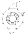
- the retainer plate 6 can be a threaded screw cap, as shown in Fig. 2 or, as shown in Fig. 1B , can comprise a thrust plate 50 secured by a plurality lag bolts 55 distributed or circumferentially spaced about an upper end of the stationary housing 2.
- the thrust plate 50 reduces the overall structural height of the rotating flow head 1.
- the low structural profile of the rotating flow head 1 allows for greater freedom and ease of movement underneath a rotary table.
- the lag bolts 55 are manually or hydraulically adjustable radially inward and have a distal end 56 which impinges on the assembly bore 5 of the stationary housing 2 and retain the thrust plate 50 or adjustable radially outward to release the thrust plate 50 for removal and removal of the bearing pack 20.
- Typical well operations may involve the passing of tubulars through a rotary table having a bore of about 445mm (17.5 inches) in diameter.
- the thrust plate 50 in order to pass through a working bore of a rotary table, should have a diameter no greater than 445mm (17.5 inches).
- the thrust plate 50 may be of a split design, comprising multiple pieces, such as two halves, which can be installed about the tubular to secure the internal assembly 10 within the assembly bore 5 of the stationary housing 2. This obviates the need to pass a retainer plate 6 through the working bore of the rotary table.
- a thrust plate 50 comprises a cylindrical ring, sized to fit within the assembly bore 5.
- the lag bolts 55 are manually or hydraulically actuated to engage the thrust plate 50 to secure the bearing pack 20 within the assembly bore 5.
- the thrust plate 50 may have a plurality of mating surfaces 51, on an upper surface of the thrust plate, which may be indentations, spaced circumferentially thereabout and which correspond to the distal ends 56 of each of the lag bolts 55.
- the distal ends 56 can be tapered so that when they engage the mating surfaces 51, the lag bolts impose an axial load onto the thrust plate 50, securing the trust plate 50 in firm, dimensional relation to the stationary housing 2 and the bearing pack 20.
- each of the mating surfaces 51 can comprise a single semi-spherical side wall 52 and a terminating back wall 53. In alternate embodiments the mating surfaces 51 can comprise a plurality of side walls.
- the thrust plate 50 can also be rotationally restrained or even attached to the bearing pack 20 such as by set screws (not shown).
- the plurality of circumferentially spaced mating surfaces 51 accept the lag bolts 55, which can be manually or hydraulically actuated through the stationary housing 2, for securing the internal assembly 10 within the assembly bore 5 of the stationary housing 2.
- the lag bolts 55 can be manually or hydraulically actuated through the stationary housing 2, for securing the internal assembly 10 within the assembly bore 5 of the stationary housing 2.
- by restraining the bearing pack rotationally to the thrust plate 50 and the accepting of the lag bolts 55 within the mating surfaces 51 also prevent rotational movement of the bearing pack 20 relative to the stationary housing 2.
- the bearing pack 20 can be releaseably fit as a module or internal assembly 10 into the assembly bore 5 of the stationary housing 2.
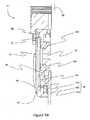
- the internal assembly 10 comprises an outer bearing housing 15 having bearings 21, a lower seal assembly 40 having at least two sealing elements, and an upper seal assembly 80 having at least one sealing element, for replacement as a single unit or module.
- the outer bearing housing 15 may have a tapered lower end 16 which is supported upon the shoulder 17 in the assembly bore 5 of the stationary housing 2 and retained therein by the retainer plate 6.
- the outer bearing housing 15 has a radially inward shoulder 18 and the quill shaft 13 has a radially outward shoulder 19 which cooperate with the bearing pack 20 to axially and rotationally support the quill 11 in the outer bearing housing 15.
- the stripper element elastomeric is attached to a downhole portion of the quill shaft 13.
- the quill shaft 13 is fit with sacrificial replaceable quill wear sleeves 90a, 90b.
- a downhole sacrificial quill wear sleeve 90a envelopes that portion of the quill shaft 13 that engages the lower seal assembly 40 and bearing element 21a.
- An uphole sacrificial replaceable quill wear sleeve 90b envelopes that portion of the quill shaft 13 that engages the upper seal assembly 80 and bearing element 21d.
- the sacrificial quill wear sleeves 90a, 90b can be readily available on site and are easily replaceable once worn due to prolonged operations. Instead of having to replace an entire rotating quill 11, a quick replacement of the sacrificial quill wear sleeves 90a, 90b reduces nonproductive time and thus saves operational time and costs.
- the outer bearing housing 15 and the quill shaft 13 define an annular assembly space therebetween for supporting bearing elements 21a, 21b, 21c, 21d and seal assemblies 40, 80.
- the quill shaft 13 is axially and radially supported within the outer bearing housing 15 by bearing elements 21 a, 21 b, 21 c, 21 d.
- Lower seal assembly 40 is located downhole from the bearing elements 21 a, 21 b, 21 c, 21 d, while upper seal assembly 80 is located uphole of the bearing elements 21 a, 21 b, 21 c, 21 d.
- the outer bearing housing 15 houses bearing elements 21a, 21b, 21c and lower seal assembly 40.
- Lower seal assembly 40 isolates wellbore fluids from the bearings elements 21 a, 21 b, 21 c.
- the lower seal assembly 40 can comprise one or more seal elements 41 a, 41 b, 41 c.
- the bearing elements 21 a, 21 b, 21 c are selected from heavy duty bearings for rotationally and axially supporting loads resulting from wellbore pressure and tubular movement.
- the bearing elements 21 a, 21 b, 21 c handle radial loads, downhole loading and uphole loading respectively.
- the bearing elements 21a, 21 b, 21 c between the outer bearing housing 15 and the quill shaft 13 are provided with a first lubricant which can be circulated for cooling the bearings and surrounding area.
- the internal assembly 10 houses a fourth bearing element 21 d, for handing radial loading, and a second upper seal assembly 80.
- Upper seal assembly 80 can comprise two sealing elements 81a, 81b, which aid lower seal assembly 40 with sealing wellbore fluids from the bearing elements 21 a, 21 b, 21 c, 21d.
- Sealing elements 81 a, 81b are the same as sealing elements 41 a, 41 b, 41 c, except for being smaller in dimensions.
- Bearing elements 21 a and 21 d such as cross roller bearings, radially support the quill 11.
- Bearing elements 21b and 21 c such as thrust bearings, axially support the quill 11.
- the radial movement of the quill 11 has been isolated from the axially movement of the quill 11.
- the axial tolerances above and below radial load bearing elements 21 a and 21 d are provided to allow axial movement of bearing elements 21 a and 21 d.
- the radial tolerances adjacent axial load bearing elements 21 b and 21 c are also provided, allowing for radial movement of bearing elements 21 b and 21 c.
- An isolation thrust plate 82 between cross roller bearing element 21 d and thrust bearing element 21 c also aids in isolating the axial movement of the quill 11 from the radial movement.
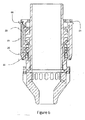
- the bearing elements 21a, 21b, 21c, 21d are in fluid communication with a bearing lubricant passageway 23 (shown in Fig. 6 ) for directing a bearing lubricant under pressure to the bearing elements 21a, 21b, 21 c, 21 d.
- the bearing lubricant passageway 23 forms a discrete and independent bearing fluid system.
- the bearing lubricant, stored on the surface in a bearing lubrication tank, can be continuously flushed through the bearing fluid system to lubricate and cool the bearing elements 21a, 21b, 21c, 21d.
- a heat exchanger can be provided to provide extra cooling of the bearing lubricant.
- the lower seal assembly 40 can comprise three sealing elements 41 a, 41 b, 41 c which isolates the bearing elements 21 a, 21b, 21c from wellbore fluids.
- the wellbore pressure can be very high, threatening the integrity of the sealed bearings.
- the pressure in the wellbore could drop below some maintenance pressure of the bearings lubricant, threatening loss of lubricant to the wellbore.
- the lower seal assembly 40 between the bearings and the wellbore, have at least one sealing element 41 d oriented for sealing against wellbore fluid ingress WF from the wellbore to the bearings and the at least one sealing element 41 d for sealing against the egress LF of pressurized bearing lubricants from the bearings to the wellbore (see Fig. 12 ).
- the at least one sealing element 41 d is supported within the lower seal assembly 40 by seal carrier 43d.
- the longevity of the lower seal assembly 40 may be further increased using at least a seal lubricant directed to the lower seal assembly 40.
- the seal lubricant can be under pressure.
- the lower seal assembly 40 is in fluid communication with a seal lubricant passageway 42 for directing the seal lubricant under pressure to the lower seal assembly 40 to form a seal fluid system which is a discrete and independent from the bearing lubricant passageway 23.
- the seal lubricant stored on the surface in a separate seal lubricant tank, can be continuously or periodically flushed to lubricate and remove accumulated debris and/or air from within the lower seal assembly 40.
- the seal lubricant and the bearing lubricant are different lubricants and have separate storage tanks on the surface.
- the seal lubricant tank can be smaller than the bearing lubricant tank to allow ease of replacing used lubricant with fresh lubricant.
- the lubricant can be stored in the same tank. However, a separate smaller sacrificial tank can be used to isolate used lubricant circulated from the sealing elements.
- a seal lubricant inlet port 62a, 62b is in fluid communication with a seal lubricant passageway 42a, 42b in the outer bearing housing 15 for access to the annular bearing assembly space.
- An outlet port (not shown) positioned about diametrically opposite to the inlet port 62a, 62b to enable outflow of the seal lubricant.
- Seal lubricant passageways 42a, 42b are formed in the outer bearing housing 15 for directing a seal lubricant to one or more axial locations along the annular assembly space, such as to the one or more of the sealing elements 41 a, 41 b, 41 c.
- the seal lubricant inlet port 62a, 62b can be a top entry lubrication port as opposed to a side entry lubrication port illustrated in Figs. 7A and 7B .
- the thrust plate 50 can be fit with recesses 49 for enabling and connection to top entry lubrication ports 62a.
- the seal lubricant may be pressurized sufficiently to introduce the seal lubricant to the lubricant passageways 42 to create a pressurized seal lubricant circuit.
- a pressurized seal lubricant circuit would be formed for each of the sealing elements 41 a, 41 b, 41 c and can be individually monitored, manually or remotely, by known methods in the art for sudden increases in pressure, indicating seal failure.
- the lower seal assembly 40 has three elastomeric sealing elements 41 a, 41 b, 41 c.
- Each elastomeric sealing element 41 a, 41 b, 41 c is supported by a corresponding seal carrier 43a, 43b, 43c which are in turn supported in the outer bearing housing 15.
- the seal carrier 43a of the lowermost sealing element 41 a can be formed by ring 44 which further assists in retaining all the seal carriers 43a, 43b, 43c and sealing elements 41 a, 41b and 41 c within the lower end tapered of the outer bearing housing.
- Lower seal assembly 40 is supported within a seal sleeve 45, an upper end of the seal sleeve having a radially inward shoulder 46 bearing against the lower bearing element 21 c.
- the seal sleeve 45 has a lower end supported in the outer bearing housing 15 by the seal retaining ring 44.
- the sealing elements 41 a, 41 b, 41 c are sandwiched between the upper radially inward shoulder 46 and the seal retaining ring 44 therebelow.
- the radially inward shoulder 46 of the seal sleeve 45 is replaced with an additional sealing element.
- This additional sealing element can be an inverted sealing element, such as a bi-directional seal or wiper seal. This bi-directional seal seals against the downhole movement of lubricants from within the annular assembly space when there is zero wellbore pressure, and also seals against uphole movement of well bore fluids when the wellbore fluids are pressurized.
- the lower sealing element 41 a is supported in a seal carrier 43a.
- the lower sealing element 41a has an uphole surface that seals against a second seal carrier 43b.
- the second sealing element 41 b is supported in the second seal carrier 43b and the uppermost sealing element 41 c is supported in a third seal carrier 43c.
- the uppermost sealing element 41c has an uphole surface that seals against the radially inward shoulder 46 of the seal sleeve 45.
- a first sealing interface 30a is formed between an uphole surface of the lowermost sealing element 41a and a downhole surface of the second seal carrier 43b of the second sealing element 41 b.
- a first lubricant passageway 42a, in the outer bearing housing 15, is in fluid communication with the first sealing interface 30a.
- the second seal carrier 43b can be fit with a connecting passageway 47a which extends additionally through the seal sleeve 45, for directing a seal lubricant from the fluid passageway 42a to the first sealing interface 30a.
- the seal lubricant when the seal lubricant enters the first seal interface 30a, the seal lubricant applies a pressure between the first and second sealing elements 41a, 41b.
- the pressure between the first and second sealing elements 41 a, 41 b can be monitored for a sudden increase in pressure.
- a sudden increase in pressure would generally be a result of the failure of the first seal 41 a and the fluid communication of the first seal interface 30a with pressurized wellbore fluids.
- a second sealing interface 30b is formed between second and third sealing elements 41 b, 41 c.
- a second seal lubricant passageway 42b is in fluid communication with the second sealing interface 30b.
- Seal carrier 43c is fit with a connecting passageway 47b in fluid communication with the second lubricant passageway 42b through the seal sleeve 45, for directing seal lubricant under pressure to the second sealing interface 30b.
- the pressure between the second and third sealing elements 41 b, 41 c can be monitored for a sudden increase in pressure.
- a sudden increase in pressure would generally be a result of the failure of the second seal 41 b and the fluid communication of the second seal interface 30b with pressurized wellbore fluids.
- first and second lubricant passageways 42a, 42b can be maintained independent from each other and may be energized with different fluid pressures. In other embodiments, the first and second lubricant passageways 42a, 42b can be fluidly coupled and be energized with the same fluid pressure.
- a downhole surface of the lowermost sealing element 41 a forms a wellbore interface 31 against the wellbore fluids.
- the bearing interface 32 and seal interfaces 30a, 30b are shown to be in fluid communication with their own corresponding lubricant passageways 23, 42a, and 42b.
- the bearing interface 32 is in fluid communication with bearing lubricant passageway 23.
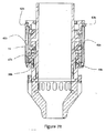
- the seal lubricant passageways 42a are in fluid communication with seal interface 30a, and similarly in Fig. 7B , lubricant passageways 42b are in fluid communication with seal interface 30b.
- the bearing lubricant passageways 23 are provided with an inlet port 60 and an outlet port 61 while the seal lubricant passageways 42a, 42b are provided with an inlet port 62a, 62b and an outlet port 63a, 63b to enable independent flows of the bearing and seal lubricants.
- the inlet and outlet ports for the bearing lubricant and seal lubricant can be from a top of the bearing pack 20.
- Seal lubricant passageways 42a, 42b for each seal interface 30a, 30b are in fluid communication with their own corresponding connecting passageway 47a, 47b ( Figs. 7A and 7B ), allowing for independent control over each seal interface 30a, 30b.
- the bearing lubricant passageway 23 is in fluid communication with bearing interface 32 via a bearing connecting passageway 25.
- the bearing lubricant passageway 23 is in fluid communication with a corresponding inlet port 60 and a corresponding outlet port 61, forming a discrete fluid system that is independent of other fluid systems.
- lubricant passageway 42a in fluid communication with seal interface 30a via the connecting passageway 47a, is in fluid communication with its corresponding inlet port 62a and outlet port 63a, forming another discrete and independent fluid system.
- Fig. 7B illustrates another discrete and independent fluid system with lubricant passageway way 42b in fluid communication with seal interface 30b via connecting passageway 47b. Similar to the above fluid systems, lubricant passageway 42b is also in fluid communication with a corresponding inlet port 62b and outlet port 63b.
- the lubricant passageways 42a, 42b can be a common annular passageway, formed in the outer bearing housing, allowing for common control of the seal interfaces 30a, 30b.
- a seal lubricant is directed to each of the seal interfaces 30a, 30b at a pressure that is appropriate for the operational conditions observed for that particular wellhead operations.
- the seal lubricant can be charged to an appropriate pressure, which can be greater than or lower than the pressure of the wellbore fluids.
- the seal lubricant under pressure can be used to monitor seal integrity.
- the seal lubricant can be continuously or periodically flushed within the seal interfaces 30a, 30b.
- a pump can be fluidly connect corresponding inlets and outlets to a seal lubricant reservoir. If continuous flushing is not necessary, and periodic flushing of the seal lubricant is sufficient, displacement of the used seal lubricant can be accomplished with a simple hand pump to provide sufficient force to eject used lubricant and inject fresh lubricant to the seal interfaces 30a, 30b. For these purposes, a single port can be used to both introduce clean seal lubricant and release used seal lubricant.
- a circulation pump can be operatively connected to the corresponding inlet and outlet of the bearing elements 21 a, 21 b, 21 c to form a closed loop circulation system for continuously flowing lubricant through the bearing elements 21 a, 21 b, 21c.
- the flowing lubricant cools and lubricates the bearing elements 21a, 21b, 21c. Cooling of the bearing elements 21 a, 21 b, 21c provides a general cooling effect to the surrounding structure which is beneficial to other components such as the sealing elements 41 a, 41b, 41c.
- the independency of the bearing and seal interfaces with each other and the independency of their corresponding lubricant passageway allows for differing conditions to be maintained across each interface, allowing for an operator to select the optimal levels of lubricant pressure across each sealing element and the circulating rate of the lubricant for each seal interface to achieve longer sealing element life.
- the stationary housing 2 can be adapted to include a water jacket to aid in cooling the bearing pack 20.
- an exemplary sealing element is an elastomeric seal, such as a two part, U-cup seal, designed by the Applicant and commissioned for manufacture by SKF USA.
- Each sealing element 41a, 41 b, 41 c, 81 a 81 b remains stationary, supported in the outer bearing housing 15 by corresponding seal carriers 43a, 43b, 43c, 83a, 83b which are in turn supported by the stationary housing 2 while maintaining a seal against the quill shaft 13.
- this two part multi-lip seal used for seal elements 41a, 41b, 41c, 81a, and 81b comprises a body 150 and a loading ring 151.
- the body 150 comprises an outer peripheral wall 155, having a flange 152, an annular cavity 156, and an inner sealing surface 153 adapted to engage the quill shaft 13.
- the outer peripheral wall 155 is supported in the outer bearing housing 15.
- the flange 152 having a one-half of a dovetail profile, is tapered radially, its distal end 152a having a greater axial depth than its proximal end 152b.
- the inner sealing surface 153 illustrated for sealing against the quill shaft 13 comprises a lower sealing surface 153a, an upper sealing surface 153b and a sealing channel 153c therebetween.
- the sealing channel 153c provides an area to capture and retain any debris that can result from wearing of the lower sealing surface 153a. The captured debris will be isolated within the sealing channel 153c and will not interfere with the upper sealing surface 153b, prolonging the life of the upper sealing surface 153b, and thus increasing the life expectancy of the sealing element.
- the loading ring 151 has a greater cross-sectional width than that of the annular cavity 156.
- the loading ring 151 fits within the annular cavity 156, applying a radial force to urge the inner sealing surface 153 to expand radially inwardly to sealingly engage the quill shaft 13.
- the loading ring 151 provides a radially inwardly force against the inner sealing surface 153 urging the inner sealing surface 153 to displace radially inwardly.
- the body 150 can be composed of carbon fibre filled modified polytetrafluoroethylene (PTFE).
- the loading ring 151 can be of a springy metallic material, such as hardened cobalt-chromium-nickel alloy, more commonly known as elgiloy.
- the loading ring 151 provides a consistent radially inwardly force sufficient to urge the inner sealing surface 153 of the body 150 to seal against the quill shaft 13 while prolonging the life of the sealing element.
- a sealing element is supported by a seal carrier 95.
- the inner sealing surface 153 of the sealing element engages the quill shaft 13.
- the seal carrier 95 is profiled to fit the sealing element and comprises an interface surface 154, a complementary radially tapered surface 160 and a back wall 161.
- the flange 152 is supported on the complementary radially tapered surface 160.
- a seal gland 157 is formed between the distal end 152a of the flange 152 and the back wall 161.
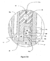
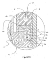
- the sealing element is actuable between a non-activated state and an activated state. As shown in Fig. 11A , when there is no axial compression exerting a force F on the sealing element, the sealing element is in its non-activated state. In its non-activated state, flange 152 is relaxed and has a radial extent R that does not distend into the seal gland 157.
- flange 152 when there is an axial compressive force F exerted, flange 152 radially distends, urging distal end 152a radially outward towards the back wall 161 of the seal carrier 95 and into the seal gland 157.
- the radial extent R' of flange 152, when the sealing element is activated, is greater than the radial extent R when the sealing element is not activated.
- the Applicant believes that the axial compression of the sealing element, causes the radially outwardly distention of the flange 152 and does not cause the radial inward movement of the inner sealing surface 153. This radially outwardly movement of the flange 152 firmly secures the sealing element within the bearing pack 20 and at the same time does not increase the rotational drag exerted on the quill shaft 13. The Applicant believes that by allowing the flange 152 to distend radially outwardly, the inner sealing surface 153 is not crushed against the quill shaft 13 and does not contribute to rotational drag.
- the Applicant believes that the radially outwardly distention of the flange 152 allows for proper activation of the sealing element under pressure and in zero pressure environments, resulting in lower break torque limits and running torque, of the quill shaft 13, and thus ensuring increased longevity of the sealing elements 41a, 41b, 41c, 81a, 81b.
- a seal interface pressure monitor (not shown) can be used to monitor the pressure at each of the seal interfaces 30a, 30b. With each successive failure of the sealing elements 41a, 41b, a corresponding increase in fluid pressure at the seal interfaces 30a, 30b should be observed, allowing an operator to identify each sealing element that has failed, and preemptively replace the bearing pack 20 before the failure of the last sealing element 41c and the introduction of wellbore fluids into the bearings 21, resulting in NPT.
- the stationary housing in operation, underneath the rotary table of a drilling rig, the stationary housing is secured to a wellhead or a BOP stack above a wellhead.
- the bearing pack Above the rotary table and the drilling rig floor, the bearing pack is positioned on an intervening tubular of a tubing string.
- the intervening tubular with the bearing pack is lowered through a working bore of the rotary table and positioned within the assembly bore of the stationary housing.
- the bearing pack is then secured within the assembly bore by a retainer plate, such as a threaded screw cap or a thrust plate. Securing the retainer plate can involve simply tightening down the threaded screw cap, or can involve actuating a plurality of lag bolts circumferentially spaced along a top portion of the stationary housing, to engage the thrust plate.
Landscapes
- Life Sciences & Earth Sciences (AREA)
- Engineering & Computer Science (AREA)
- Geology (AREA)
- Mining & Mineral Resources (AREA)
- Physics & Mathematics (AREA)
- Environmental & Geological Engineering (AREA)
- Fluid Mechanics (AREA)
- General Life Sciences & Earth Sciences (AREA)
- Geochemistry & Mineralogy (AREA)
- Sealing Devices (AREA)
Claims (15)
- Geschmierter modularer Lagerblock für eine Drehsteuervorrichtung, wobei der geschmierte modulare Lagerblock für das Abdichten von Lagern gegen Bohrlochfluide in einem Bohrloch eingerichtet ist, wobei der geschmierte modulare Lagerblock Folgendes umfasst:ein Lagerblockgehäuse (15) und eine drehbare zylindrische Hülse (13), die zum Hindurchführen von Rohren eingerichtet sind und zwischen sich einen ringförmigen Montageraum bilden,Lagerelemente (21a, 21b, 21c, 21d), die in dem ringförmigen Montageraum angeordnet sind, zum radialen und axialen Stützen der drehbaren zylindrischen Hülse (13) innerhalb des Lagerblockgehäuses (15), und gekennzeichnet durcheine oder mehrere Dichtungsbaugruppen (40), wobei jede der einen oder der mehreren Dichtungsbaugruppen (40) mindestens ein Dichtungselement (41a, 41b, 41c) aufweist, wobei jedes des mindestens einen Dichtungselements (41a, 41b, 41c) ferner Folgendes umfasst:einen elastomeren Körper, der zwischen einem ersten, nichtaktivierten Zustand und einem zweiten, aktivierten Zustand betätigbar ist, wobei der elastomere Körper Folgendes aufweist:einen ringförmigen Hohlraum,eine innere Dichtungsfläche, die zum Eingriff mit der drehbaren zylindrischen Hülse (13) eingerichtet ist, undeinen radial auswärts verlaufenden Flansch, der in dem Lagerblockgehäuse (15) gestützt wird, undeinen Ladering, der in den ringförmigen Hohlraum eingepasst ist, zum Drücken der inneren Dichtfläche derart, dass sie sich radial einwärts ausdehnt, um in Eingriff mit der drehbaren zylindrischen Hülse zwecks Abdichten an derselben zu kommen, wobei, wenn sich der elastomere Körper im ersten, nichtaktivierten Zustand befindet, der radial auswärts verlaufende Flansch eine erste radiale Erstreckung aufweist, die geringer als die radiale Erstreckung eines Lagermontageraums ist, undwobei, wenn sich der elastomere Körper im zweiten, aktivierten Zustand befindet, der radial auswärts verlaufende Flansch axial komprimiert ist, sich radial zum Lagerblockgehäuse hin dehnt und eine zweite radiale Erstreckung aufweist, die größer als die erste radiale Erstreckung ist, undein elastomeres Abstreiferelement zum Abdichten der Rohre gegen das Vorbeiführen von Bohrlochfluiden.
- Geschmierter modularer Lagerblock nach Anspruch 1, wobei die Lagerelemente (21a, 21b, 21c, 21d) ein Paar aus Radiallagern mit axialem Spiel und ein Paar aus Axiallagern mit radialem Spiel sind.
- Geschmierter modularer Lagerblock nach Anspruch 1 oder 2, wobei die eine oder die mehreren Dichtungsbaugruppen (40) ferner eine obere Dichtungsbaugruppe oberhalb der Lagerelemente und eine untere Dichtungsbaugruppe unterhalb der Lagerelemente umfassen.
- Geschmierter modularer Lagerblock nach Anspruch 3, wobei die drehbare zylindrische Hülse (13) ferner mindestens eine obere, auswechselbare Verschleißhülse, die an die obere Dichtungsbaugruppe angrenzt, und mindestens eine untere, auswechselbare Verschleißhülse, die an die untere Dichtungsbaugruppe angrenzt, umfasst.
- Geschmierter modularer Lagerblock nach Anspruch 3 oder 4, wobei die obere Dichtungsbaugruppe ferner mindestens ein oberes Dichtungselement umfasst und die untere Dichtungsbaugruppe ferner mindestens zwei untere Dichtungselemente umfasst.
- Geschmierter modularer Lagerblock nach Anspruch 5, wobei die Lagerelemente (21a, 21b, 21c, 21d) einen Lagerelement-Schmierstoff unter Druck aufweisen und die mindestens zwei unteren Dichtungselemente ferner mindestens ein bidirektionales Dichtungselement umfassen, das so ausgerichtet ist, dass es gegen das Austreten des Lagerelement-Schmierstoffs unter Druck nach unten in das Bohrloch abdichtet.
- Geschmierter modularer Lagerblock nach einem der vorhergehenden Ansprüche, wobei das mindestens eine Dichtungselement (40) ferner mindestens eine erste Dichtungsfläche, eine zweite Dichtungsfläche und eine umlaufende Kerbe dazwischen umfasst.
- Geschmierter modularer Lagerblock nach einem der vorhergehenden Ansprüche, wobei das mindestens eine Dichtungselement (40) mindestens zwei Dichtungselemente mit mindestens einer Dichtungsgrenzfläche zwischen ihnen sind und wobei ein zweiter Dichtungsgrenzflächen-Schmierstoff für die mindestens eine Dichtungsgrenzfläche durch mindestens einen Schmierstoff-Durchgang in Fluidverbindung zwischen dem Lagergehäuse und jeder der mindestens einen Dichtungsgrenzflächen bereitgestellt ist.
- Geschmierter modularer Lagerblock nach einem der vorhergehenden Ansprüche, wobei der radial auswärts verlaufende Flansch eine axiale Tiefe aufweist, die an einem distalen Ende größer als an einem proximalen Ende ist, und von einem entsprechend profilierten Lagerblockgehäuse gestützt wird.
- Drehsteuervornchtung, die für einen Bohrlochkopf eingerichtet ist, umfassend:ein ortsfestes Gehäuse (15) mit einer Öffnung und gekennzeichnet durch den geschmierten modularen Lagerblock (20) nach einem der Ansprüche 1 bis 9, der in die Öffnung eingepasst ist, undeine Halteplatte (6), die in die Öffnung eingepasst und darin gesichert ist, zum Sichern des geschmierten modularen Lagerblocks (20) in der Öffnung des ortsfesten Gehäuses (15).
- Drehsteuervornchtung nach Anspruch 10, wobei die Halteplatte (6) in der Öffnung durch mehrere Ankerbolzen (55), die umlaufend um einen oberen Abschnitt des ortsfesten Gehäuses (15) beabstandet sind, gesichert ist, wobei die mehreren Ankerbolzen (55) Enden zum Eingriff mit entsprechenden dazu passenden Flächen der Halteplatte (6) aufweisen.
- Drehsteuervornchtung nach Anspruch 10 oder 11, wobei die Halteplatte (6) durch eine Arbeitsöffnung eines Drehtischs passt.
- Verfahren zum Abdichten von Rohren, die durch eine Arbeitsöffnung in einem Drehtisch hindurchgeführt werden und sich in ein Bohrloch hinein und aus diesem heraus bewegen, wobei das Verfahren durch folgende Schritte gekennzeichnet ist:Sichern eines Drehausbruchskopfs mit einer Montageöffnung an einem Bohrlochkopf unterhalb des Drehtischs,Positionieren eines geschmierten modularen Lagerblocks (20) um ein Rohr,Absenken des Rohrs und des geschmierten Lagerblocks durch die Arbeitsöffnung des Drehtischs,Positionieren des Rohrs und des geschmierten Lagerblocks in der Montageöffnung des Drehausbruchskopfs,Sichern des geschmierten Lagerblocks (20) in der Montageöffnung des Drehausbruchskopfs, wobei das Sichern des geschmierten Lagerblocks das Positionieren einer Halteplatte (6) um das Rohr umfasst.
- Verfahren nach Anspruch 13, wobei das Sichern des geschmierten Lagerblocks ferner Folgendes umfasst:Absenken der Halteplatte (6) durch die Arbeitsöffnung des Drehtischs, um den Drehausbruchskopf in der Montageöffnung in Eingriff zu nehmen, undBetätigen mehrerer Ankerschrauben (55) an einem oberen Abschnitt des Drehausbruchskopfs, um die Halteplatte (6) in dem Drehausbruchskopf zu sichern.
- Verfahren nach Anspruch 13, wobei das Positionieren einer Halteplatte (6) um das Rohr das Montieren einer mehrteiligen Halteplatte (6) um das Rohr umfasst, und
wobei das Sichern des geschmierten Lagerblocks (20) ferner Folgendes umfasst:In-Eingriff-Bringen der montierten mehrteiligen Halteplatte (6) mit dem Drehausbruchskopf in der Montageöffnung undBetätigen mehrerer Ankerschrauben (55) an einem oberen Abschnitt des Drehausbruchskopfs, um die Halteplatte (6) in dem Drehausbruchskopf zu sichern.
Applications Claiming Priority (1)
| Application Number | Priority Date | Filing Date | Title |
|---|---|---|---|
| PCT/CA2009/000835 WO2010144989A1 (en) | 2009-06-19 | 2009-06-19 | A universal rotating flow head having a modular lubricated bearing pack |
Publications (3)
| Publication Number | Publication Date |
|---|---|
| EP2443312A1 EP2443312A1 (de) | 2012-04-25 |
| EP2443312A4 EP2443312A4 (de) | 2014-04-30 |
| EP2443312B1 true EP2443312B1 (de) | 2015-07-22 |
Family
ID=43355627
Family Applications (1)
| Application Number | Title | Priority Date | Filing Date |
|---|---|---|---|
| EP09845956.3A Active EP2443312B1 (de) | 2009-06-19 | 2009-06-19 | Universeller drehausbruchskopf mit geschmiertem modualrem lagerblock |
Country Status (5)
| Country | Link |
|---|---|
| US (1) | US9284811B2 (de) |
| EP (1) | EP2443312B1 (de) |
| BR (1) | BRPI0925094B1 (de) |
| CA (1) | CA2765724C (de) |
| WO (1) | WO2010144989A1 (de) |
Families Citing this family (27)
| Publication number | Priority date | Publication date | Assignee | Title |
|---|---|---|---|---|
| US8573294B2 (en) | 2009-07-31 | 2013-11-05 | Schlumberger Technology Corporation | Cable bypass and method for controlled entry of a tubing string and a cable adjacent thereto |
| MX355820B (es) | 2010-10-05 | 2018-05-02 | Smith International | Método y aparato para la perforación con presión controlada. |
| CA2892930A1 (en) * | 2012-12-31 | 2014-07-03 | Halliburton Energy Services, Inc. | Electronically monitoring drilling conditions of a rotating control device during drilling operations |
| BR112015019224A2 (pt) * | 2013-02-11 | 2017-07-18 | Schlumberger Technology Bv | aparelho, e método |
| US9822628B2 (en) | 2013-10-23 | 2017-11-21 | Halliburton Energy Services, Inc. | Sealing element wear detection for wellbore devices |
| GB2547365A (en) * | 2014-11-06 | 2017-08-16 | Schlumberger Technology Bv | Cooling of rotating control device |
| US10066664B2 (en) * | 2015-08-18 | 2018-09-04 | Black Gold Rental Tools, Inc. | Rotating pressure control head system and method of use |
| GB201602949D0 (en) * | 2016-02-19 | 2016-04-06 | Oil States Ind Uk Ltd | Packer |
| BR112020011247B1 (pt) * | 2017-12-12 | 2023-11-14 | Ameriforge Group Inc | Método para monitoramento de condição de vedação para um sistema de vedação anular |
| CA3091991A1 (en) * | 2018-05-02 | 2019-11-07 | Ameriforge Group Inc. | Improved rotating control device for jackup rigs |
| EP3867490B1 (de) | 2018-10-19 | 2024-01-24 | Grant Prideco, Inc. | Ringdichtungssystem und integrierte bohrsteigrohrverbindung mit druckmanagement |
| CA3118413A1 (en) | 2018-11-02 | 2020-05-07 | Ameriforge Group Inc. | Static annular sealing systems and integrated managed pressure drilling riser joints for harsh environments |
| GB2580718B (en) * | 2019-01-17 | 2023-02-08 | Ntdrill Holdings Llc | Rotating control device with multiple seal cartridge |
| JP7442178B2 (ja) * | 2020-04-09 | 2024-03-04 | 鉱研工業株式会社 | ロッドチャック装置 |
| US11401771B2 (en) | 2020-04-21 | 2022-08-02 | Schlumberger Technology Corporation | Rotating control device systems and methods |
| US11187056B1 (en) | 2020-05-11 | 2021-11-30 | Schlumberger Technology Corporation | Rotating control device system |
| US11274517B2 (en) | 2020-05-28 | 2022-03-15 | Schlumberger Technology Corporation | Rotating control device system with rams |
| CN111472759B (zh) * | 2020-06-02 | 2024-09-20 | 东营市创世石油测试新技术开发有限责任公司 | 注水井测调仪输出轴高压动密封装置 |
| US11732543B2 (en) | 2020-08-25 | 2023-08-22 | Schlumberger Technology Corporation | Rotating control device systems and methods |
| US11434714B2 (en) | 2021-01-04 | 2022-09-06 | Saudi Arabian Oil Company | Adjustable seal for sealing a fluid flow at a wellhead |
| US11808111B2 (en) | 2022-02-11 | 2023-11-07 | Weatherford Technology Holdings, Llc | Rotating control device with integrated cooling for sealed bearings |
| WO2024118322A1 (en) * | 2022-12-02 | 2024-06-06 | Schlumberger Technology Corporation | Active rotating control device methodology and system |
| WO2025240812A1 (en) * | 2024-05-17 | 2025-11-20 | Schlumberger Technology Corporation | Rotating control device rotary seal |
| US12590503B2 (en) | 2024-05-30 | 2026-03-31 | Schlumberger Technology Corporation | Wellbore balanced pressure compensation for rotating control device (RCD) rotary seals |
| WO2025259748A1 (en) * | 2024-06-14 | 2025-12-18 | Schlumberger Technology Corporation | Self-contained pressure compensation for rotating control device seals |
| US12442267B1 (en) | 2024-07-29 | 2025-10-14 | Schlumberger Technology Corporation | Control systems and methods for RCD active pressure compensation |
| CN120719949B (zh) * | 2025-08-29 | 2025-11-04 | 招远金河石油设备技术开发有限公司 | 用于石油开采的井下充填工具 |
Family Cites Families (11)
| Publication number | Priority date | Publication date | Assignee | Title |
|---|---|---|---|---|
| US4157186A (en) * | 1977-10-17 | 1979-06-05 | Murray Donnie L | Heavy duty rotating blowout preventor |
| US4154448A (en) | 1977-10-18 | 1979-05-15 | Biffle Morris S | Rotating blowout preventor with rigid washpipe |
| US4304310A (en) * | 1979-08-24 | 1981-12-08 | Smith International, Inc. | Drilling head |
| US4363357A (en) | 1980-10-09 | 1982-12-14 | Hunter Joseph M | Rotary drilling head |
| US5647444A (en) | 1992-09-18 | 1997-07-15 | Williams; John R. | Rotating blowout preventor |
| US5662181A (en) | 1992-09-30 | 1997-09-02 | Williams; John R. | Rotating blowout preventer |
| US6244359B1 (en) | 1998-04-06 | 2001-06-12 | Abb Vetco Gray, Inc. | Subsea diverter and rotating drilling head |
| US6725951B2 (en) * | 2001-09-27 | 2004-04-27 | Diamond Rotating Heads, Inc. | Erosion resistent drilling head assembly |
| US7040394B2 (en) * | 2002-10-31 | 2006-05-09 | Weatherford/Lamb, Inc. | Active/passive seal rotating control head |
| US7699109B2 (en) | 2006-11-06 | 2010-04-20 | Smith International | Rotating control device apparatus and method |
| CA2634937C (en) * | 2007-12-21 | 2015-03-31 | Optimal Pressure Drilling Services Inc. | Seal cleaning and lubricating bearing assembly for a rotating flow diverter |
-
2009
- 2009-06-19 EP EP09845956.3A patent/EP2443312B1/de active Active
- 2009-06-19 BR BRPI0925094-8A patent/BRPI0925094B1/pt active IP Right Grant
- 2009-06-19 CA CA2765724A patent/CA2765724C/en active Active
- 2009-06-19 US US13/378,957 patent/US9284811B2/en active Active
- 2009-06-19 WO PCT/CA2009/000835 patent/WO2010144989A1/en not_active Ceased
Also Published As
| Publication number | Publication date |
|---|---|
| EP2443312A1 (de) | 2012-04-25 |
| US9284811B2 (en) | 2016-03-15 |
| EP2443312A4 (de) | 2014-04-30 |
| US20120217022A1 (en) | 2012-08-30 |
| BRPI0925094B1 (pt) | 2019-04-09 |
| CA2765724C (en) | 2017-01-10 |
| CA2765724A1 (en) | 2010-12-23 |
| WO2010144989A1 (en) | 2010-12-23 |
Similar Documents
| Publication | Publication Date | Title |
|---|---|---|
| EP2443312B1 (de) | Universeller drehausbruchskopf mit geschmiertem modualrem lagerblock | |
| CA2634937C (en) | Seal cleaning and lubricating bearing assembly for a rotating flow diverter | |
| US6354385B1 (en) | Rotary drilling head assembly | |
| EP1274920B1 (de) | Rotierendes ausbruchsverhütungsventil für hohen druck | |
| EP2689098B1 (de) | Dichtungsanordnung | |
| US10066664B2 (en) | Rotating pressure control head system and method of use | |
| US11236575B2 (en) | Rotating control device with multiple seal cartridge | |
| US20120055677A1 (en) | Rotating flow control diverter with riser pipe adapter | |
| CA2888307C (en) | Redundant seal apparatus and method | |
| EP2529077B1 (de) | Unterwasserstopfbuchse und verfahren zum betrieb eines bohrstrangs durch die stopfbuchse | |
| CA2711206C (en) | Stuffing box for progressing cavity pump drive | |
| US9267350B1 (en) | Top pot assembly | |
| EP3867490A1 (de) | Ringdichtungssystem und integrierte bohrsteigrohrverbindung mit druckmanagement | |
| US20130233556A1 (en) | Rotating flow control diverter | |
| US11136848B2 (en) | Rotating control device with cooling mandrel | |
| CA3111310A1 (en) | Rotating control device seal | |
| US11702901B1 (en) | Top pot assembly | |
| US10392891B1 (en) | Top pot assembly | |
| WO2023147409A1 (en) | Sealed rotating system for managed pressure drilling | |
| US20070007002A1 (en) | Washpipe seal | |
| WO2013055225A1 (en) | System for active sealing of a drill string | |
| CA2508625A1 (en) | Rotating flow diverter |
Legal Events
| Date | Code | Title | Description |
|---|---|---|---|
| PUAI | Public reference made under article 153(3) epc to a published international application that has entered the european phase |
Free format text: ORIGINAL CODE: 0009012 |
|
| 17P | Request for examination filed |
Effective date: 20120104 |
|
| AK | Designated contracting states |
Kind code of ref document: A1 Designated state(s): AT BE BG CH CY CZ DE DK EE ES FI FR GB GR HR HU IE IS IT LI LT LU LV MC MK MT NL NO PL PT RO SE SI SK TR |
|
| DAX | Request for extension of the european patent (deleted) | ||
| A4 | Supplementary search report drawn up and despatched |
Effective date: 20140331 |
|
| RIC1 | Information provided on ipc code assigned before grant |
Ipc: E21B 33/08 20060101ALI20140325BHEP Ipc: F16C 33/72 20060101ALI20140325BHEP Ipc: E21B 33/02 20060101AFI20140325BHEP |
|
| GRAP | Despatch of communication of intention to grant a patent |
Free format text: ORIGINAL CODE: EPIDOSNIGR1 |
|
| INTG | Intention to grant announced |
Effective date: 20150123 |
|
| GRAS | Grant fee paid |
Free format text: ORIGINAL CODE: EPIDOSNIGR3 |
|
| GRAA | (expected) grant |
Free format text: ORIGINAL CODE: 0009210 |
|
| AK | Designated contracting states |
Kind code of ref document: B1 Designated state(s): AT BE BG CH CY CZ DE DK EE ES FI FR GB GR HR HU IE IS IT LI LT LU LV MC MK MT NL NO PL PT RO SE SI SK TR |
|
| REG | Reference to a national code |
Ref country code: GB Ref legal event code: FG4D |
|
| REG | Reference to a national code |
Ref country code: CH Ref legal event code: EP |
|
| REG | Reference to a national code |
Ref country code: IE Ref legal event code: FG4D |
|
| REG | Reference to a national code |
Ref country code: AT Ref legal event code: REF Ref document number: 738051 Country of ref document: AT Kind code of ref document: T Effective date: 20150815 |
|
| REG | Reference to a national code |
Ref country code: DE Ref legal event code: R096 Ref document number: 602009032423 Country of ref document: DE |
|
| REG | Reference to a national code |
Ref country code: AT Ref legal event code: MK05 Ref document number: 738051 Country of ref document: AT Kind code of ref document: T Effective date: 20150722 |
|
| REG | Reference to a national code |
Ref country code: NO Ref legal event code: T2 Effective date: 20150722 Ref country code: LT Ref legal event code: MG4D |
|
| REG | Reference to a national code |
Ref country code: NL Ref legal event code: MP Effective date: 20150722 |
|
| PG25 | Lapsed in a contracting state [announced via postgrant information from national office to epo] |
Ref country code: LV Free format text: LAPSE BECAUSE OF FAILURE TO SUBMIT A TRANSLATION OF THE DESCRIPTION OR TO PAY THE FEE WITHIN THE PRESCRIBED TIME-LIMIT Effective date: 20150722 Ref country code: FI Free format text: LAPSE BECAUSE OF FAILURE TO SUBMIT A TRANSLATION OF THE DESCRIPTION OR TO PAY THE FEE WITHIN THE PRESCRIBED TIME-LIMIT Effective date: 20150722 Ref country code: GR Free format text: LAPSE BECAUSE OF FAILURE TO SUBMIT A TRANSLATION OF THE DESCRIPTION OR TO PAY THE FEE WITHIN THE PRESCRIBED TIME-LIMIT Effective date: 20151023 Ref country code: LT Free format text: LAPSE BECAUSE OF FAILURE TO SUBMIT A TRANSLATION OF THE DESCRIPTION OR TO PAY THE FEE WITHIN THE PRESCRIBED TIME-LIMIT Effective date: 20150722 |
|
| PG25 | Lapsed in a contracting state [announced via postgrant information from national office to epo] |
Ref country code: PT Free format text: LAPSE BECAUSE OF FAILURE TO SUBMIT A TRANSLATION OF THE DESCRIPTION OR TO PAY THE FEE WITHIN THE PRESCRIBED TIME-LIMIT Effective date: 20151123 Ref country code: SE Free format text: LAPSE BECAUSE OF FAILURE TO SUBMIT A TRANSLATION OF THE DESCRIPTION OR TO PAY THE FEE WITHIN THE PRESCRIBED TIME-LIMIT Effective date: 20150722 Ref country code: HR Free format text: LAPSE BECAUSE OF FAILURE TO SUBMIT A TRANSLATION OF THE DESCRIPTION OR TO PAY THE FEE WITHIN THE PRESCRIBED TIME-LIMIT Effective date: 20150722 Ref country code: PL Free format text: LAPSE BECAUSE OF FAILURE TO SUBMIT A TRANSLATION OF THE DESCRIPTION OR TO PAY THE FEE WITHIN THE PRESCRIBED TIME-LIMIT Effective date: 20150722 Ref country code: AT Free format text: LAPSE BECAUSE OF FAILURE TO SUBMIT A TRANSLATION OF THE DESCRIPTION OR TO PAY THE FEE WITHIN THE PRESCRIBED TIME-LIMIT Effective date: 20150722 Ref country code: IS Free format text: LAPSE BECAUSE OF FAILURE TO SUBMIT A TRANSLATION OF THE DESCRIPTION OR TO PAY THE FEE WITHIN THE PRESCRIBED TIME-LIMIT Effective date: 20151122 Ref country code: ES Free format text: LAPSE BECAUSE OF FAILURE TO SUBMIT A TRANSLATION OF THE DESCRIPTION OR TO PAY THE FEE WITHIN THE PRESCRIBED TIME-LIMIT Effective date: 20150722 |
|
| REG | Reference to a national code |
Ref country code: DE Ref legal event code: R097 Ref document number: 602009032423 Country of ref document: DE |
|
| PG25 | Lapsed in a contracting state [announced via postgrant information from national office to epo] |
Ref country code: DK Free format text: LAPSE BECAUSE OF FAILURE TO SUBMIT A TRANSLATION OF THE DESCRIPTION OR TO PAY THE FEE WITHIN THE PRESCRIBED TIME-LIMIT Effective date: 20150722 Ref country code: EE Free format text: LAPSE BECAUSE OF FAILURE TO SUBMIT A TRANSLATION OF THE DESCRIPTION OR TO PAY THE FEE WITHIN THE PRESCRIBED TIME-LIMIT Effective date: 20150722 Ref country code: SK Free format text: LAPSE BECAUSE OF FAILURE TO SUBMIT A TRANSLATION OF THE DESCRIPTION OR TO PAY THE FEE WITHIN THE PRESCRIBED TIME-LIMIT Effective date: 20150722 Ref country code: CZ Free format text: LAPSE BECAUSE OF FAILURE TO SUBMIT A TRANSLATION OF THE DESCRIPTION OR TO PAY THE FEE WITHIN THE PRESCRIBED TIME-LIMIT Effective date: 20150722 Ref country code: IT Free format text: LAPSE BECAUSE OF FAILURE TO SUBMIT A TRANSLATION OF THE DESCRIPTION OR TO PAY THE FEE WITHIN THE PRESCRIBED TIME-LIMIT Effective date: 20150722 |
|
| PLBE | No opposition filed within time limit |
Free format text: ORIGINAL CODE: 0009261 |
|
| STAA | Information on the status of an ep patent application or granted ep patent |
Free format text: STATUS: NO OPPOSITION FILED WITHIN TIME LIMIT |
|
| PG25 | Lapsed in a contracting state [announced via postgrant information from national office to epo] |
Ref country code: RO Free format text: LAPSE BECAUSE OF FAILURE TO SUBMIT A TRANSLATION OF THE DESCRIPTION OR TO PAY THE FEE WITHIN THE PRESCRIBED TIME-LIMIT Effective date: 20150722 |
|
| 26N | No opposition filed |
Effective date: 20160425 |
|
| PG25 | Lapsed in a contracting state [announced via postgrant information from national office to epo] |
Ref country code: SI Free format text: LAPSE BECAUSE OF FAILURE TO SUBMIT A TRANSLATION OF THE DESCRIPTION OR TO PAY THE FEE WITHIN THE PRESCRIBED TIME-LIMIT Effective date: 20150722 |
|
| PG25 | Lapsed in a contracting state [announced via postgrant information from national office to epo] |
Ref country code: BE Free format text: LAPSE BECAUSE OF FAILURE TO SUBMIT A TRANSLATION OF THE DESCRIPTION OR TO PAY THE FEE WITHIN THE PRESCRIBED TIME-LIMIT Effective date: 20150722 |
|
| REG | Reference to a national code |
Ref country code: DE Ref legal event code: R119 Ref document number: 602009032423 Country of ref document: DE |
|
| PG25 | Lapsed in a contracting state [announced via postgrant information from national office to epo] |
Ref country code: MC Free format text: LAPSE BECAUSE OF FAILURE TO SUBMIT A TRANSLATION OF THE DESCRIPTION OR TO PAY THE FEE WITHIN THE PRESCRIBED TIME-LIMIT Effective date: 20150722 |
|
| REG | Reference to a national code |
Ref country code: CH Ref legal event code: PL |
|
| REG | Reference to a national code |
Ref country code: IE Ref legal event code: MM4A |
|
| REG | Reference to a national code |
Ref country code: FR Ref legal event code: ST Effective date: 20170228 |
|
| PG25 | Lapsed in a contracting state [announced via postgrant information from national office to epo] |
Ref country code: DE Free format text: LAPSE BECAUSE OF NON-PAYMENT OF DUE FEES Effective date: 20170103 Ref country code: CH Free format text: LAPSE BECAUSE OF NON-PAYMENT OF DUE FEES Effective date: 20160630 Ref country code: LI Free format text: LAPSE BECAUSE OF NON-PAYMENT OF DUE FEES Effective date: 20160630 Ref country code: FR Free format text: LAPSE BECAUSE OF NON-PAYMENT OF DUE FEES Effective date: 20160630 |
|
| PG25 | Lapsed in a contracting state [announced via postgrant information from national office to epo] |
Ref country code: IE Free format text: LAPSE BECAUSE OF NON-PAYMENT OF DUE FEES Effective date: 20160619 |
|
| PG25 | Lapsed in a contracting state [announced via postgrant information from national office to epo] |
Ref country code: NL Free format text: LAPSE BECAUSE OF FAILURE TO SUBMIT A TRANSLATION OF THE DESCRIPTION OR TO PAY THE FEE WITHIN THE PRESCRIBED TIME-LIMIT Effective date: 20150722 |
|
| PG25 | Lapsed in a contracting state [announced via postgrant information from national office to epo] |
Ref country code: HU Free format text: LAPSE BECAUSE OF FAILURE TO SUBMIT A TRANSLATION OF THE DESCRIPTION OR TO PAY THE FEE WITHIN THE PRESCRIBED TIME-LIMIT; INVALID AB INITIO Effective date: 20090619 Ref country code: CY Free format text: LAPSE BECAUSE OF FAILURE TO SUBMIT A TRANSLATION OF THE DESCRIPTION OR TO PAY THE FEE WITHIN THE PRESCRIBED TIME-LIMIT Effective date: 20150722 |
|
| PG25 | Lapsed in a contracting state [announced via postgrant information from national office to epo] |
Ref country code: MT Free format text: LAPSE BECAUSE OF NON-PAYMENT OF DUE FEES Effective date: 20160630 Ref country code: TR Free format text: LAPSE BECAUSE OF FAILURE TO SUBMIT A TRANSLATION OF THE DESCRIPTION OR TO PAY THE FEE WITHIN THE PRESCRIBED TIME-LIMIT Effective date: 20150722 Ref country code: MK Free format text: LAPSE BECAUSE OF FAILURE TO SUBMIT A TRANSLATION OF THE DESCRIPTION OR TO PAY THE FEE WITHIN THE PRESCRIBED TIME-LIMIT Effective date: 20150722 Ref country code: LU Free format text: LAPSE BECAUSE OF NON-PAYMENT OF DUE FEES Effective date: 20160619 |
|
| PG25 | Lapsed in a contracting state [announced via postgrant information from national office to epo] |
Ref country code: BG Free format text: LAPSE BECAUSE OF FAILURE TO SUBMIT A TRANSLATION OF THE DESCRIPTION OR TO PAY THE FEE WITHIN THE PRESCRIBED TIME-LIMIT Effective date: 20150722 |
|
| P01 | Opt-out of the competence of the unified patent court (upc) registered |
Effective date: 20231208 |
|
| PGFP | Annual fee paid to national office [announced via postgrant information from national office to epo] |
Ref country code: GB Payment date: 20250401 Year of fee payment: 17 |
|
| PGFP | Annual fee paid to national office [announced via postgrant information from national office to epo] |
Ref country code: NO Payment date: 20250610 Year of fee payment: 17 |