EP2443373B1 - Elektromagnetventil - Google Patents
Elektromagnetventil Download PDFInfo
- Publication number
- EP2443373B1 EP2443373B1 EP10722056.8A EP10722056A EP2443373B1 EP 2443373 B1 EP2443373 B1 EP 2443373B1 EP 10722056 A EP10722056 A EP 10722056A EP 2443373 B1 EP2443373 B1 EP 2443373B1
- Authority
- EP
- European Patent Office
- Prior art keywords
- armature
- solenoid valve
- coil
- end position
- permanent magnet
- Prior art date
- Legal status (The legal status is an assumption and is not a legal conclusion. Google has not performed a legal analysis and makes no representation as to the accuracy of the status listed.)
- Not-in-force
Links
Images


Classifications
-
- F—MECHANICAL ENGINEERING; LIGHTING; HEATING; WEAPONS; BLASTING
- F16—ENGINEERING ELEMENTS AND UNITS; GENERAL MEASURES FOR PRODUCING AND MAINTAINING EFFECTIVE FUNCTIONING OF MACHINES OR INSTALLATIONS; THERMAL INSULATION IN GENERAL
- F16K—VALVES; TAPS; COCKS; ACTUATING-FLOATS; DEVICES FOR VENTING OR AERATING
- F16K31/00—Actuating devices; Operating means; Releasing devices
- F16K31/02—Actuating devices; Operating means; Releasing devices electric; magnetic
- F16K31/06—Actuating devices; Operating means; Releasing devices electric; magnetic using a magnet, e.g. diaphragm valves, cutting off by means of a liquid
- F16K31/08—Actuating devices; Operating means; Releasing devices electric; magnetic using a magnet, e.g. diaphragm valves, cutting off by means of a liquid using a permanent magnet
- F16K31/082—Actuating devices; Operating means; Releasing devices electric; magnetic using a magnet, e.g. diaphragm valves, cutting off by means of a liquid using a permanent magnet using a electromagnet and a permanent magnet
-
- F—MECHANICAL ENGINEERING; LIGHTING; HEATING; WEAPONS; BLASTING
- F16—ENGINEERING ELEMENTS AND UNITS; GENERAL MEASURES FOR PRODUCING AND MAINTAINING EFFECTIVE FUNCTIONING OF MACHINES OR INSTALLATIONS; THERMAL INSULATION IN GENERAL
- F16K—VALVES; TAPS; COCKS; ACTUATING-FLOATS; DEVICES FOR VENTING OR AERATING
- F16K37/00—Special means in or on valves or other cut-off apparatus for indicating or recording operation thereof, or for enabling an alarm to be given
- F16K37/0025—Electrical or magnetic means
- F16K37/0033—Electrical or magnetic means using a permanent magnet, e.g. in combination with a reed relays
-
- F—MECHANICAL ENGINEERING; LIGHTING; HEATING; WEAPONS; BLASTING
- F16—ENGINEERING ELEMENTS AND UNITS; GENERAL MEASURES FOR PRODUCING AND MAINTAINING EFFECTIVE FUNCTIONING OF MACHINES OR INSTALLATIONS; THERMAL INSULATION IN GENERAL
- F16K—VALVES; TAPS; COCKS; ACTUATING-FLOATS; DEVICES FOR VENTING OR AERATING
- F16K37/00—Special means in or on valves or other cut-off apparatus for indicating or recording operation thereof, or for enabling an alarm to be given
- F16K37/0025—Electrical or magnetic means
- F16K37/0041—Electrical or magnetic means for measuring valve parameters
-
- H—ELECTRICITY
- H01—ELECTRIC ELEMENTS
- H01F—MAGNETS; INDUCTANCES; TRANSFORMERS; SELECTION OF MATERIALS FOR THEIR MAGNETIC PROPERTIES
- H01F7/00—Magnets
- H01F7/06—Electromagnets; Actuators including electromagnets
- H01F7/08—Electromagnets; Actuators including electromagnets with armatures
- H01F7/16—Rectilinearly-movable armatures
- H01F7/1607—Armatures entering the winding
- H01F7/1615—Armatures or stationary parts of magnetic circuit having permanent magnet
Definitions
- the invention relates to a solenoid valve having at least one electromagnetic circuit, which is composed of a wound on a coil carrier coil, an armature, two cores and at least one magnetizable return means and at least one permanent magnet, wherein the armature between two end positions, which are formed by the cores , and at least indirectly acting on a valve closure member, wherein means are provided which fix the armature in the non-energized state, wherein energizing the coil causes movement of the armature in the first or second end position, wherein the coil and the at least one permanent magnet in axial direction to each other are arranged such that in the return device form two successive in the axial direction permanent magnetic circuits, whereby the armature is fixed in an end position in the de-energized state, wherein a control device is provided, via which the coil umpo lbar, wherein the polarity reversal of the coil causes a change of the current direction and thus a reversal of direction of the electromagnetic circuits. Furthermore, the invention
- solenoid valves are well known.
- the DE 10 2005 011 596 B4 describes, for example, a solenoid valve in which a spring exerts a force on the armature, which acts in the direction of the second end position and a permanent magnet exerts a force on the armature in the direction of the first end position.
- the armature should be in the non-energized state in a stable position between the first end position and the second end position.
- the so-called stable intermediate layer can be left in the event of unforeseen external influences, such as violent impacts and / or movements, whereby the anchor may possibly end up in an unwanted end position.
- the return means is essentially composed of two axially successive return plate parts or sections, the coil being arranged in the first return plate part or section and the at least one permanent magnet being arranged in the second return plate part or section, wherein the at least one permanent magnet is arranged on a soft iron part, on the inner part of which a bearing means for the armature is provided, wherein the bearing means is arranged on the inside of the coil support and on the inside of the soft iron part.
- the inventive method according to claim 6 is characterized in that two permanent magnetic circuits are formed by the permanent magnet in the feedback device, whereby the armature is fixed in the non-energized state in one of the two end positions.
- the at least one permanent magnet is magnetized in the radial direction.
- the end position, in which the armature is in the de-energized state can be stored in a memory device.
- This memory device may be provided in the control device.
- the storage device is provided in the solenoid valve.
- a further advantageous method provides that the respective end position of the armature is stored in a memory device.
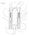
- FIG. 1 shows a schematically illustrated inventive solenoid valve 1, which acts in the present embodiment on a valve lifter 2, so, an unillustrated valve closure member can be opened or closed.
- Such a solenoid valve 1 could be used for example as a drive for a diverter valve.
- the electromagnetic valve 1 essentially has a coil 4 wound onto a coil carrier 3. Furthermore, a return device 5 is provided, which essentially consists of two return plate sections 6 and 7 in the present case. For assembly reasons, the return device 5 and in particular the return plate sections 6 and 7 are not made in one piece, but still have so-called discs 22, 23, wherein in the discs 22, 23, the cores 9 and 10 are arranged.
- At least one radically magnetized permanent magnet 11 is provided in the second return plate section 7, which in the present case is designed as a round magnet, but can also consist of several segments, and terminates in the axial direction against the coil 4.
- a running in the present embodiment as a DU socket bearing means 13 is disposed on the inside of the bobbin 3 and the inside of the soft iron part 12.
- an armature 14 is movably mounted, which is positively connected at its one end to the valve lifter 2.
- the armature 14 is basically movable between a first end position 15, which is formed by the first core 9, and a second end position 16, which is formed by the second core 10.
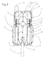
- FIG. 2 shows a schematic representation of a sectional view of the solenoid valve 1 according to the invention, in which the in the Return device by the permanent magnet 11 induced two successive in the axial direction of permanent magnetic circuits 18, 19 are located.
- the armature 14 is fixed in the respective end position 15, 16 by the action of the permanent-magnetic circuits 18, 19.
- this is, as shown, the first end position 15.
- This end position 15 can be stored in a known manner in the control unit 17, so that this specific position is stored in an engine control unit, so that no reference approach of the solenoid valve is necessary at the start of the engine.
- FIG. 3 shows now the electromagnet 1 with positive energization of the coil 4. It can be clearly seen how the electromagnetic circuits 20, 21 and the permanent magnetic circuits 18, 19 overlap. This leads in the present embodiment to the fact that when positive energization of the armature 15 is either moved to the first end position 15, or remains in this, depending on how the initial state was.
- FIG. 4 now shows the superposition of the electromagnetic 20, 21 and the permanent magnetic 18, 19 circles in negative energization of the coil 4.
- the negative energization ensures that the armature is moved to the second end position 16.
- the invention is not limited to the present embodiment. Insbesondre it is conceivable that no reversal of the coil is made and that the armature 14, for example, by a spring which is disposed between the core 9 and the armature 14, can be moved into the second end position 16. Also, the controller 17 may be disposed outside of the solenoid valve 1. Furthermore, the memory function does not necessarily have to be integrated in the control unit 17.
Landscapes
- Engineering & Computer Science (AREA)
- General Engineering & Computer Science (AREA)
- Mechanical Engineering (AREA)
- Physics & Mathematics (AREA)
- Electromagnetism (AREA)
- Power Engineering (AREA)
- Magnetically Actuated Valves (AREA)
- Electromagnets (AREA)
Description
- Die Erfindung betrifft ein Elektromagnetventil mit mindestens einem elektromagnetischen Kreis, der aus einer auf einen Spulenträger gewickelten Spule , einem Anker, zwei Kernen und mindestens einer magnetisierbaren Rückschlusseinrichtung aufgebaut ist und mindestens einem Permanentmagneten, wobei der Anker zwischen zwei Endlagen, die durch die Kerne ausgebildet sind, und zumindest indirekt auf ein Ventilverschlussglied einwirkt, wobei Mittel vorgesehen sind, die den Anker im nicht bestromten Zustand fixieren, wobei eine Bestromung der Spule eine Bewegung des Ankers in die erste oder die zweite Endlage verursacht, wobei die Spule und der mindestens eine Permanentmagnet in axialer Richtung zueinander derart angeordnet sind, dass in der Rückschlusseinrichtung sich zwei in axialer Richtung aufeinanderfolgende permanentmagnetische Kreise ausbilden, wodurch im unbestromten Zustand der Anker in einer Endlage fixiert ist, wobei eine Steuereinrichtung vorgesehen ist, über die die Spule umpolbar ist, wobei die Umpolung der Spule einen Wechsel der Stromrichtung und damit eine Richtungsumkehr der elektromagnetischen Kreise verursacht. Desweiteren betrifft die Erfindung ein Verfahren zur Steuerung eines derartigen Elektromagnetventils.
- Derartige Elektromagnetventile sind hinlänglich bekannt. Die
DE 10 2005 011 596 B4 beschreibt beispielsweise ein Elektromagnetventil, bei dem eine Feder eine Kraft auf den Anker ausübt, die in Richtung auf die zweite Endstellung wirkt und ein Permanentmagnet eine Kraft auf den Anker in die Richtung der ersten Endlage ausübt. Auf diese Weise soll sich der Anker im unbestromten Zustand in einer stabilen Lage zwischen der ersten Endlage und der zweiten Endlage befinden. Es sollte deutlich sein, dass die sogenannte stabile Zwischenlage bei unvorhergesehenen äußeren Einflüssen, wie heftigen Stößen und/oder Bewegungen verlassen werden kann, wodurch der Anker vielleicht in eine nicht gewollte Endlage gerät. - Aus der
US 4 797 645 A ist ein gattungsgemäßer elektromagnetischer Anker bekannt, der neben dem elektromagnetischen Kreises, einen Permanentmagneten und zwei die Endlage des Akers definierende Kerne aufweist, wobei die Umpolung eine Lageänderung den Anker auslöst. Jedoch erfolgt die Lageänderung noch sehr träge. - Es ist daher Aufgabe der Erfindung, ein Elektromagnetventil bereitzustellen, das die vorgenannten Nachteile vermeidet und mit einer möglichst geringen Bauteileanzahl auf günstige Weise herstellbar ist.
- Diese Aufgabe wird erfindungsgemäß nach Anspruch 1 dadurch gelöst, dass die Rückschlusseinrichtung im Wesentlichen aus zwei axial aufeinander folgenden Rückschlussblechteilen oder - abschnitten aufgebaut ist, wobei die Spule im ersten Rückschlussblechteil oder - abschnitt und der mindestens eine Permanentmagnet im zweiten Rückschlussblechteil oder -abschnitt angeordnet sind, wobei der mindestens eine Permanentmagnet auf einem Weicheisenteil angeordnet ist, auf dessen Innenteil ein Lagermittel für den Anker vorgesehen ist, wobei das Lagermittel auf der Innenseite des Spulenträgers und auf der Innenseite des Weicheisenteils angeordnet ist.
- Das erfindungsgemäße Verfahren nach Anspruch 6 zeichnet sich dadurch aus, dass durch den Permanentmagneten in der Rückschlusseinrichtung zwei permanentmagnetische Kreise ausgebildet werden, wodurch der Anker im nicht bestromten Zustand in einer der beiden Endlagen fixiert wird.
- Besonders vorteilhaft ist es, wenn der mindestens eine Permanentmagnet in radialer Richtung magnetisiert ist. In vorteilhafter Weise kann die Endlage, in der sich der Anker im unbestromten Zustand befindet, in einer Speichereinrichtung speicherbar sein. Diese Speichereinrichtung kann in der Steuereinrichtung vorgesehen sein.
- Auch ist es möglich, dass die Speichereinrichtung im Elektromagnetventil vorgesehen ist.
- Ein weiteres vorteilhaftes Verfahren sieht vor, dass die jeweilige Endlage des Ankers in einer Speichereinrichtung gespeichert wird.
- Eine Ausführungsform der Erfindung wird nachfolgend anhand der Zeichnung näher beschrieben, hierin zieigen:
- Figur 1
- eine schematische Schnittdarstellung eines erfindungsgemäßen Elektromagnetventils,
- Figur 2
- eine schematische Schnittdarstellung eines erfindungsgemäßen Elektromagnetventils im unbestromten Zustand mit Darstellung der permanentmagnetischen Kreise,
- Figur 3
- eine schematische Schnittdarstellung eines erfindungsgemäßen Elektromagnetventils bei positiver Bestromung, und
- Figur 4
- eine schematische Darstellung eines erfindungsgemäßen Elektromagnetventils bei negativer Bestromung.
-
Figur 1 zeigt ein schematisch dargestelltes erfindungsgemäßes Elektromagnetventil 1, das im vorliegenden Ausführungsbeispiel auf einen Ventilstößel 2 einwirkt, derart, dass ein nicht dargestelltes Ventilverschlussglied geöffnet oder verschlossen werden kann. - Ein derartiges Elektromagnetventil 1 könnte beispielsweise als Antrieb für ein Schubumluftventil eingesetzt werden.
- Im vorliegenden Ausführungsbeispiel weist das Elektromagnetventil 1 im Wesentlichen eine auf einen Spulenträger 3 gewickelte Spule 4 auf. Des Weiteren ist eine Rückschlusseinrichtung 5 vorgesehen, die im vorliegenden Fall im Wesentlichen aus zwei Rückschlussblechabschnitten 6 und 7 besteht. Aus montagetechnischen Gründen sind die Rückschlusseinrichtung 5 und insbesondere die Rückschlussblechabschnitte 6 und 7 nicht einteilig ausgeführt, sondern weisen noch sogenannte Scheiben 22, 23 auf, wobei in den Scheiben 22, 23 die Kerne 9 und 10 angeordnet sind.
- Im zweiten Rückschlussblechabschnitt 7 ist des Weiteren mindestens ein radikal magnetisierter Permanentmagnet 11 vorgesehen, der im vorliegenden Fall als Rundmagnet ausgeführt ist, aber auch aus mehreren Segmenten bestehen kann, und sich in Axialrichtung an die Spule 4 abschließt.
- Ein im vorliegenden Ausführungsbeispiel als DU-Buchse ausgeführte Lagermittel 13 ist auf der Innenseite des Spulenträgers 3 und der Innenseite des Weicheisenteil 12 angeordnet. In ihr ist ein Anker 14 beweglich gelagert, der an seinem einen Ende formschlüssig mit dem Ventilstößel 2 verbunden ist. Der Anker 14 ist grundsätzlich zwischen einer ersten Endlage 15, die durch den ersten Kern 9 gebildet wird, und einer zweiten Endlage 16, die durch den zweiten Kern 10 gebildet wird, bewegbar.
- Mit 17 ist lediglich schematisch eine Steuereinrichtung für das Elektromagnetventil 1 dargestellt, die im vorliegenden Ausführungsbeispiel auch als Speichereinrichtung dient.
-
Figur 2 zeigt in schematischer Darstellung eine Schnittansicht des erfindungsgemäßen Elektromagnetventils 1, bei dem die in der Rückschlusseinrichtung durch den Permanentmagneten 11 induzierten zwei in axialer Richtung aufeinander folgenden permanentmagnetischen Kreise 18, 19 eingezeichnet sind. Es sollte deutlich sein, dass durch die Wirkung der permanentmagnetischen Kreise 18, 19 der Anker 14 in der jeweiligen Endlage 15, 16 fixiert wird. In derFigur 2 ist dies, wie dargestellt, die erste Endlage 15. Diese Endlage 15 kann auf bekannte Weise im Steuergerät 17 gespeichert werden, so dass diese spezifische Stellung in einer Motorsteuereinheit hinterlegt ist, so dass beim Start des Motors keine Referenzanfahrt des Elektromagnetventils notwendig ist. -
Figur 3 zeigt nun den Elektromagneten 1 bei positiver Bestromung der Spule 4. Deutlich zu erkennen ist, wie sich die elektromagnetischen Kreise 20, 21 und die permanentmagnetischen Kreise 18, 19 überlagern. Dies führt in vorliegendem Ausführungsbeispiel dazu, dass bei positiver Bestromung der Anker 15 entweder in die erste Endlage 15 bewegt wird, oder in dieser verharrt, je nachdem, wie der Ausgangszustand war. -
Figur 4 zeigt nun die Überlagerung der elektromagnetischen 20, 21 und der permanentmagnetischen 18, 19 Kreise bei negativer Bestromung der Spule 4. Die negative Bestromung sorgt dafür, dass der Anker in die zweite Endlage 16 bewegt wird. - Es sollte deutlich sein, dass die Erfindung nicht auf das vorliegende Ausführungsbeispiel beschränkt ist. Insbesondre ist es denkbar, dass keine Umpolung der Spule vorgenommen wird und dass der Anker 14 beispielsweise durch eine Feder, die zwischen dem Kern 9 und dem Anker 14 angeordnet ist, in die zweite Endlage 16 bewegt werden kann. Auch kann das Steuergerät 17 außerhalb des Elektromagnetventils 1 angeordnet werden. Des Weiteren muss nicht zwangsläufig die Speicherfunktion im Steuergerät 17 integriert sein.
- Auch ist es möglich, dass z. B. der Kern 10 und die Scheibe 23 einteilig ausgeführt sind.
Claims (7)
- Elektromagnetventil mit mindestens einem elektromagnetischen Kreis, der aus einer auf einen Spulenträger (3) gewickelten Spule (4), einem Anker, (14) zwei Kernen (9, 10), mindestens einer magnetisierbaren Rückschlusseinrichtung (5) und mindestens einem Permanentmagneten (11) ausgebaut ist, wobei der Anker (14) zwischen zwei Endlagen (15, 16), die durch die Kerne (9, 10) ausgebildet sind, beweglicht gelagert ist, und zumindest indirekt auf ein Ventilverschlussglied (2) einwirkt, wobei Mittel vorgesehen sind, die den Anker im nicht bestromten Zustand fixieren, wobei eine Bestromung der Spule (4) eine Bewegung des Ankers (14) in die erste (15) oder die zweite Endlage (16) verursacht, wobei die Spule (4) und der mindestens eine Permanentmagnet (11) in axialer Richtung zueinander derart angeordnet sind, dass in der Rückschlusseinrichtung (5) sich zwei in axialer Richtung aufeinanderfolgende permanentmagnetische Kreise (18; 19) ausbilden, wodurch im unbestromten Zustand der Anker (14) in einer Endlage (15; 16) fixiert ist, wobei eine Steuereinrichtung (17) vorgesehen ist, über die die Spule (4) umpolbar ist, wobei die Umpolung der Spule (4) einen Wechsel der Stromrichtung und damit eine Richtungsumkehr der elektromagnetischen Kreise (20, 21) verursacht, dadurch gekennzeichnet, dass die Rückschlusseinrichtung (5) im Wesentlichen aus zwei axial aufeinander folgenden Rückschlussblechteilen oder -abschnitten (6, 7) aufgebaut ist, wobei die Spule (4) im ersten Rückschlussblechteil oder -abschnitt (6) und der mindestens eine Permanentmagnet (11) im zweiten Rückschlussblechteil oder -abschnitt (7) angeordnet ist, wobei der mindestens eine Permanentmagnet (11) auf einem Weicheisenteil (12) angeordnet ist, auf dessen Innenteil ein Lagermittel (13) für den Anker (14) vorgesehen ist, wobei das Lagermittel auf der Innenseite des Spulenträgers und auf der Innenseite des Weicheisenteils angeordnet ist.
- Elektromagnetventil nach Anspruch 1, dadurch gekennzeichnet, dass der mindestens eine Permanentmagnet (11) in radialer Richtung magnetisiert ist.
- Elektromagnetventil nach einem der vorhergehenden Ansprüche, dadurch gekennzeichnet, dass eine Speichereinrichtung vorgesehen ist, die die Endlage (15; 16), in der sich der Anker (14) im unbestromten Zustand befindet , speichert, wobei die Endlage in einer Motorsteuereinheit hinterlegbar ist, so dass beim Start eines Motors keine Referenzanfahrt des Elektromagnetventils notwendig ist.
- Elektromagnetventil nach Anspruch 3, dadurch gekennzeichnet, dass die Speichereinrichtung in der Steuereinrichtung (17) vorgesehen ist.
- Elektromagnetventil nach Anspruch 3 oder 4, dadurch gekennzeichnet, dass die Speichereinrichtung im Elektromagnetventil (1) vorgesehen ist.
- Verfahren zur Steuerung eines Elektromagnetventils nach Anspruch 1, wobei durch den Permanentmagneten (11) in der Rückschlusseinrichtung (5) zwei permanentmagnetische Kreise (18; 19) ausgebildet werden, wodurch der Anker (14) im nicht bestromten Zustand in einer der beiden Endlagen (15; 16) fixiert wird.
- Verfahren zur Steuerung eines Elektromagnetventils nach Anspruch 6, wobei eine Speichereinrichtung vorgesehen ist, wobei die jeweilige Endlage (15; 16) des Ankers (14) in der Speichereinrichtung gespeichert wird, welche Endlage in einer Motorsteuereinheit hinterlegbar ist, so dass beim Start eines Motors keine Referenzanfahrt des Elektromagnetventils notwendig ist.
Applications Claiming Priority (2)
| Application Number | Priority Date | Filing Date | Title |
|---|---|---|---|
| DE200910029826 DE102009029826B4 (de) | 2009-06-18 | 2009-06-18 | Elektromagnetventil |
| PCT/EP2010/056889 WO2010145906A1 (de) | 2009-06-18 | 2010-05-19 | Elektromagnetventil |
Publications (2)
| Publication Number | Publication Date |
|---|---|
| EP2443373A1 EP2443373A1 (de) | 2012-04-25 |
| EP2443373B1 true EP2443373B1 (de) | 2015-09-16 |
Family
ID=42831670
Family Applications (1)
| Application Number | Title | Priority Date | Filing Date |
|---|---|---|---|
| EP10722056.8A Not-in-force EP2443373B1 (de) | 2009-06-18 | 2010-05-19 | Elektromagnetventil |
Country Status (4)
| Country | Link |
|---|---|
| EP (1) | EP2443373B1 (de) |
| DE (1) | DE102009029826B4 (de) |
| ES (1) | ES2548991T3 (de) |
| WO (1) | WO2010145906A1 (de) |
Cited By (1)
| Publication number | Priority date | Publication date | Assignee | Title |
|---|---|---|---|---|
| US11248717B2 (en) | 2019-06-28 | 2022-02-15 | Automatic Switch Company | Modular smart solenoid valve |
Families Citing this family (4)
| Publication number | Priority date | Publication date | Assignee | Title |
|---|---|---|---|---|
| DE102009043722A1 (de) * | 2009-10-01 | 2011-04-07 | Pierburg Gmbh | Aktuator für eine Verbrennungskraftmaschine |
| CN115405165B (zh) * | 2021-05-28 | 2024-06-18 | 贵州振华群英电器有限公司(国营第八九一厂) | 一种双衔铁、双线圈结构电磁锁控装置及控制电路 |
| CN114017534B (zh) * | 2021-11-12 | 2023-06-13 | 中国航发贵州红林航空动力控制科技有限公司 | 一种具有位置自锁功能的两位三通电磁阀 |
| DE102022116459A1 (de) * | 2022-07-01 | 2024-01-04 | Rapa Automotive Gmbh & Co. Kg | Bistabiler aktuator mit mittenjoch |
Family Cites Families (10)
| Publication number | Priority date | Publication date | Assignee | Title |
|---|---|---|---|---|
| US4797645A (en) * | 1984-03-05 | 1989-01-10 | Mitsubishi Mining & Cement Co., Ltd. | Electromagnetic actuator |
| CN1003822B (zh) * | 1984-10-09 | 1989-04-05 | 三菱矿业水泥株式会社 | 电磁执行机构 |
| JPS6482606A (en) * | 1987-09-25 | 1989-03-28 | Matsushita Electric Works Ltd | Electromagnet device |
| DE3814765A1 (de) * | 1988-04-30 | 1989-11-09 | Messerschmitt Boelkow Blohm | Magnetventil |
| DE4214284A1 (de) * | 1992-04-30 | 1993-11-04 | Schneider Co Optische Werke | Elektromagnetischer linearmotor |
| DE19959332C2 (de) * | 1999-12-09 | 2003-07-31 | Dbt Autom Gmbh | Mit einem umpolbaren Gleichstromschaltmagnet betätigtes elektro-magnetisches Steuerventil |
| AU2003903036A0 (en) * | 2003-06-17 | 2003-07-03 | Nautitech Manufacturing Services Pty Ltd | Spool position detection for a hydraulic valve |
| DE102005011596B4 (de) * | 2005-03-14 | 2008-03-27 | Dräger Medical AG & Co. KG | Magnetantrieb |
| DE112006003201A5 (de) * | 2005-12-17 | 2008-09-04 | Luk Lamellen Und Kupplungsbau Beteiligungs Kg | Verfahren zur Montage einer Ventileinrichtung und Ventileinrichtung |
| ITPR20070024A1 (it) * | 2007-04-11 | 2008-10-12 | Walvoil Spa | Distributore idraulico con trasduttore di corsa |
-
2009
- 2009-06-18 DE DE200910029826 patent/DE102009029826B4/de not_active Expired - Fee Related
-
2010
- 2010-05-19 WO PCT/EP2010/056889 patent/WO2010145906A1/de not_active Ceased
- 2010-05-19 ES ES10722056.8T patent/ES2548991T3/es active Active
- 2010-05-19 EP EP10722056.8A patent/EP2443373B1/de not_active Not-in-force
Cited By (1)
| Publication number | Priority date | Publication date | Assignee | Title |
|---|---|---|---|---|
| US11248717B2 (en) | 2019-06-28 | 2022-02-15 | Automatic Switch Company | Modular smart solenoid valve |
Also Published As
| Publication number | Publication date |
|---|---|
| ES2548991T3 (es) | 2015-10-22 |
| WO2010145906A1 (de) | 2010-12-23 |
| DE102009029826B4 (de) | 2012-01-26 |
| DE102009029826A1 (de) | 2011-01-13 |
| EP2443373A1 (de) | 2012-04-25 |
Similar Documents
| Publication | Publication Date | Title |
|---|---|---|
| EP2443373B1 (de) | Elektromagnetventil | |
| EP3464968B1 (de) | Elektromagnetische ventilvorrichtung und system | |
| EP2041762B1 (de) | Vorrichtung zum überwachen des zustandes einer schutzeinrichtung einer maschine | |
| EP2405166B1 (de) | Magnetimpulsventil | |
| CH715081B1 (de) | Elektromagnetischer Aktuator. | |
| EP2525122B1 (de) | Elektromagnetventil sowie ein Verfahren zur Ansteuerung eines derartigen Elektromagnetventils | |
| DE19751609B4 (de) | Schmalbauender elektromagnetischer Aktuator | |
| EP2345800A2 (de) | Elektromagnetische Stellvorrichtung | |
| EP3443571B1 (de) | Stromlos monostabile elektromagnetische stellvorrichtung und verwendung einer solchen | |
| EP2474009B1 (de) | Bistabile elektromagnetische stellvorrichtung | |
| EP2452245B1 (de) | Elektromagnetventil mit einstellbarem magnetischen fluss | |
| EP3520125B1 (de) | Elektromagnetisches stellsystem sowie betriebsverfahren | |
| DE602004007420T2 (de) | Elektromagnetischer Aktuator zur Betätigung eines Gaswechselventils an einer Kolbenbrennkraftmaschine und Brennkraftmaschine mit einem solchen Aktuator | |
| EP3185256B1 (de) | Elektromagnet | |
| DE202009014192U1 (de) | Monostabile elektromagnetische Aktuatorvorrichtung | |
| EP4448355B1 (de) | Elektromagnetische aktuatoranordnung, druckregelmodul und fahrzeugbremssystem mit einer elektromagnetischen aktuatoranordnung | |
| EP2711595A1 (de) | Ventilvorrichtung mit Doppelsitz | |
| EP2543050B1 (de) | Elektromagnetventil | |
| DE102009032365B4 (de) | Elektromagnetantrieb für ein Ventil | |
| WO2011069759A1 (de) | Elektromagnetantrieb für ein ventil | |
| DE102015225858A1 (de) | Schaltventil, insbesondere für ein Hydrauliksystem | |
| DE102016202008B3 (de) | Aktuatoranordnung | |
| DE69903991T2 (de) | Ultraschneller Elektromagnetantrieb ohne Feder | |
| DE102022212160A1 (de) | Bistabiles Magnetventil und seine Verwendung | |
| DE102020201694A1 (de) | Stellvorrichtung für einen Aktuatorstift eines Maschinenteils mit einer Verschiebenut sowie Nockenwellenverstellvorrichtung mit einer solchen Stellvorrichtung |
Legal Events
| Date | Code | Title | Description |
|---|---|---|---|
| PUAI | Public reference made under article 153(3) epc to a published international application that has entered the european phase |
Free format text: ORIGINAL CODE: 0009012 |
|
| 17P | Request for examination filed |
Effective date: 20111107 |
|
| AK | Designated contracting states |
Kind code of ref document: A1 Designated state(s): AL AT BE BG CH CY CZ DE DK EE ES FI FR GB GR HR HU IE IS IT LI LT LU LV MC MK MT NL NO PL PT RO SE SI SK SM TR |
|
| DAX | Request for extension of the european patent (deleted) | ||
| RIC1 | Information provided on ipc code assigned before grant |
Ipc: F16K 37/00 20060101ALI20150310BHEP Ipc: H01F 7/16 20060101ALI20150310BHEP Ipc: F16K 31/08 20060101AFI20150310BHEP |
|
| GRAP | Despatch of communication of intention to grant a patent |
Free format text: ORIGINAL CODE: EPIDOSNIGR1 |
|
| INTG | Intention to grant announced |
Effective date: 20150505 |
|
| RIN1 | Information on inventor provided before grant (corrected) |
Inventor name: HEINIG, CHANTAL Inventor name: KURTH, GUIDO Inventor name: ZURKE, JANUSZ |
|
| GRAS | Grant fee paid |
Free format text: ORIGINAL CODE: EPIDOSNIGR3 |
|
| GRAA | (expected) grant |
Free format text: ORIGINAL CODE: 0009210 |
|
| AK | Designated contracting states |
Kind code of ref document: B1 Designated state(s): AL AT BE BG CH CY CZ DE DK EE ES FI FR GB GR HR HU IE IS IT LI LT LU LV MC MK MT NL NO PL PT RO SE SI SK SM TR |
|
| REG | Reference to a national code |
Ref country code: GB Ref legal event code: FG4D Free format text: NOT ENGLISH |
|
| REG | Reference to a national code |
Ref country code: CH Ref legal event code: EP |
|
| REG | Reference to a national code |
Ref country code: IE Ref legal event code: FG4D Free format text: LANGUAGE OF EP DOCUMENT: GERMAN |
|
| REG | Reference to a national code |
Ref country code: AT Ref legal event code: REF Ref document number: 750097 Country of ref document: AT Kind code of ref document: T Effective date: 20151015 |
|
| REG | Reference to a national code |
Ref country code: DE Ref legal event code: R096 Ref document number: 502010010308 Country of ref document: DE |
|
| REG | Reference to a national code |
Ref country code: NL Ref legal event code: MP Effective date: 20150916 |
|
| PG25 | Lapsed in a contracting state [announced via postgrant information from national office to epo] |
Ref country code: FI Free format text: LAPSE BECAUSE OF FAILURE TO SUBMIT A TRANSLATION OF THE DESCRIPTION OR TO PAY THE FEE WITHIN THE PRESCRIBED TIME-LIMIT Effective date: 20150916 Ref country code: NO Free format text: LAPSE BECAUSE OF FAILURE TO SUBMIT A TRANSLATION OF THE DESCRIPTION OR TO PAY THE FEE WITHIN THE PRESCRIBED TIME-LIMIT Effective date: 20151216 Ref country code: LT Free format text: LAPSE BECAUSE OF FAILURE TO SUBMIT A TRANSLATION OF THE DESCRIPTION OR TO PAY THE FEE WITHIN THE PRESCRIBED TIME-LIMIT Effective date: 20150916 Ref country code: LV Free format text: LAPSE BECAUSE OF FAILURE TO SUBMIT A TRANSLATION OF THE DESCRIPTION OR TO PAY THE FEE WITHIN THE PRESCRIBED TIME-LIMIT Effective date: 20150916 Ref country code: GR Free format text: LAPSE BECAUSE OF FAILURE TO SUBMIT A TRANSLATION OF THE DESCRIPTION OR TO PAY THE FEE WITHIN THE PRESCRIBED TIME-LIMIT Effective date: 20151217 |
|
| REG | Reference to a national code |
Ref country code: LT Ref legal event code: MG4D |
|
| PG25 | Lapsed in a contracting state [announced via postgrant information from national office to epo] |
Ref country code: SE Free format text: LAPSE BECAUSE OF FAILURE TO SUBMIT A TRANSLATION OF THE DESCRIPTION OR TO PAY THE FEE WITHIN THE PRESCRIBED TIME-LIMIT Effective date: 20150916 Ref country code: HR Free format text: LAPSE BECAUSE OF FAILURE TO SUBMIT A TRANSLATION OF THE DESCRIPTION OR TO PAY THE FEE WITHIN THE PRESCRIBED TIME-LIMIT Effective date: 20150916 |
|
| PG25 | Lapsed in a contracting state [announced via postgrant information from national office to epo] |
Ref country code: NL Free format text: LAPSE BECAUSE OF FAILURE TO SUBMIT A TRANSLATION OF THE DESCRIPTION OR TO PAY THE FEE WITHIN THE PRESCRIBED TIME-LIMIT Effective date: 20150916 |
|
| PG25 | Lapsed in a contracting state [announced via postgrant information from national office to epo] |
Ref country code: CZ Free format text: LAPSE BECAUSE OF FAILURE TO SUBMIT A TRANSLATION OF THE DESCRIPTION OR TO PAY THE FEE WITHIN THE PRESCRIBED TIME-LIMIT Effective date: 20150916 Ref country code: SK Free format text: LAPSE BECAUSE OF FAILURE TO SUBMIT A TRANSLATION OF THE DESCRIPTION OR TO PAY THE FEE WITHIN THE PRESCRIBED TIME-LIMIT Effective date: 20150916 Ref country code: EE Free format text: LAPSE BECAUSE OF FAILURE TO SUBMIT A TRANSLATION OF THE DESCRIPTION OR TO PAY THE FEE WITHIN THE PRESCRIBED TIME-LIMIT Effective date: 20150916 Ref country code: IS Free format text: LAPSE BECAUSE OF FAILURE TO SUBMIT A TRANSLATION OF THE DESCRIPTION OR TO PAY THE FEE WITHIN THE PRESCRIBED TIME-LIMIT Effective date: 20160116 |
|
| REG | Reference to a national code |
Ref country code: FR Ref legal event code: PLFP Year of fee payment: 7 |
|
| PG25 | Lapsed in a contracting state [announced via postgrant information from national office to epo] |
Ref country code: PL Free format text: LAPSE BECAUSE OF FAILURE TO SUBMIT A TRANSLATION OF THE DESCRIPTION OR TO PAY THE FEE WITHIN THE PRESCRIBED TIME-LIMIT Effective date: 20150916 Ref country code: PT Free format text: LAPSE BECAUSE OF FAILURE TO SUBMIT A TRANSLATION OF THE DESCRIPTION OR TO PAY THE FEE WITHIN THE PRESCRIBED TIME-LIMIT Effective date: 20160118 Ref country code: RO Free format text: LAPSE BECAUSE OF FAILURE TO SUBMIT A TRANSLATION OF THE DESCRIPTION OR TO PAY THE FEE WITHIN THE PRESCRIBED TIME-LIMIT Effective date: 20150916 |
|
| REG | Reference to a national code |
Ref country code: DE Ref legal event code: R097 Ref document number: 502010010308 Country of ref document: DE |
|
| PLBE | No opposition filed within time limit |
Free format text: ORIGINAL CODE: 0009261 |
|
| STAA | Information on the status of an ep patent application or granted ep patent |
Free format text: STATUS: NO OPPOSITION FILED WITHIN TIME LIMIT |
|
| 26N | No opposition filed |
Effective date: 20160617 |
|
| PG25 | Lapsed in a contracting state [announced via postgrant information from national office to epo] |
Ref country code: DK Free format text: LAPSE BECAUSE OF FAILURE TO SUBMIT A TRANSLATION OF THE DESCRIPTION OR TO PAY THE FEE WITHIN THE PRESCRIBED TIME-LIMIT Effective date: 20150916 Ref country code: BE Free format text: LAPSE BECAUSE OF NON-PAYMENT OF DUE FEES Effective date: 20160531 |
|
| PG25 | Lapsed in a contracting state [announced via postgrant information from national office to epo] |
Ref country code: SI Free format text: LAPSE BECAUSE OF FAILURE TO SUBMIT A TRANSLATION OF THE DESCRIPTION OR TO PAY THE FEE WITHIN THE PRESCRIBED TIME-LIMIT Effective date: 20150916 |
|
| PG25 | Lapsed in a contracting state [announced via postgrant information from national office to epo] |
Ref country code: LU Free format text: LAPSE BECAUSE OF FAILURE TO SUBMIT A TRANSLATION OF THE DESCRIPTION OR TO PAY THE FEE WITHIN THE PRESCRIBED TIME-LIMIT Effective date: 20160519 |
|
| REG | Reference to a national code |
Ref country code: CH Ref legal event code: PL |
|
| GBPC | Gb: european patent ceased through non-payment of renewal fee |
Effective date: 20160519 |
|
| PG25 | Lapsed in a contracting state [announced via postgrant information from national office to epo] |
Ref country code: LI Free format text: LAPSE BECAUSE OF NON-PAYMENT OF DUE FEES Effective date: 20160531 Ref country code: CH Free format text: LAPSE BECAUSE OF NON-PAYMENT OF DUE FEES Effective date: 20160531 |
|
| REG | Reference to a national code |
Ref country code: IE Ref legal event code: MM4A |
|
| REG | Reference to a national code |
Ref country code: FR Ref legal event code: PLFP Year of fee payment: 8 |
|
| PG25 | Lapsed in a contracting state [announced via postgrant information from national office to epo] |
Ref country code: IE Free format text: LAPSE BECAUSE OF NON-PAYMENT OF DUE FEES Effective date: 20160519 Ref country code: GB Free format text: LAPSE BECAUSE OF NON-PAYMENT OF DUE FEES Effective date: 20160519 |
|
| REG | Reference to a national code |
Ref country code: FR Ref legal event code: PLFP Year of fee payment: 9 |
|
| PG25 | Lapsed in a contracting state [announced via postgrant information from national office to epo] |
Ref country code: CY Free format text: LAPSE BECAUSE OF FAILURE TO SUBMIT A TRANSLATION OF THE DESCRIPTION OR TO PAY THE FEE WITHIN THE PRESCRIBED TIME-LIMIT Effective date: 20150916 Ref country code: HU Free format text: LAPSE BECAUSE OF FAILURE TO SUBMIT A TRANSLATION OF THE DESCRIPTION OR TO PAY THE FEE WITHIN THE PRESCRIBED TIME-LIMIT; INVALID AB INITIO Effective date: 20100519 Ref country code: SM Free format text: LAPSE BECAUSE OF FAILURE TO SUBMIT A TRANSLATION OF THE DESCRIPTION OR TO PAY THE FEE WITHIN THE PRESCRIBED TIME-LIMIT Effective date: 20150916 |
|
| PG25 | Lapsed in a contracting state [announced via postgrant information from national office to epo] |
Ref country code: MT Free format text: LAPSE BECAUSE OF FAILURE TO SUBMIT A TRANSLATION OF THE DESCRIPTION OR TO PAY THE FEE WITHIN THE PRESCRIBED TIME-LIMIT Effective date: 20150916 Ref country code: MC Free format text: LAPSE BECAUSE OF FAILURE TO SUBMIT A TRANSLATION OF THE DESCRIPTION OR TO PAY THE FEE WITHIN THE PRESCRIBED TIME-LIMIT Effective date: 20150916 Ref country code: MK Free format text: LAPSE BECAUSE OF FAILURE TO SUBMIT A TRANSLATION OF THE DESCRIPTION OR TO PAY THE FEE WITHIN THE PRESCRIBED TIME-LIMIT Effective date: 20150916 Ref country code: TR Free format text: LAPSE BECAUSE OF FAILURE TO SUBMIT A TRANSLATION OF THE DESCRIPTION OR TO PAY THE FEE WITHIN THE PRESCRIBED TIME-LIMIT Effective date: 20150916 |
|
| PG25 | Lapsed in a contracting state [announced via postgrant information from national office to epo] |
Ref country code: BG Free format text: LAPSE BECAUSE OF FAILURE TO SUBMIT A TRANSLATION OF THE DESCRIPTION OR TO PAY THE FEE WITHIN THE PRESCRIBED TIME-LIMIT Effective date: 20150916 |
|
| PG25 | Lapsed in a contracting state [announced via postgrant information from national office to epo] |
Ref country code: AL Free format text: LAPSE BECAUSE OF FAILURE TO SUBMIT A TRANSLATION OF THE DESCRIPTION OR TO PAY THE FEE WITHIN THE PRESCRIBED TIME-LIMIT Effective date: 20150916 |
|
| REG | Reference to a national code |
Ref country code: DE Ref legal event code: R082 Ref document number: 502010010308 Country of ref document: DE Representative=s name: TERPATENT PATENTANWAELTE TER SMITTEN EBERLEIN-, DE |
|
| PGFP | Annual fee paid to national office [announced via postgrant information from national office to epo] |
Ref country code: ES Payment date: 20200618 Year of fee payment: 11 Ref country code: DE Payment date: 20200525 Year of fee payment: 11 Ref country code: FR Payment date: 20200519 Year of fee payment: 11 |
|
| PGFP | Annual fee paid to national office [announced via postgrant information from national office to epo] |
Ref country code: IT Payment date: 20200528 Year of fee payment: 11 |
|
| PGFP | Annual fee paid to national office [announced via postgrant information from national office to epo] |
Ref country code: AT Payment date: 20200515 Year of fee payment: 11 |
|
| REG | Reference to a national code |
Ref country code: DE Ref legal event code: R119 Ref document number: 502010010308 Country of ref document: DE |
|
| REG | Reference to a national code |
Ref country code: AT Ref legal event code: MM01 Ref document number: 750097 Country of ref document: AT Kind code of ref document: T Effective date: 20210519 |
|
| PG25 | Lapsed in a contracting state [announced via postgrant information from national office to epo] |
Ref country code: AT Free format text: LAPSE BECAUSE OF NON-PAYMENT OF DUE FEES Effective date: 20210519 |
|
| PG25 | Lapsed in a contracting state [announced via postgrant information from national office to epo] |
Ref country code: DE Free format text: LAPSE BECAUSE OF NON-PAYMENT OF DUE FEES Effective date: 20211201 |
|
| PG25 | Lapsed in a contracting state [announced via postgrant information from national office to epo] |
Ref country code: FR Free format text: LAPSE BECAUSE OF NON-PAYMENT OF DUE FEES Effective date: 20210531 |
|
| REG | Reference to a national code |
Ref country code: ES Ref legal event code: FD2A Effective date: 20220802 |
|
| PG25 | Lapsed in a contracting state [announced via postgrant information from national office to epo] |
Ref country code: ES Free format text: LAPSE BECAUSE OF NON-PAYMENT OF DUE FEES Effective date: 20210520 |
|
| PG25 | Lapsed in a contracting state [announced via postgrant information from national office to epo] |
Ref country code: IT Free format text: LAPSE BECAUSE OF NON-PAYMENT OF DUE FEES Effective date: 20200519 |
|
| PG25 | Lapsed in a contracting state [announced via postgrant information from national office to epo] |
Ref country code: IT Free format text: LAPSE BECAUSE OF NON-PAYMENT OF DUE FEES Effective date: 20210519 |