EP2444320B1 - Système de charge de cargaison et procédé de détermination du mouvement d'une pièce de cargaison sur un toit de cargaison - Google Patents
Système de charge de cargaison et procédé de détermination du mouvement d'une pièce de cargaison sur un toit de cargaison Download PDFInfo
- Publication number
- EP2444320B1 EP2444320B1 EP11185941.9A EP11185941A EP2444320B1 EP 2444320 B1 EP2444320 B1 EP 2444320B1 EP 11185941 A EP11185941 A EP 11185941A EP 2444320 B1 EP2444320 B1 EP 2444320B1
- Authority
- EP
- European Patent Office
- Prior art keywords
- freight
- item
- cargo
- loading system
- control unit
- Prior art date
- Legal status (The legal status is an assumption and is not a legal conclusion. Google has not performed a legal analysis and makes no representation as to the accuracy of the status listed.)
- Active
Links
Images

Classifications
-
- B—PERFORMING OPERATIONS; TRANSPORTING
- B64—AIRCRAFT; AVIATION; COSMONAUTICS
- B64D—EQUIPMENT FOR FITTING IN OR TO AIRCRAFT; FLIGHT SUITS; PARACHUTES; ARRANGEMENT OR MOUNTING OF POWER PLANTS OR PROPULSION TRANSMISSIONS IN AIRCRAFT
- B64D9/00—Equipment for handling freight; Equipment for facilitating passenger embarkation or the like
-
- B—PERFORMING OPERATIONS; TRANSPORTING
- B64—AIRCRAFT; AVIATION; COSMONAUTICS
- B64D—EQUIPMENT FOR FITTING IN OR TO AIRCRAFT; FLIGHT SUITS; PARACHUTES; ARRANGEMENT OR MOUNTING OF POWER PLANTS OR PROPULSION TRANSMISSIONS IN AIRCRAFT
- B64D9/00—Equipment for handling freight; Equipment for facilitating passenger embarkation or the like
- B64D2009/006—Rollers or drives for pallets of freight containers, e.g. PDU
-
- Y—GENERAL TAGGING OF NEW TECHNOLOGICAL DEVELOPMENTS; GENERAL TAGGING OF CROSS-SECTIONAL TECHNOLOGIES SPANNING OVER SEVERAL SECTIONS OF THE IPC; TECHNICAL SUBJECTS COVERED BY FORMER USPC CROSS-REFERENCE ART COLLECTIONS [XRACs] AND DIGESTS
- Y02—TECHNOLOGIES OR APPLICATIONS FOR MITIGATION OR ADAPTATION AGAINST CLIMATE CHANGE
- Y02T—CLIMATE CHANGE MITIGATION TECHNOLOGIES RELATED TO TRANSPORTATION
- Y02T50/00—Aeronautics or air transport
- Y02T50/40—Weight reduction
Definitions
- the invention relates to a cargo loading system for loading and unloading a cargo deck and a method for determining a movement of a freight item on a cargo deck of an aircraft and for aligning at least one cargo conveyor.
- the freight items to be transported are fastened within the cargo compartment by means of locking elements on the cargo deck of the cargo compartment.
- locking elements often form freight loading tracks, between which the standardized freight items can be positioned.
- freight loading systems are used which support the ground personnel during loading and unloading.
- the cargo loading systems should accelerate the loading and unloading process.
- the cargo loading systems should be very easy to operate since the ground crew often has not been trained on a specific cargo loading system.
- both the loading and unloading is done under high time pressure, which can easily lead to incorrect operation.
- a faulty cargo loading system can result in significant costs because of the maintenance of wide-body aircraft is very expensive. Every minute a large-capacity aircraft spends on the ground costs the operator money.
- freight items are loaded on a freight deck which are of such dimensions that it is necessary to turn the freight items, especially in the area near the door.
- the area near the door - also referred to here as the loading and unloading area - is equipped with special functional elements, including freight conveyors (eg PDUs, Power Drive Units) and roll mats.
- freight conveyors eg PDUs, Power Drive Units
- roll mats There are different strategies for how the turning of the freight items is accomplished in the spatially limited loading and unloading area.
- Corresponding cargo loading systems for turning pieces of freight are from the U.S. 4,050,655 . DE 10 2005 008 443 B4 . DE 10 2005 021 078 B4 . DE 10 2008 052 468 A1 and DE 101 58 298 C1 known. It has been found that regardless of the strategy used when turning the cargo on the cargo deck, the cargo handling equipment used is subject to heavy wear. Furthermore, the process takes a lot of time.
- the WO 2004/098995 describes a cargo conveyor which is mounted on a turntable, wherein the cargo conveyor is equipped with a drive roller and a plurality of sensors. These sensors are adapted to indicate an overlap of the cargo conveyor by a cargo, such as a container, so that the roll can be lifted at the right time.
- the EP 1 378 443 A1 describes a cargo deck on which a plurality of freight conveyors are statically arranged. Ie. the freight conveyors can not be aligned or turned.
- the freight deck of EP 1 378 443 A1 also has several mechanical sensors that can detect the presence of a cargo on the cargo deck. The sensors are arranged so that certain positions of the freight item can be detected.
- the object is achieved by a cargo loading system according to claim 1 and a method according to claim 18.
- the present invention detects the actual movement of the cargo and uses the information to optimally load the cargo in the hold of the aircraft.
- the information can be used to passively adjust the rollers so as to reduce the wear on the rollers.
- the information can also be used to implement an active control strategy, wherein an actual relative movement of the freight item is compared with a desired delivery direction, so that an optimal conveying direction can be determined on the basis of at least these parameters.
- the at least one roller of the first freight conveyor which is preferably pivotable from a rest position to a drive position for conveying the freight item, can frictionally rest against a portion of the item of freight in order to drive the item of freight.
- Methods for loading and unloading of freight items are known from the prior art in which the freight conveyors are pivotable between a lowered rest position and a raised drive position, wherein in the drive position of the roller rests against the cargo frictionally.
- the freight item is frequently stopped, the rollers of the freight conveyors lowered, their orientation corrected and then the drive position taken up again, so that the cargo can be transported in a different direction.
- the present invention proposes to make a continuous change in direction, in which the role of the first freight conveyor at least temporarily during the alignment frictionally applied to the cargo.
- the orientation of the roll is made under constant maintenance of the adhesion.
- the drive rollers are arranged as close as possible to a rotational axis of the cargo conveyor, so that in a realignment of this - possibly under adhesion - the lowest possible friction occurs.
- the rollers of the freight conveyors are arranged such that their axes are perpendicular to the axis of rotation of the respective cargo conveyor.
- reorientation of the reels occurs during the driving thereof, in particular in real time.
- the controller may include a memory device that stores data relating to the positions of the sensors relative to each other and / or on the cargo deck (absolute positions), the controller being configured to facilitate the relative movement of the portion of the cargo using and / or considering the data of the storage device to calculate.
- the controller knows the relative positions of the individual sensors and / or freight conveyors that comprise the sensors, so that the signals from the sensors can be assigned to a specific location or position. This may allow the controller to determine which portions of the cargo deck are covered by a particular cargo such that at least one rough position of the cargo can be deduced.
- the controller is configured to detect a dimension of a bottom surface of the cargo and to process it for a determination of the position of the cargo. It is possible to detect the movement of the freight item by the provision of expensive sensor means. Preferably, however, such expensive sensor means are dispensed with, wherein the controller uses additional information, for example in the form of the dimension of the bottom surface of the freight item, in order to achieve the most accurate possible results.
- the sensors may include light sensors arranged on the cargo deck and configured to detect at least the presence of the cargo passing over the sensor.
- Such sensors are well known in the art and are very robust so that they will withstand the harsh conditions encountered in a cargo hold for a long time.
- the light sensors may be arranged and configured such that they can detect the area immediately above the light sensor and determine whether a part of the freight item is in this area. In this respect, the sensor can detect when it is run over by a piece of freight.
- Other sensor means for example mechanical sensor means, are conceivable.
- At least a subset of the sensors is arranged in a grid spanning the cargo deck in its width, preferably in the loading and unloading area of the cargo deck.
- the sensors in particular the light sensors, are distributed over a partial area, preferably the loading and unloading of the cargo deck, so that it can be determined at different points of the cargo deck, if there is a partial section of the cargo.
- the sensors can be used to determine the position of the freight item at a specific time.
- At least a subset of the freight conveyors may each comprise at least one sensor, preferably at least four sensors, for detecting the freight items.
- At least a subset of the freight conveyors may each comprise at least one sensor which is arranged statically relative to the cargo deck, in particular in each case on a frame of the freight conveyors.
- the freight conveyors may include moving parts that move, for example, in the realignment of the role.
- the position determination of the freight item can be simplified if the sensors are arranged relative to one another in a fixed predetermined position, in particular static. In this respect, the individual positions of the sensors can be entered once in the controller and remain constant thereafter. It is not necessary to calculate the positions of the sensors depending on the orientation of the cargo conveyors.
- the signals received by the sensors may indicate an overlap pattern, which overlay pattern allows the controller to determine which of the sensors will be covered by a package.
- the overlay pattern is a binary overlay pattern that provides immediate conclusions about coverage ("0" means that the corresponding sensor is covered by the cargo; "1” means that the corresponding sensor is not covered by any cargo) ,
- the sensors can be assigned to the individual freight conveyors. Preferably, these sensors may be used to determine if a portion of the cargo is above the at least one roller of the cargo conveyor so that application of a conveying force by means of the roller is possible. In this respect, the sensors have a double function. On the one hand, they serve to determine locally whether a specific freight conveyor can be used to convey the freight item. On the other hand, the sensor is part of a group of sensors that together allow determining the position and / or movement of the freight item.
- the freight conveyors are arranged in a, in particular regular, grid.
- This grid can preferably span the cargo deck in the loading and unloading over its entire width.
- a regular arrangement can take place in the longitudinal direction.
- the grid formed by the freight conveyors is preferably a substantially uniform grid.
- the sensors are in particular for ensuring the first-mentioned function on the respective cargo conveyor, which surrounds at least one roller.
- At least a subset of the freight conveyors can, as already shown, be arranged in a grid, preferably in the loading and unloading area of the freight deck.
- a plurality of freight conveyors are arranged here, which ensure effective transport of the freight item. Due to the precise control of the individual freight conveyors, it is no longer necessary, as described in the prior art, to provide single very powerful cargo handling equipment. Rather, several small cargo handling facilities to take over the functions of the large freight conveyors. Preferably, these smaller freight conveyors have a low overall height, for example less than 10 cm, in particular less than 5 cm (2 inches).
- Such cargo handling equipment may be provided in the cargo hold without the need to provide additional drainage pans under each cargo handling facility. Due to the low height of the cargo handling equipment, which can be installed without major modifications of the cargo deck, weight and cost are saved. The tightness of the cargo floor remains unaffected and possible interference with subterranean structures or systems is avoided.
- the grid of freight conveyors according to the invention preferably comprises at least 6, better still at least 12 freight conveyors.
- the at least one cargo conveyor may comprise at least one turntable rotatably disposed about a vertical axis in a frame and housing at least one roller to set the roll for conveying the cargo in a predetermined conveying direction.
- the at least one roller of the freight conveyor is thus mounted for rotation such that it can rotate within a plane which runs substantially parallel to the cargo deck. In this respect, it is possible to set any angle, so that freight can be conveyed in any direction.
- the sensors of the respective freight conveyor are arranged on the frame, so that these stand still when pivoting the rollers.
- the position of the sensors does not change, so that the controller can effectively determine the position of the freight item based thereon.
- Additional sensors may be provided on the cargo conveyor, in particular on the frame.
- this may be a temperature sensor, in particular an infrared sensor.
- This temperature sensor can monitor the temperature of the drive motor and / or the brake and / or the boards.
- this temperature sensor can be arranged and configured in such a way that a temperature of the passing freight pieces can be detected by it, so as to detect a possible fire of the cargo in time.
- the temperature sensors can be in communicative communication with the controller so that the information obtained can be passed on.
- the warning can be done by acoustic and / or visual signal (eg by a horn and / or a warning light).
- the freight loading system may comprise a reading device, in particular an RFID reader, for detecting the type of freight item and / or at least one dimension, preferably a dimension of a bottom surface, of the freight item.
- a reading device in particular an RFID reader
- the reading device may additionally or alternatively capture information regarding the pallet size, the weight, the destination and / or a 2-D or 3-D contour.
- This data can be stored in an RFID chip, which is preferably integrated in the freight item or hangs on the load.
- the reading device is located in a door or entrance area of the aircraft deck in order to preferably detect the data of a freight item entering the aircraft.
- the controller comprises a model generator to create an at least two-dimensional, preferably three-dimensional, model of the cargo and / or at least part of the cargo hold of the aircraft. Based on the created model, it is possible to exactly determine the position of the freight item on the cargo deck.
- the cargo space model may be used to automatically move the cargo within the cargo hold without colliding with cargo compartment or hull elements.
- the controller may include position memory means for storing position data in a time sequence indicative of the position of the cargo on the cargo deck, the controller being arranged to determine the movement of the cargo based on a detected actual position and the stored position data from the position storage means to investigate.
- sensors are preferably used which are only suitable for determining the position.
- the movement of the freight item can be determined.
- a corresponding model is generated for this, so that future positions can also be predicted.
- the controller can be allowed to process all the information to determine the movement of the freight item. For example, control signals for the freight conveyors can also be taken into account.
- the controller may be configured to determine a desired position and an actual position of the freight item and to actuate at least one cargo conveying device such that the freight item is conveyed from the actual position to the desired position.
- the controller thus preferably implements an automatic conveying process of the freight item.
- the controller may be designed to determine a desired conveying direction for at least one freight conveying device on the basis of the actual position and the setpoint position.
- the freight conveyor may be referred to as a control freight conveyor.
- the controller may be configured to determine, preferably in real time, the relative movement of the freight item close to or at the position at which the at least one roller of the first freight conveyor device engages, and a desired conveying direction.
- the roller is aligned taking into account the relative movement of the freight item and the desired conveying direction.
- the controller can undertake a balancing, in which on the one hand the planned conveying direction and on the other hand the abrasion of the roll is taken into account.
- the controller may be configured to determine a desired conveying direction for at least one freight conveying device, in particular the control conveyor device, on the basis of the actual position and the setpoint position.
- control may also be designed to determine, taking into account the relative movement, an optimum conveying direction for at least one freight conveying device, in particular the control freight conveyor, wherein when taking the optimum conveying direction the axis of the roller of the respective freight conveyor substantially perpendicular to the relative movement of the on the roll lying freight runs.
- the controller may be designed to calculate a setting conveying direction from the optimum conveying direction and the desired conveying direction, in particular as a weighted average, and to form the at least one freight conveying device, in particular the control freight conveying device, according to the optimum conveying direction.
- a setting conveying direction from the optimum conveying direction and the desired conveying direction, in particular as a weighted average
- the at least one freight conveying device in particular the control freight conveying device, according to the optimum conveying direction.
- the actual setting of the freight conveyors in a particular direction for example the optimum conveying direction
- the intended conveying direction for example the direction in which it is necessary to convey a freight item so that it is conveyed from an actual position to a desired position, can be taken into account.
- Other parameters such as inertia, torque, etc., can be included in the calculation.
- the object mentioned at the outset is furthermore achieved by a method for determining a movement of a freight item according to claim 18.
- the orientation of at least one cargo conveyor can take place taking into account the movement of the freight item, in particular the relative movement of the freight item, directly above the cargo conveyor, by the controller.
- the method according to the invention therefore preferably comprises a corresponding alignment of the freight conveyor, taking into account the calculated information.
- a memory device 21 of the control device 20 contains position data of the individual freight conveyors 100, 110, 120,..., 210, as well as of the respective sensor devices 104a, 104b, 104c, 104d. This data allows the controller 20 to associate each signal related to a sensor device 104a, 104b, 104c, 104d with a particular position on the cargo deck. The signals thus indicate a position-related overlap pattern.
- sensors are used to detect the movement of the freight item.
- these sensors merely indicate whether there is a section of the cargo above this.
- the controller may process the corresponding output signals to determine a position of the cargo on the cargo deck. By recording this position over a period of time conclusions can be drawn with regard to the trajectory of the freight item.
- the Fig. 1 shows a plan view of a cargo deck 10 with a cargo loading system according to the invention.
- the shown portion of the cargo deck 10 is substantially rectangular and extends in the xy-plane (the y-direction corresponds to the longitudinal direction of the aircraft and the x-direction of the transverse direction) of the aircraft and is represented by a left side wall 1 and a right side wall 2 limited.
- the left side wall 1 is interrupted in sections to form a door opening 7.
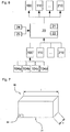
- a freight container 30, as this in Fig. 7 is shown to be introduced into the cargo hold.
- the freight loading system according to the invention is special suitable for transporting bulky containers which have to be rotated for stowage within the cargo hold.
- the cargo loading system may be used in conjunction with significantly smaller cargo containers 30 of any size.
- the in Fig. 7 shown cargo container 30 has a length I, which is significantly longer than the width of in Fig. 1 shown cargo decks 10 so that the freight container 30 during loading in the loading and unloading area using the additional space that offers the door opening 7, must be rotated.
- the cargo deck 10 of in Fig. 1 The aircraft shown in FIG. 2 is configured such that a first freight loading track A and a second freight loading track B are available for receiving individual freight containers 30. For this purpose, along a median plane 5 of the cargo deck 10 middle bars 11, 11 ', 11 ", 11'" are arranged.
- the cargo loading tracks A, B have a width substantially corresponding to the width b of the freight container 30.
- further functional elements are provided in order to hold the freight containers 30 in the cargo loading tracks A, B in a suitable manner.
- the loading and unloading area of the cargo deck 10 of Fig. 1 is equipped with 12 freight conveyors 100, 110, 120, ..., 210.
- freight conveyors 100, 110, 120, ..., 210 are distributed over the loading and unloading area.
- the freight conveyors 100, 110, 120, ..., 210 are distributed over the loading and unloading area such that a freight container 30 to be loaded with a cargo floor outline 33, 33 'always has at least two, preferably at least three, freight conveyors 100, regardless of its position. 110, 120, ..., 210 covered.
- the freight conveyors 100, 110, 120, ..., 210 are arranged in a grid comprising a plurality of rows (in the x-direction) and columns (in the y-direction).
- Each line of in Fig. 1 configuration shown comprises three freight conveyors 100, 110, 120, ..., 210 and each column four freight conveyors 100, 110, 120, ..., 210.
- any other distribution of the cargo handling devices 100, 110, 120, ..., 210 can be selected to achieve a full coverage of the loading and unloading area.
- four, five, six, eight or significantly more freight conveyors can be installed in each column or in each row.
- the freight conveyors 100, 110, 120, ..., 210 in symmetrical and asymmetrical configurations so that the specific requirements of the respective cargo hold are fulfilled.
- the Fig. 1 chosen regular configuration has the advantage that the individual positions of the freight conveyors 100, 110, 120, ..., 210 on can easily detect the cargo deck 10.
- any network of freight conveyors 100, 110, 120,..., 210 for equipping the loading and unloading area and to detect the corresponding positions.
- the RFID tag 34 on the freight container 30 (see. Fig. 7 ).
- a retrieved identification number can be used to determine the freight container width b and the freight container length I - ie the dimensions - of the freight container 30.
- the RFID tag 34 may include specific information regarding these dimensions.
- a laser scanner may be disposed on the door opening 7 or at any other suitable location to determine the dimensions of the incoming cargo container 30.
- the freight conveyors 100, 110, 120,..., 210 are configured to transport the incoming freight container 30 and move it to a predetermined position within the cargo loading lanes A, B.
- Cargo floor outlines 33, 33 ' are shown schematically. It can be seen that the already slightly transverse cargo container 30 has been displaced with respect to the first cargo floor outline 33 along the x-axis by means of the cargo conveyors 100, 110, 120, ..., 210 to take the position illustrated by the second cargo floor outline 33 '.
- the freight conveyors 100, 110, 120,..., 210 used may, for example, be such as those in the DE 198 07 229 A1 are described.
- freight conveyors 100, 110, 120, ..., 210 are used, which have a very low height, so that their installation can be operated with very little effort. Due to the control of the cargo loading system according to the invention, it is possible to operate the shown plurality of freight conveyors 100, 110, 120, ..., 210 in parallel parallel to each other such that the individual freight conveyors 100, 110, 120, ..., 210 are significantly less powerful have to raise. In this respect, the desired construction measures can be implemented without further ado.
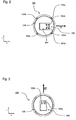
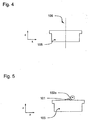
- the Fig. 2 to 5 show examples Detailed views of the cargo conveyor 100.
- the cargo conveyor 100 has an annular frame 105 and a circular rotation plate 103 arranged in the frame 105.
- the rotation plate 103 is rotatably supported within the frame 105 such that it can rotate about an axis of rotation 106 in the xy plane .
- the freight conveyor 100 has corresponding actuators and sensors, so that the rotation plate 103 can be arbitrarily aligned within the frame 105.
- the sensors provide information about the orientation of the rotary actuator 103 within the frame 105.
- the FIGS. 2 and 3 show two different orientations of the rotary actuator 103.
- the rotation plate 103 houses a roller drive unit 101 which drives drive rollers 102a, 102b.
- the drive rollers 102a, 102b are configured to drive cargo 30 in a direction transverse to the axis of rotation of the drive rollers 102a, 102b substantially within the xy plane.
- the Fig. 2 shows the cargo conveyor 100, which is aligned so that it can transport the cargo in a first conveying direction f1. It should be apparent to those skilled in the art that the packages 30 can be driven in an opposite direction of rotation in the opposite direction by driving the drive rollers 102a, 102b. In the Fig. 2 Orientation shown is called a basic position and corresponds to a further zero-degree orientation.
- the rotation plate 103 of the freight conveyor 100 in the Fig. 3 rotated by 90 degrees (angle 270 °), so that now a promotion of freight containers 30 in the second conveying direction f2 is possible.
- the preferred cargo conveyor 100 further includes four sensor devices 104a, 104b, 104c, 104d disposed on the frame 105.
- the orientation of the rotary actuator 103 does not affect the position of the sensor devices 104a, 104b, 104c, 104d.
- the sensor devices 104a, 104b, 104c, 104d are each arranged on the opposite side of the frame 105.
- the first sensor device 104a is located in the 45-degree range of the freight conveyor 100, the second sensor device 104b in the 135-degree range, the third sensor device 104c in the 225-degree range and the fourth sensor device 104d in the 315-degree range.
- the sensor devices 104a, 104b, 104c, 104d are light sensors comprising light emitting diodes and photodiodes such that the sensor devices 104a, 104b, 104c, 104d are adapted to detect the presence of a cargo immediately above the sensor devices 104a, 104b, 104c, 104d detect.
- the cargo conveyor 100 is designed to move the drive rollers 102a, 102b from a rest position into a drive position (FIG. Fig. 5 ) to pivot.
- the drive rollers 102a, 102b are sunk within the rotary actuator 103, so that they do not protrude beyond the frame 105.
- the drive rollers 102a, 102b protrude beyond the frame 105 and can drive cargo.
- the pivoting between the rest position and the drive position is useful to prevent damage to the cargo conveyor 100 by a laterally approaching the drive rollers 102a, 102b freight.
- the sensor devices 104a, 104b, 104c, 104d can be used to determine whether an extension of the drive rollers 102a, 102b from the rest position into the drive position makes sense.
- the cargo loading system comprises the control device 20 communicatively connected to the individual freight conveyors 100, 110, 120, ..., 210 and the associated sensor devices 104a, 104b, 104c, 104d for effective control of the cargo conveyors 100, 110, 120, ..., 210 to accomplish.
- the present invention makes use of the fact that, owing to the multiplicity of available sensor devices 104a, 104b, 104c, 104d, an effective position determination of the freight container 30 can be made.
- the control device 20 receives, via the freight conveyors 100, 110, 120,..., 210, the individual signals of the respective sensor devices 104a, 104b, 104c, 104d. Furthermore, it receives signals from the RFID reader 25, which indicate the dimensions of the cargo floor 31 of the freight container 30.
- the control device 20 knows the positions of the individual sensor devices 104a, 104b, 104c, 104d and can thus assign the signals to specific positions on the cargo deck 10.
- the control device 20 thus results in a cover pattern, which indicates at which point one of the sensor devices 104a, 104b, 104c, 104d of the freight conveyors 100, 110, 120, ..., 210 is covered by the cargo floor 31 of the freight container 30.
- the position of the freight container 30 on the cargo deck 10 can be determined relatively accurately. For example, considering the cargo floor contours 33 indicating a first position of the freight container 30, the first cargo conveyor 100, the second cargo conveyor 110, the third cargo conveyor 120, the sixth cargo conveyor 150, the seventh cargo conveyor 160, the eighth cargo conveyor, are shown to be the eighth cargo conveyor 170 and the twelfth cargo conveyor 210 are completely obscured by the freight container 30.
- the respective sensor devices 104a, 104b, 104c, 104d can output corresponding signals to the control device 20. Since the control device 20 knows the dimensions of the freight container 30, the position of the freight container 30 can be determined relatively accurately within certain tolerances.
- the storage device 21 can store either absolute positions of the sensor devices 104a, 104b, 104c, 104d of the respective freight conveyors 100, 110,..., 210.
- relative position information may be available, for example, allowing the relative position of the cargo conveyor 100 to be determined to the cargo conveyor 110 or 120.
- the relative positions may refer to the sensor devices 104a, 104b, 104c, 104d.
- a relative indication with respect to the sensor device 104a of the freight conveyor 100 can be stored to the sensor device 104a of the freight conveyor 110.
- Numerous other possibilities should be known to the person skilled in the art as to how corresponding position data can be stored on the memory device 21 so that it is possible for the control device 20 to determine the position of the freight container 30 on the cargo deck 10 on the basis of the overlap pattern.
- a virtual image (two-dimensional or three-dimensional) is created by means of a model generator 22 in a virtual model of the sensor devices 104a, 104b, 104c, 104d (in this case, the positions of the individual sensor devices 104a, 104b, 104c, 104d are particularly important ) is shifted so long until a virtual configuration results, which would lead to a signal pattern that corresponds to the currently present signals of the respective sensor devices 104a, 104b, 104c, 104d.
- the model generator 22 not only generates a virtual network of the sensor devices 104a, 104b, 104c, 104d, but also takes into account further physical conditions of the cargo compartment (eg side boundaries, eg in the form of the side walls 1, 2), the position of the door opening 7 , existing functional elements eg in the form of locking elements, etc.).
- the model generator 22 knows that when loading the freight containers 30, only containers of certain standard dimensions (e.g., 88 x 125 inches, 96 x 125 inches, 196 x 96 inches, 238.5 x 96 inches, etc.) are used.
- the control device 20 can take this information into account when determining the position.
- the model generator 22 may generate a complete three-dimensional model of at least the loading and unloading area of the cargo hold.
- the control device 20 stores corresponding position data in a memory device 21 and uses the stored information to determine the movement of the freight container 30 on the cargo deck 10. It should be apparent to those skilled in the art that the control device 20 can receive a plurality of signals to do much more detailed modeling of the movement of the cargo container 30.
- An interrogation of the sensor devices 104a, 104b, 104c, 104d takes place at least at one hertz, preferably at 10 hertz or 100 hertz, so that a very accurate position determination and / or modeling of the motion sequences let create.
- the control device 20 now uses this information to set the freight conveyors 100, 110, 120,..., 210 in a suitable manner.
- the controller 20 may determine that the cargo container is moving above the second cargo conveyor at a certain speed in a particular direction.
- this relative movement r is indicated with a corresponding vector arrow.
- the control device 20 can now align the second freight conveyor 210 (eg, to a zero-degree angle) such that the axis of rotation of the drive rollers 102a, 102b is substantially perpendicular to this determined relative movement r, so that an effective drive of the freight container 30 with minimal Wear is possible.
- cargo conveyors 100, 110, 120, ..., 210 which are not yet covered by the freight container 30, can already be controlled in such a way that they are already properly aligned as soon as they are covered.
- the information obtained with respect to the movement of the freight container 30 can be used to transport it semiautomatically or fully automatically to a desired position, for example into the freight loading track B.
- a user of the freight loading system according to the invention for example via an input device 24, enter a desired position for the freight container 30.
- the control device 20 thus knows an actual position and a target position and can develop a corresponding conveying strategy in order to convey the freight container 30 from the actual position to the target position.
- the control device 20 may come to the conclusion that the freight container 30 must be rotated from the second position according to the second cargo floor outline 33 'in a clockwise direction in order to park it in the freight loading lane B.
- the control device 20 can therefore determine a desired conveying direction s for each freight conveyor 100, 110, 120,..., 210, which is covered by the freight container 30, and determine this desired conveying direction in the control of the freight conveyor 100, 110, 120, ..., 210 take into account.
- Fig. 1 is the target conveying direction s symbolized by a corresponding vector arrow. It would thus be possible to stop the freight container 30, to properly align the second cargo conveyor and all other affected freight conveyors and then to transport the freight container 30 in a corresponding direction.
- the control device 20 determines at a given time the relative movement r for a specific cargo conveyor, for example for the second cargo conveyor 110, and a corresponding desired conveying direction s. On the basis of these values, a setting of the freight conveyors 100, 110, 120,..., 210 is determined, which initiates a suitable course correction. In this respect, the freight container 30 is continuously pivoted into the freight loading track B, with only very little wear on the freight conveyors 100, 110, 120,..., 210 occurring.
- the described configuration of the cargo deck 10 with the sensor devices 104a, 104b, 104c, 104d of the respective cargo conveyors 100, 110, 120, ..., 210 is used to create a virtual image of the cargo floor 31 of the freight container and to compare this virtual image with stored two-dimensional or three-dimensional models of the cargo hold, in order then to mathematically control the freight conveyors 100, 110, 120,..., 210, in particular the respective rotary actuators 103 (direction of rotation of the drive rollers 102a, 102b, orientation of the Rotation plate 103) that it is possible to rotate the freight container 30 semi-automatically or fully automatically into the cargo hold.
- This can avoid unnecessary wear.
- the freight loading system according to the invention may have two or three-dimensional models of all common freight container models stored in the storage device 21.
- the user of the cargo loading system according to the invention it is possible to select the appropriate freight container 30.
- an automatic detection of the freight container model can take place.
- the cargo loading system according to the invention it is even possible to load cargo container 30 with overhang.
- corresponding data that is suitable for creating a two- or three-dimensional model of the freight container with overhang can be stored on the aforementioned RFID tag 34.
- the control device 20 can determine an optimal control plan on the basis of the models of the cargo hold and the freight container 30, so that there is no collision of the freight container 30 with the aircraft, in particular its outer skin.
- the freight container 30 can be completely aligned with functional elements which are arranged along the right-hand side wall 2 opposite the door opening 7.
- the sensor devices 104a, 104b, 104c, 104d are arranged on the freight conveyors 100, 110, 120,..., 210, it would also be possible to separate a part or all of them separately from the freight conveyors 100, 110. 120, ..., 210 provide.
- a network or grid of sensor devices 104a, 104b, 104c, 104d that is completely independent of the freight conveyors 100, 110, 120,..., 210 could be configured.
Landscapes
- Engineering & Computer Science (AREA)
- Aviation & Aerospace Engineering (AREA)
- Control Of Conveyors (AREA)
- Warehouses Or Storage Devices (AREA)
Claims (19)
- Système de chargement de fret pour le chargement et le déchargement d'un pont de fret (10), incluant :- une pluralité de systèmes de convoyage de fret (100, 110, ..., 210) comportant chacun au moins un rouleau (102a, 102b) pour le convoyage de pièces de fret (30) dans une direction de convoyage (f1, f2) et comportant chacun au moins un capteur (104a, 104b, 104c, 104d) pour détecter la présence d'une pièce de fret, dans lequel les rouleaux (102a, 102b) d'au moins un système de convoyage de fret (110, 120, ..., 200) sont montés mobiles en rotation de telle façon que la direction de convoyage (f1, f2) du premier système de convoyage de fret (110, 120, ..., 210) est réglable,- une commande (20) qui reçoit des signaux provenant des capteurs (104a, 104b, 104c, 104d) d'au moins deux systèmes de convoyage de fret (100, 110, ..., 210), afin d'appréhender un mouvement d'une pièce de fret (30),caractérisé en ce que
la commande (20) est réalisée pour, au moyen des signaux, calculer un mouvement relatif (r) d'une portion de la pièce de fret (30) par rapport au premier système de convoyage de fret (100, 110, ..., 200) et pour orienter ledit au moins un rouleau (102a, 102b) du premier système de convoyage de fret (100, 110, ..., 200) en prenant en compte le mouvement relatif (r) de la portion de la pièce de fret (30),
dans lequel au moins un groupe partiel des capteurs (104a, 104b, 104c, 104d) et/ou une pluralité de systèmes de convoyage de fret (100, 110, ..., 200) sont agencés selon une trame qui couvre le pont de fret (10) dans sa largeur, dans la zone de chargement et de déchargement du pont de fret (10). - Système de chargement de fret selon la revendication 1,
caractérisé en ce que la commande (20) est réalisée pour orienter le premier système de convoyage de fret pendant que le rouleau (102a, 102b) est appliqué en coopération de forces contre une portion de la pièce de fret (30), afin d'entraîner la pièce de fret (30). - Système de chargement de fret selon l'une des revendications précédentes,
caractérisé en ce que la commande (20) inclut un moyen formant mémoire (21) qui mémorise des données concernant les positions des capteurs (104a, 104b, 104c, 104d) les uns par rapport aux autres et/ou sur le pont de fret (10), ladite commande (20) étant réalisée pour calculer le mouvement relatif (r) de la portion de la pièce de fret (30) en utilisant les données du moyen formant mémoire (21). - Système de chargement de fret selon l'une des revendications précédentes,
caractérisé en ce que la commande (20) est réalisée pour détecter une dimension d'une surface au sol de la pièce de fret (30) et pour la traiter pour une détermination d'une position de la pièce de fret (30) et/ou du mouvement relatif (r) de la portion de la pièce de fret (30). - Système de chargement de fret selon l'une des revendications précédentes,
caractérisé en ce que les capteurs (104a, 104b, 104c, 104d) incluent des capteurs de lumière, qui sont agencés sur le pont de fret (10) de telle façon et qui sont réalisés de telle manière qu'ils détectent au moins la présence d'une pièce de fret (30) indirectement via les capteurs de lumière. - Système de chargement de fret selon l'une des revendications précédentes,
caractérisé en ce qu'au moins un groupe partiel des systèmes de convoyage de fret (100, 110, ..., 200) incluent chacun au moins quatre capteurs, qui sont agencés de manière statique par rapport au pont de fret (10), à savoir sur un cadre des systèmes de convoyage de fret (100, 110, ..., 210). - Système de chargement de fret selon la revendication 6,
caractérisé en ce que les capteurs (104a, 104b, 104c, 104d) sont agencés au niveau du système de convoyage de fret (100, 110, ..., 200) respectif de façon à entourer ledit au moins un rouleau (102a, 102b). - Système de chargement de fret selon l'une des revendications précédentes,
caractérisé en ce que les signaux indiquent un motif de recouvrement binaire. - Système de chargement de fret selon l'une des revendications précédentes,
caractérisé en ce que le premier système de convoyage de fret (100, 110, ..., 200) inclut au moins un plateau rotatif (103), qui est agencé dans un cadre (105) avec faculté de rotation autour d'un axe vertical (106) et qui abrite ledit au moins un rouleau (102a, 102b), afin de régler le rouleau (102a, 102b) pour le convoyage de la pièce de fret (30) dans une direction de convoyage prédéterminée (f1, f2). - Système de chargement de fret selon l'une des revendications précédentes,
caractérisé par un moyen de lecture pour détecter le type de la pièce de fret et/ou au moins une dimension de la pièce de fret (30). - Système de chargement de fret selon l'une des revendications précédentes,
caractérisé en ce que la commande (20) inclut un générateur de modèle (22), pour établir un modèle au moins bidimensionnel de la pièce de fret (30) et/ou d'au moins une partie de la soute à fret de l'avion. - Système de chargement de fret selon l'une des revendications précédentes,
caractérisé en ce que la commande (20) inclut un moyen de mémorisation de position, afin de mémoriser des données de position dans une succession temporelle, qui indiquent des positions de la pièce de fret (30) sur le pont de fret (10), ladite commande (20) étant réalisée pour déterminer, au moyen d'une position réelle déterminée et des données de position mémorisées provenant du moyen de mémorisation de position, le mouvement de la pièce de fret (30). - Système de chargement de fret selon l'une des revendications précédentes,
caractérisé en ce que la commande (20) est réalisée pour déterminer une position de consigne et une position réelle de la pièce de fret (30) et pour piloter au moins un système de convoyage de fret (110, 120, ..., 200) de telle manière que la pièce de fret (30) est convoyée depuis la position réelle jusque dans la position de consigne. - Système de chargement de fret selon la revendication 13,
caractérisé en ce que la commande (20) est réalisée pour déterminer, au moyen de la position réelle et de la position de consigne, une direction de convoyage de consigne (s) pour au moins un système de convoyage de fret (100, 110, ..., 210). - Système de chargement de fret selon la revendication 14,
caractérisé en ce que la commande (20) est réalisée pour déterminer, en tenant compte du mouvement relatif (r), une direction de convoyage optimale pour au moins un système de convoyage de fret (100, 110, ..., 200), et lorsqu'il adopte la direction de convoyage optimale, l'axe du rouleau du système de convoyage de fret (100, 110, ..., 200) respectif s'étend sensiblement perpendiculairement au mouvement relatif (r) de la pièce de fret reposant sur le rouleau. - Système de chargement de fret selon la revendication 15,
caractérisé en ce que la commande (20) est réalisée pour calculer, à partir de la direction de convoyage optimale et de la direction de convoyage de consigne (s), une direction de convoyage de positionnement, et pour orienter ledit au moins un système de convoyage de fret (100, 110, ..., 200) d'après la direction de convoyage optimale. - Système de chargement de fret selon la revendication 13 ou 14, caractérisé en ce que la commande (20) est réalisée pour :- déterminer en temps réel le mouvement relatif (r) de la pièce de fret (30) au voisinage de ou à la position, à laquelle ledit au moins un rouleau (102a, 102b) dudit au moins un système de convoyage de fret (100, 110, ..., 200) du système de convoyage de fret (100, 110, ..., 200) vient en engagement, et pour déterminer une direction de convoyage de consigne (s), et- orienter le rouleau (102a, 102b) en tenant compte du mouvement relatif (r) de la pièce de fret (30) et de la direction de convoyage de consigne (s).
- Procédé pour déterminer un mouvement d'une pièce de fret sur un pont de fret (10) et pour orienter au moins un système de convoyage de fret (100, 110, ..., 200), dans lequel au moins un groupe partiel de capteurs (104a, 104b, 104c, 104d) et/ou une pluralité de systèmes de convoyage de fret (100, 110, ..., 210) sont agencés sur le pont de fret (10) suivant une trame qui coiffe le pont de tête (10) dans sa largeur, dans la zone de chargement et de déchargement du pont de fret (10), le procédé incluant les étapes consistant à :- déterminer les dimensions et/ou la configuration d'une surface au sol (31) de la pièce de fret (30) au moyen d'une commande (20) ;- recevoir une pluralité de premiers signaux provenant des capteurs (104a, 104b, 104c, 104d), qui sont agencés de façon répartie au moins sur une portion du pont de fret (10), lesdits premiers signaux indiquant une couverture par la pièce de fret (30) à un premier instant ;- calculer une première position de la pièce de fret (30) au moyen des premiers signaux en tenant compte de la dimension et/ou de la configuration de la surface au sol au moins, au moyen de la commande (20) ;- mémoriser la première position de la pièce de fret (30) dans une mémoire (21) ;- recevoir une pluralité de seconds signaux provenant des capteurs (104a, 104b, 104c, 104d) à un second instant ;- calculer une seconde position de la pièce de fret (30) au moyen des seconds signaux en tenant compte de la dimension et/ou de la configuration de la surface au sol (30), au moyen de la commande (20) ;calculer le mouvement de la pièce de fret (30) en comparant la première position de la pièce de fret (30) à la seconde position, et au moyen des signaux on calcule un mouvement relatif (r) d'une portion de la pièce de fret (30) par rapport audit au moins un système de convoyage de fret (100, 110, ..., 200), et on oriente au moins un rouleau (102a, 102b) dudit au moins un système de convoyage de fret (100, 110, ..., 200) en tenant compte du mouvement relatif (r) de la portion de la pièce de fret (30).
- Procédé selon la revendication 18,
caractérisé par
une opération de lecture d'une mémoire appliquée sur la pièce de fret (30), à savoir d'une puce RFID (34), au moyen d'un système de lecture (25) pour la détermination de la dimension et/ou de la configuration au moins de la surface au sol de la pièce de fret.
Applications Claiming Priority (2)
| Application Number | Priority Date | Filing Date | Title |
|---|---|---|---|
| DE102010060145 | 2010-10-25 | ||
| DE102011000743.1A DE102011000743B4 (de) | 2010-10-25 | 2011-02-15 | Frachtladesystem und Verfahren zum Ermitteln einer Bewegung eines Frachtstücks auf einem Frachtdeck |
Publications (3)
| Publication Number | Publication Date |
|---|---|
| EP2444320A2 EP2444320A2 (fr) | 2012-04-25 |
| EP2444320A3 EP2444320A3 (fr) | 2013-09-11 |
| EP2444320B1 true EP2444320B1 (fr) | 2018-06-27 |
Family
ID=44970952
Family Applications (1)
| Application Number | Title | Priority Date | Filing Date |
|---|---|---|---|
| EP11185941.9A Active EP2444320B1 (fr) | 2010-10-25 | 2011-10-20 | Système de charge de cargaison et procédé de détermination du mouvement d'une pièce de cargaison sur un toit de cargaison |
Country Status (3)
| Country | Link |
|---|---|
| US (1) | US9650139B2 (fr) |
| EP (1) | EP2444320B1 (fr) |
| DE (1) | DE102011000743B4 (fr) |
Families Citing this family (23)
| Publication number | Priority date | Publication date | Assignee | Title |
|---|---|---|---|---|
| DE102011002276B4 (de) * | 2011-04-27 | 2016-05-04 | Telair International Gmbh | Frachtdeck für einen Frachtraum eines Flugzeugs sowie Verfahren zum Überwachen der Temperatur eines auf einem Frachtraumboden angeordneten Containers, einer Palette oder eines Unit Load Device (ULD) |
| DE102011051007A1 (de) | 2011-06-10 | 2012-12-13 | Telair International Gmbh | Frachtdeck, Frachtladesystem und Verfahren zum Be-/Entladen eines Frachtraums |
| DE102014105657A1 (de) * | 2014-04-22 | 2015-10-22 | Telair International Gmbh | Frachtladesystem für das Be- und Entladen eines Frachtstücks, Verfahren zur Erstellung und/oder Aktualisierung eines Ladeplans |
| US9266463B2 (en) | 2014-06-04 | 2016-02-23 | Federal Express Corporation | Device, system, and method for limiting movement of a cargo container in a cargo area |
| KR101646369B1 (ko) * | 2014-10-31 | 2016-08-12 | 현대자동차주식회사 | 하이브리드 차량의 타력주행 유도 제어장치 및 방법 |
| US9446846B1 (en) * | 2015-03-31 | 2016-09-20 | Goodrich Corporation | Multi directional input cargo moving system |
| KR20160134977A (ko) * | 2015-05-14 | 2016-11-24 | 한국전자통신연구원 | 화물 적재 시스템 및 화물 적재 방법 |
| US20180203471A1 (en) * | 2015-07-16 | 2018-07-19 | Sikorsky Aircraft Corporation | Clearance sensor system |
| EP3312084B1 (fr) | 2016-10-20 | 2019-06-26 | Airbus Operations GmbH | Unite d'entrainement de cargaison avec detection de mouvement |
| US10246190B2 (en) * | 2016-12-16 | 2019-04-02 | Goodrich Corporation | Adaptive optical sensor for container presence and motion |
| US10018720B1 (en) | 2016-12-16 | 2018-07-10 | Goodrich Corporation | Adaptive optical sensor for container presence and motion |
| US10005564B1 (en) | 2017-05-05 | 2018-06-26 | Goodrich Corporation | Autonomous cargo handling system and method |
| US11203431B2 (en) * | 2018-10-22 | 2021-12-21 | Goodrich Corporation | Self-calibrating multi-sensor cargo handling system and method |
| CN109606232B (zh) * | 2019-01-29 | 2024-06-18 | 浙江飞碟汽车制造有限公司 | 载货汽车用柔性平台装置 |
| US11535453B2 (en) * | 2020-02-20 | 2022-12-27 | Goodrich Corporation | Automatic electromechanical braking roller systems and methods |
| US11958628B2 (en) | 2020-04-14 | 2024-04-16 | Goodrich Corporation | Systems and methods for run-time self-assessment of cargo handling systems |
| US12084201B2 (en) * | 2020-04-14 | 2024-09-10 | Goodrich Corporation | Distributed control of autonomous cargo handling systems |
| US12060165B2 (en) * | 2020-04-14 | 2024-08-13 | Goodrich Corporation | Systems and methods for safely operating autonomous cargo handling systems |
| US12085914B2 (en) | 2020-04-14 | 2024-09-10 | Goodrich Corporation | Systems and methods for operating multiple-level autonomous cargo handling systems |
| DE102021118250A1 (de) | 2021-07-14 | 2023-01-19 | Airbus Ds Airborne Solutions Gmbh | Frachtladesystem und Frachtladeverfahren zum Laden von ULDs in ein Luftfahrzeug |
| EP4140923B1 (fr) | 2021-08-27 | 2025-08-20 | Airbus Operations GmbH | Système de chargement de fret à commande dynamique pour un aéronef |
| KR20230107983A (ko) * | 2022-01-10 | 2023-07-18 | 현대자동차주식회사 | 화물 로딩 및 언로딩 장치 |
| US12576968B2 (en) * | 2024-02-16 | 2026-03-17 | Goodrich Corporation | Pallet skew correction |
Family Cites Families (22)
| Publication number | Priority date | Publication date | Assignee | Title |
|---|---|---|---|---|
| US4050655A (en) | 1976-06-01 | 1977-09-27 | The Boeing Company | Cargo loading method and apparatus |
| US5868544A (en) * | 1996-10-11 | 1999-02-09 | Mcdonnell Douglas Corporation | Airborne cargo loader |
| DE19807231A1 (de) * | 1998-02-20 | 1999-09-02 | Telair Int Gmbh | Frachtladesystem |
| DE19807229C2 (de) | 1998-02-20 | 1999-12-23 | Telair Int Gmbh | Rollenantriebseinheit und Ladesystem mit Sensoren und einer Steuerlogik, insbesondere zum motorgetriebenen Anheben und Absenken der Antriebsrollen von Rollenantriebseinheiten |
| US6420846B1 (en) * | 1999-10-19 | 2002-07-16 | Lucas Western Inc. | Power drive unit with stall sensor |
| DE10054821A1 (de) * | 2000-11-04 | 2002-05-23 | Wittenstein Gmbh & Co Kg | Verfahren und Vorrichtung zum Beladen eines Flugzeuges |
| DE10158298C1 (de) | 2001-11-23 | 2003-04-10 | Esw Extel Systems Wedel Ges Fu | Einrichtung und Verfahren zum Drehen von Frachtpaletten in Luftfahrzeugen |
| DE10212123B4 (de) * | 2002-03-19 | 2008-10-30 | Telair International Gmbh | Frachtladesystem in einem Laderaum eines Flugzeugs |
| GB0215580D0 (en) | 2002-07-05 | 2002-08-14 | Lucas Western Inc | Cargo loading system |
| EP1620312B1 (fr) * | 2003-05-02 | 2007-09-19 | Ancra International, Llc | Bloc d'entrainement de charge orientable /escamotable |
| DE10338704A1 (de) * | 2003-08-22 | 2005-03-24 | Telair International Gmbh | Frachtladesystem |
| US7324921B2 (en) * | 2004-12-28 | 2008-01-29 | Rftrax Inc. | Container inspection system |
| DE102005008443B4 (de) | 2005-02-24 | 2009-06-18 | Airbus Deutschland Gmbh | Ladevorrichtung zum zumindest teilautomatischen Beladen und Entladen eines Frachtraums eines Verkehrsmittels |
| DE102005021078B4 (de) | 2005-05-06 | 2010-07-15 | Rheinmetall Defence Electronics Gmbh | Frachtladesystem |
| US7199543B1 (en) * | 2005-12-13 | 2007-04-03 | Goodrich Corporation | Power drive unit with unit load device sensor |
| US20100213313A1 (en) * | 2006-11-06 | 2010-08-26 | Goodrich Corporation | Integrated aircraft cargo loading and cargo video monitoring system |
| US8515656B2 (en) * | 2007-11-02 | 2013-08-20 | Goodrich Corporation | Integrated aircraft cargo loading and monitoring system |
| US20090121085A1 (en) | 2007-11-13 | 2009-05-14 | Goodrich Corporation | Infrared Communication System for Activating Power Drive Units in an Aircraft Cargo Loading System |
| US8220750B2 (en) * | 2007-11-13 | 2012-07-17 | Goodrich Corporation | Infrared communication power drive unit and method for activating same in an aircraft cargo loading system |
| FR2935184B1 (fr) * | 2008-08-20 | 2018-03-09 | Goodrich Corporation | systeme integre de chargement et de controle du fret d'un avion |
| US7988391B2 (en) | 2009-02-17 | 2011-08-02 | Goodrich Corporation | Self-locking, overrideable and attenuating cargo guide and restraint |
| DE102009020039A1 (de) * | 2009-05-05 | 2010-11-25 | Rheinmetall Defence Electronics Gmbh | Verfahren zur Bestimmung der Position eines Frachtstücks |
-
2011
- 2011-02-15 DE DE102011000743.1A patent/DE102011000743B4/de active Active
- 2011-10-20 EP EP11185941.9A patent/EP2444320B1/fr active Active
- 2011-10-25 US US13/280,926 patent/US9650139B2/en not_active Expired - Fee Related
Non-Patent Citations (1)
| Title |
|---|
| None * |
Also Published As
| Publication number | Publication date |
|---|---|
| DE102011000743A1 (de) | 2012-04-26 |
| US20120101636A1 (en) | 2012-04-26 |
| EP2444320A3 (fr) | 2013-09-11 |
| DE102011000743B4 (de) | 2021-03-18 |
| US9650139B2 (en) | 2017-05-16 |
| EP2444320A2 (fr) | 2012-04-25 |
Similar Documents
| Publication | Publication Date | Title |
|---|---|---|
| EP2444320B1 (fr) | Système de charge de cargaison et procédé de détermination du mouvement d'une pièce de cargaison sur un toit de cargaison | |
| EP2937279B1 (fr) | Système de charge de fret pour le chargement/déchargement de fret, procédé de création et/ou de mise à jour d'un plan de chargement | |
| EP2665646B1 (fr) | Système de chargement d'un avion et procédé de transport d'une marchandise de fret sur une plate-forme de chargement | |
| EP2675709B1 (fr) | Système de chargement du cargo et méthode de commande d'un convoyeur multiple | |
| EP3601118B1 (fr) | Système de production équipé d'un ftf servant à automatiser la distribution de contenants sur des rayonnages de prélèvement | |
| EP2151402B1 (fr) | Système logistique | |
| EP2532582B1 (fr) | Soute, système de chargement de cargaison et procédé de chargement/déchargement d'une soute | |
| EP0656868B1 (fr) | Procede et dispositif de commande d'un pont dechargeur pour conteneurs | |
| EP3894349B1 (fr) | Système de chargement de conteneurs et procédé de surveillance du fonctionnement dans ce dernier | |
| EP3529193B1 (fr) | Procédé pour le positionnement automatique d'un chariot-portail-élévateur pour conteneurs et chariot-portail-élévateur correspondant | |
| DE102019001125B4 (de) | Fördereinrichtung für Ladungsträger mit integrierter Kollisionsdetektion | |
| EP2602216B1 (fr) | Système logistique, station de transmission pour celui-ci et procédé logistique | |
| EP4457160A1 (fr) | Système de stockage modulaire, procédé de construction d'un système de stockage et procédé de stockage | |
| EP2539205B1 (fr) | Système de transport avec tracteurs | |
| DE202019102253U1 (de) | Vorrichtung zum Verifizieren von Lagergut-Positionen in intralogistischen Lagersystemen | |
| DE102011000819A1 (de) | Ladesystem für ein Flugzeug und Verfahren zur Förderung eines Frachtstücks auf einem Frachtdeck | |
| EP2657155B1 (fr) | Protection électronique contre la chute pour navette autonome avec mesure de trajectoire et orientation | |
| EP3924576B1 (fr) | Système de stationnement automatique pour véhicules | |
| EP4269321B1 (fr) | Dispositif de transport pour porteurs de charge | |
| EP2386506B1 (fr) | Système logistique avec un entraînement de plaques qui glissent latéralement | |
| WO2024175791A1 (fr) | Dispositif de transport vertical pour un système de stockage modulaire, procédé de transport vertical dans un système de stockage modulaire et système de stockage modulaire avec un dispositif de transport vertical | |
| EP3984858B1 (fr) | Procédé de détermination des informations sur la propagation d'un support de marchandises dans un chariot de manutention à fonctionnement au moins partiellement automatisé |
Legal Events
| Date | Code | Title | Description |
|---|---|---|---|
| AK | Designated contracting states |
Kind code of ref document: A2 Designated state(s): AL AT BE BG CH CY CZ DE DK EE ES FI FR GB GR HR HU IE IS IT LI LT LU LV MC MK MT NL NO PL PT RO RS SE SI SK SM TR |
|
| AX | Request for extension of the european patent |
Extension state: BA ME |
|
| PUAI | Public reference made under article 153(3) epc to a published international application that has entered the european phase |
Free format text: ORIGINAL CODE: 0009012 |
|
| PUAL | Search report despatched |
Free format text: ORIGINAL CODE: 0009013 |
|
| AK | Designated contracting states |
Kind code of ref document: A3 Designated state(s): AL AT BE BG CH CY CZ DE DK EE ES FI FR GB GR HR HU IE IS IT LI LT LU LV MC MK MT NL NO PL PT RO RS SE SI SK SM TR |
|
| AX | Request for extension of the european patent |
Extension state: BA ME |
|
| RIC1 | Information provided on ipc code assigned before grant |
Ipc: B64D 9/00 20060101AFI20130808BHEP |
|
| 17P | Request for examination filed |
Effective date: 20140310 |
|
| RBV | Designated contracting states (corrected) |
Designated state(s): AL AT BE BG CH CY CZ DE DK EE ES FI FR GB GR HR HU IE IS IT LI LT LU LV MC MK MT NL NO PL PT RO RS SE SI SK SM TR |
|
| 17Q | First examination report despatched |
Effective date: 20170406 |
|
| GRAP | Despatch of communication of intention to grant a patent |
Free format text: ORIGINAL CODE: EPIDOSNIGR1 |
|
| INTG | Intention to grant announced |
Effective date: 20180116 |
|
| GRAS | Grant fee paid |
Free format text: ORIGINAL CODE: EPIDOSNIGR3 |
|
| GRAA | (expected) grant |
Free format text: ORIGINAL CODE: 0009210 |
|
| AK | Designated contracting states |
Kind code of ref document: B1 Designated state(s): AL AT BE BG CH CY CZ DE DK EE ES FI FR GB GR HR HU IE IS IT LI LT LU LV MC MK MT NL NO PL PT RO RS SE SI SK SM TR |
|
| REG | Reference to a national code |
Ref country code: GB Ref legal event code: FG4D Free format text: NOT ENGLISH |
|
| REG | Reference to a national code |
Ref country code: AT Ref legal event code: REF Ref document number: 1012069 Country of ref document: AT Kind code of ref document: T Effective date: 20180715 |
|
| REG | Reference to a national code |
Ref country code: IE Ref legal event code: FG4D Free format text: LANGUAGE OF EP DOCUMENT: GERMAN |
|
| REG | Reference to a national code |
Ref country code: DE Ref legal event code: R096 Ref document number: 502011014371 Country of ref document: DE |
|
| REG | Reference to a national code |
Ref country code: FR Ref legal event code: PLFP Year of fee payment: 8 |
|
| PG25 | Lapsed in a contracting state [announced via postgrant information from national office to epo] |
Ref country code: LT Free format text: LAPSE BECAUSE OF FAILURE TO SUBMIT A TRANSLATION OF THE DESCRIPTION OR TO PAY THE FEE WITHIN THE PRESCRIBED TIME-LIMIT Effective date: 20180627 Ref country code: BG Free format text: LAPSE BECAUSE OF FAILURE TO SUBMIT A TRANSLATION OF THE DESCRIPTION OR TO PAY THE FEE WITHIN THE PRESCRIBED TIME-LIMIT Effective date: 20180927 Ref country code: FI Free format text: LAPSE BECAUSE OF FAILURE TO SUBMIT A TRANSLATION OF THE DESCRIPTION OR TO PAY THE FEE WITHIN THE PRESCRIBED TIME-LIMIT Effective date: 20180627 Ref country code: NO Free format text: LAPSE BECAUSE OF FAILURE TO SUBMIT A TRANSLATION OF THE DESCRIPTION OR TO PAY THE FEE WITHIN THE PRESCRIBED TIME-LIMIT Effective date: 20180927 Ref country code: SE Free format text: LAPSE BECAUSE OF FAILURE TO SUBMIT A TRANSLATION OF THE DESCRIPTION OR TO PAY THE FEE WITHIN THE PRESCRIBED TIME-LIMIT Effective date: 20180627 |
|
| REG | Reference to a national code |
Ref country code: NL Ref legal event code: MP Effective date: 20180627 |
|
| REG | Reference to a national code |
Ref country code: LT Ref legal event code: MG4D |
|
| PG25 | Lapsed in a contracting state [announced via postgrant information from national office to epo] |
Ref country code: HR Free format text: LAPSE BECAUSE OF FAILURE TO SUBMIT A TRANSLATION OF THE DESCRIPTION OR TO PAY THE FEE WITHIN THE PRESCRIBED TIME-LIMIT Effective date: 20180627 Ref country code: GR Free format text: LAPSE BECAUSE OF FAILURE TO SUBMIT A TRANSLATION OF THE DESCRIPTION OR TO PAY THE FEE WITHIN THE PRESCRIBED TIME-LIMIT Effective date: 20180928 Ref country code: LV Free format text: LAPSE BECAUSE OF FAILURE TO SUBMIT A TRANSLATION OF THE DESCRIPTION OR TO PAY THE FEE WITHIN THE PRESCRIBED TIME-LIMIT Effective date: 20180627 Ref country code: RS Free format text: LAPSE BECAUSE OF FAILURE TO SUBMIT A TRANSLATION OF THE DESCRIPTION OR TO PAY THE FEE WITHIN THE PRESCRIBED TIME-LIMIT Effective date: 20180627 |
|
| PG25 | Lapsed in a contracting state [announced via postgrant information from national office to epo] |
Ref country code: NL Free format text: LAPSE BECAUSE OF FAILURE TO SUBMIT A TRANSLATION OF THE DESCRIPTION OR TO PAY THE FEE WITHIN THE PRESCRIBED TIME-LIMIT Effective date: 20180627 |
|
| PG25 | Lapsed in a contracting state [announced via postgrant information from national office to epo] |
Ref country code: RO Free format text: LAPSE BECAUSE OF FAILURE TO SUBMIT A TRANSLATION OF THE DESCRIPTION OR TO PAY THE FEE WITHIN THE PRESCRIBED TIME-LIMIT Effective date: 20180627 Ref country code: SK Free format text: LAPSE BECAUSE OF FAILURE TO SUBMIT A TRANSLATION OF THE DESCRIPTION OR TO PAY THE FEE WITHIN THE PRESCRIBED TIME-LIMIT Effective date: 20180627 Ref country code: CZ Free format text: LAPSE BECAUSE OF FAILURE TO SUBMIT A TRANSLATION OF THE DESCRIPTION OR TO PAY THE FEE WITHIN THE PRESCRIBED TIME-LIMIT Effective date: 20180627 Ref country code: PL Free format text: LAPSE BECAUSE OF FAILURE TO SUBMIT A TRANSLATION OF THE DESCRIPTION OR TO PAY THE FEE WITHIN THE PRESCRIBED TIME-LIMIT Effective date: 20180627 Ref country code: EE Free format text: LAPSE BECAUSE OF FAILURE TO SUBMIT A TRANSLATION OF THE DESCRIPTION OR TO PAY THE FEE WITHIN THE PRESCRIBED TIME-LIMIT Effective date: 20180627 Ref country code: IS Free format text: LAPSE BECAUSE OF FAILURE TO SUBMIT A TRANSLATION OF THE DESCRIPTION OR TO PAY THE FEE WITHIN THE PRESCRIBED TIME-LIMIT Effective date: 20181027 |
|
| PG25 | Lapsed in a contracting state [announced via postgrant information from national office to epo] |
Ref country code: IT Free format text: LAPSE BECAUSE OF FAILURE TO SUBMIT A TRANSLATION OF THE DESCRIPTION OR TO PAY THE FEE WITHIN THE PRESCRIBED TIME-LIMIT Effective date: 20180627 Ref country code: ES Free format text: LAPSE BECAUSE OF FAILURE TO SUBMIT A TRANSLATION OF THE DESCRIPTION OR TO PAY THE FEE WITHIN THE PRESCRIBED TIME-LIMIT Effective date: 20180627 Ref country code: SM Free format text: LAPSE BECAUSE OF FAILURE TO SUBMIT A TRANSLATION OF THE DESCRIPTION OR TO PAY THE FEE WITHIN THE PRESCRIBED TIME-LIMIT Effective date: 20180627 |
|
| REG | Reference to a national code |
Ref country code: DE Ref legal event code: R097 Ref document number: 502011014371 Country of ref document: DE |
|
| PLBE | No opposition filed within time limit |
Free format text: ORIGINAL CODE: 0009261 |
|
| STAA | Information on the status of an ep patent application or granted ep patent |
Free format text: STATUS: NO OPPOSITION FILED WITHIN TIME LIMIT |
|
| PG25 | Lapsed in a contracting state [announced via postgrant information from national office to epo] |
Ref country code: DK Free format text: LAPSE BECAUSE OF FAILURE TO SUBMIT A TRANSLATION OF THE DESCRIPTION OR TO PAY THE FEE WITHIN THE PRESCRIBED TIME-LIMIT Effective date: 20180627 |
|
| REG | Reference to a national code |
Ref country code: CH Ref legal event code: PL |
|
| 26N | No opposition filed |
Effective date: 20190328 |
|
| REG | Reference to a national code |
Ref country code: BE Ref legal event code: MM Effective date: 20181031 |
|
| PG25 | Lapsed in a contracting state [announced via postgrant information from national office to epo] |
Ref country code: LU Free format text: LAPSE BECAUSE OF NON-PAYMENT OF DUE FEES Effective date: 20181020 Ref country code: MC Free format text: LAPSE BECAUSE OF FAILURE TO SUBMIT A TRANSLATION OF THE DESCRIPTION OR TO PAY THE FEE WITHIN THE PRESCRIBED TIME-LIMIT Effective date: 20180627 |
|
| REG | Reference to a national code |
Ref country code: IE Ref legal event code: MM4A |
|
| PG25 | Lapsed in a contracting state [announced via postgrant information from national office to epo] |
Ref country code: BE Free format text: LAPSE BECAUSE OF NON-PAYMENT OF DUE FEES Effective date: 20181031 Ref country code: SI Free format text: LAPSE BECAUSE OF FAILURE TO SUBMIT A TRANSLATION OF THE DESCRIPTION OR TO PAY THE FEE WITHIN THE PRESCRIBED TIME-LIMIT Effective date: 20180627 Ref country code: CH Free format text: LAPSE BECAUSE OF NON-PAYMENT OF DUE FEES Effective date: 20181031 Ref country code: LI Free format text: LAPSE BECAUSE OF NON-PAYMENT OF DUE FEES Effective date: 20181031 |
|
| PG25 | Lapsed in a contracting state [announced via postgrant information from national office to epo] |
Ref country code: IE Free format text: LAPSE BECAUSE OF NON-PAYMENT OF DUE FEES Effective date: 20181020 |
|
| PG25 | Lapsed in a contracting state [announced via postgrant information from national office to epo] |
Ref country code: AL Free format text: LAPSE BECAUSE OF FAILURE TO SUBMIT A TRANSLATION OF THE DESCRIPTION OR TO PAY THE FEE WITHIN THE PRESCRIBED TIME-LIMIT Effective date: 20180627 |
|
| REG | Reference to a national code |
Ref country code: AT Ref legal event code: MM01 Ref document number: 1012069 Country of ref document: AT Kind code of ref document: T Effective date: 20181020 |
|
| PG25 | Lapsed in a contracting state [announced via postgrant information from national office to epo] |
Ref country code: MT Free format text: LAPSE BECAUSE OF FAILURE TO SUBMIT A TRANSLATION OF THE DESCRIPTION OR TO PAY THE FEE WITHIN THE PRESCRIBED TIME-LIMIT Effective date: 20180627 Ref country code: AT Free format text: LAPSE BECAUSE OF NON-PAYMENT OF DUE FEES Effective date: 20181020 |
|
| PGFP | Annual fee paid to national office [announced via postgrant information from national office to epo] |
Ref country code: FR Payment date: 20191025 Year of fee payment: 9 |
|
| PG25 | Lapsed in a contracting state [announced via postgrant information from national office to epo] |
Ref country code: TR Free format text: LAPSE BECAUSE OF FAILURE TO SUBMIT A TRANSLATION OF THE DESCRIPTION OR TO PAY THE FEE WITHIN THE PRESCRIBED TIME-LIMIT Effective date: 20180627 |
|
| PGFP | Annual fee paid to national office [announced via postgrant information from national office to epo] |
Ref country code: GB Payment date: 20191029 Year of fee payment: 9 |
|
| PG25 | Lapsed in a contracting state [announced via postgrant information from national office to epo] |
Ref country code: PT Free format text: LAPSE BECAUSE OF FAILURE TO SUBMIT A TRANSLATION OF THE DESCRIPTION OR TO PAY THE FEE WITHIN THE PRESCRIBED TIME-LIMIT Effective date: 20180627 |
|
| PG25 | Lapsed in a contracting state [announced via postgrant information from national office to epo] |
Ref country code: MK Free format text: LAPSE BECAUSE OF NON-PAYMENT OF DUE FEES Effective date: 20180627 Ref country code: HU Free format text: LAPSE BECAUSE OF FAILURE TO SUBMIT A TRANSLATION OF THE DESCRIPTION OR TO PAY THE FEE WITHIN THE PRESCRIBED TIME-LIMIT; INVALID AB INITIO Effective date: 20111020 Ref country code: CY Free format text: LAPSE BECAUSE OF FAILURE TO SUBMIT A TRANSLATION OF THE DESCRIPTION OR TO PAY THE FEE WITHIN THE PRESCRIBED TIME-LIMIT Effective date: 20180627 |
|
| GBPC | Gb: european patent ceased through non-payment of renewal fee |
Effective date: 20201020 |
|
| PG25 | Lapsed in a contracting state [announced via postgrant information from national office to epo] |
Ref country code: FR Free format text: LAPSE BECAUSE OF NON-PAYMENT OF DUE FEES Effective date: 20201031 |
|
| PG25 | Lapsed in a contracting state [announced via postgrant information from national office to epo] |
Ref country code: GB Free format text: LAPSE BECAUSE OF NON-PAYMENT OF DUE FEES Effective date: 20201020 |
|
| PGFP | Annual fee paid to national office [announced via postgrant information from national office to epo] |
Ref country code: DE Payment date: 20251030 Year of fee payment: 15 |