EP2444360A2 - Système d'entraînement hydrostatique réglé par détection de charge - Google Patents
Système d'entraînement hydrostatique réglé par détection de charge Download PDFInfo
- Publication number
- EP2444360A2 EP2444360A2 EP20110183410 EP11183410A EP2444360A2 EP 2444360 A2 EP2444360 A2 EP 2444360A2 EP 20110183410 EP20110183410 EP 20110183410 EP 11183410 A EP11183410 A EP 11183410A EP 2444360 A2 EP2444360 A2 EP 2444360A2
- Authority
- EP
- European Patent Office
- Prior art keywords
- pressure
- consumer
- load
- cut
- drive system
- Prior art date
- Legal status (The legal status is an assumption and is not a legal conclusion. Google has not performed a legal analysis and makes no representation as to the accuracy of the status listed.)
- Granted
Links
Images


Classifications
-
- E—FIXED CONSTRUCTIONS
- E02—HYDRAULIC ENGINEERING; FOUNDATIONS; SOIL SHIFTING
- E02F—DREDGING; SOIL-SHIFTING
- E02F9/00—Component parts of dredgers or soil-shifting machines, not restricted to one of the kinds covered by groups E02F3/00 - E02F7/00
- E02F9/20—Drives; Control devices
- E02F9/22—Hydraulic or pneumatic drives
- E02F9/226—Safety arrangements, e.g. hydraulic driven fans, preventing cavitation, leakage, overheating
-
- E—FIXED CONSTRUCTIONS
- E02—HYDRAULIC ENGINEERING; FOUNDATIONS; SOIL SHIFTING
- E02F—DREDGING; SOIL-SHIFTING
- E02F9/00—Component parts of dredgers or soil-shifting machines, not restricted to one of the kinds covered by groups E02F3/00 - E02F7/00
- E02F9/20—Drives; Control devices
- E02F9/22—Hydraulic or pneumatic drives
- E02F9/2221—Control of flow rate; Load sensing arrangements
- E02F9/2225—Control of flow rate; Load sensing arrangements using pressure-compensating valves
-
- E—FIXED CONSTRUCTIONS
- E02—HYDRAULIC ENGINEERING; FOUNDATIONS; SOIL SHIFTING
- E02F—DREDGING; SOIL-SHIFTING
- E02F9/00—Component parts of dredgers or soil-shifting machines, not restricted to one of the kinds covered by groups E02F3/00 - E02F7/00
- E02F9/20—Drives; Control devices
- E02F9/22—Hydraulic or pneumatic drives
- E02F9/2221—Control of flow rate; Load sensing arrangements
- E02F9/2232—Control of flow rate; Load sensing arrangements using one or more variable displacement pumps
-
- E—FIXED CONSTRUCTIONS
- E02—HYDRAULIC ENGINEERING; FOUNDATIONS; SOIL SHIFTING
- E02F—DREDGING; SOIL-SHIFTING
- E02F9/00—Component parts of dredgers or soil-shifting machines, not restricted to one of the kinds covered by groups E02F3/00 - E02F7/00
- E02F9/20—Drives; Control devices
- E02F9/22—Hydraulic or pneumatic drives
- E02F9/2278—Hydraulic circuits
- E02F9/2285—Pilot-operated systems
-
- F—MECHANICAL ENGINEERING; LIGHTING; HEATING; WEAPONS; BLASTING
- F15—FLUID-PRESSURE ACTUATORS; HYDRAULICS OR PNEUMATICS IN GENERAL
- F15B—SYSTEMS ACTING BY MEANS OF FLUIDS IN GENERAL; FLUID-PRESSURE ACTUATORS, e.g. SERVOMOTORS; DETAILS OF FLUID-PRESSURE SYSTEMS, NOT OTHERWISE PROVIDED FOR
- F15B11/00—Servomotor systems without provision for follow-up action; Circuits therefor
- F15B11/16—Servomotor systems without provision for follow-up action; Circuits therefor with two or more servomotors
- F15B11/161—Servomotor systems without provision for follow-up action; Circuits therefor with two or more servomotors with sensing of servomotor demand or load
- F15B11/163—Servomotor systems without provision for follow-up action; Circuits therefor with two or more servomotors with sensing of servomotor demand or load for sharing the pump output equally amongst users or groups of users, e.g. using anti-saturation, pressure compensation
-
- F—MECHANICAL ENGINEERING; LIGHTING; HEATING; WEAPONS; BLASTING
- F15—FLUID-PRESSURE ACTUATORS; HYDRAULICS OR PNEUMATICS IN GENERAL
- F15B—SYSTEMS ACTING BY MEANS OF FLUIDS IN GENERAL; FLUID-PRESSURE ACTUATORS, e.g. SERVOMOTORS; DETAILS OF FLUID-PRESSURE SYSTEMS, NOT OTHERWISE PROVIDED FOR
- F15B11/00—Servomotor systems without provision for follow-up action; Circuits therefor
- F15B11/16—Servomotor systems without provision for follow-up action; Circuits therefor with two or more servomotors
- F15B11/161—Servomotor systems without provision for follow-up action; Circuits therefor with two or more servomotors with sensing of servomotor demand or load
- F15B11/165—Servomotor systems without provision for follow-up action; Circuits therefor with two or more servomotors with sensing of servomotor demand or load for adjusting the pump output or bypass in response to demand
-
- F—MECHANICAL ENGINEERING; LIGHTING; HEATING; WEAPONS; BLASTING
- F15—FLUID-PRESSURE ACTUATORS; HYDRAULICS OR PNEUMATICS IN GENERAL
- F15B—SYSTEMS ACTING BY MEANS OF FLUIDS IN GENERAL; FLUID-PRESSURE ACTUATORS, e.g. SERVOMOTORS; DETAILS OF FLUID-PRESSURE SYSTEMS, NOT OTHERWISE PROVIDED FOR
- F15B2211/00—Circuits for servomotor systems
- F15B2211/20—Fluid pressure source, e.g. accumulator or variable axial piston pump
- F15B2211/205—Systems with pumps
- F15B2211/2053—Type of pump
- F15B2211/20546—Type of pump variable capacity
- F15B2211/20553—Type of pump variable capacity with pilot circuit, e.g. for controlling a swash plate
-
- F—MECHANICAL ENGINEERING; LIGHTING; HEATING; WEAPONS; BLASTING
- F15—FLUID-PRESSURE ACTUATORS; HYDRAULICS OR PNEUMATICS IN GENERAL
- F15B—SYSTEMS ACTING BY MEANS OF FLUIDS IN GENERAL; FLUID-PRESSURE ACTUATORS, e.g. SERVOMOTORS; DETAILS OF FLUID-PRESSURE SYSTEMS, NOT OTHERWISE PROVIDED FOR
- F15B2211/00—Circuits for servomotor systems
- F15B2211/20—Fluid pressure source, e.g. accumulator or variable axial piston pump
- F15B2211/25—Pressure control functions
- F15B2211/253—Pressure margin control, e.g. pump pressure in relation to load pressure
-
- F—MECHANICAL ENGINEERING; LIGHTING; HEATING; WEAPONS; BLASTING
- F15—FLUID-PRESSURE ACTUATORS; HYDRAULICS OR PNEUMATICS IN GENERAL
- F15B—SYSTEMS ACTING BY MEANS OF FLUIDS IN GENERAL; FLUID-PRESSURE ACTUATORS, e.g. SERVOMOTORS; DETAILS OF FLUID-PRESSURE SYSTEMS, NOT OTHERWISE PROVIDED FOR
- F15B2211/00—Circuits for servomotor systems
- F15B2211/30—Directional control
- F15B2211/305—Directional control characterised by the type of valves
- F15B2211/30525—Directional control valves, e.g. 4/3-directional control valve
- F15B2211/3053—In combination with a pressure compensating valve
- F15B2211/30535—In combination with a pressure compensating valve the pressure compensating valve is arranged between pressure source and directional control valve
-
- F—MECHANICAL ENGINEERING; LIGHTING; HEATING; WEAPONS; BLASTING
- F15—FLUID-PRESSURE ACTUATORS; HYDRAULICS OR PNEUMATICS IN GENERAL
- F15B—SYSTEMS ACTING BY MEANS OF FLUIDS IN GENERAL; FLUID-PRESSURE ACTUATORS, e.g. SERVOMOTORS; DETAILS OF FLUID-PRESSURE SYSTEMS, NOT OTHERWISE PROVIDED FOR
- F15B2211/00—Circuits for servomotor systems
- F15B2211/30—Directional control
- F15B2211/31—Directional control characterised by the positions of the valve element
- F15B2211/3105—Neutral or centre positions
- F15B2211/3111—Neutral or centre positions the pump port being closed in the centre position, e.g. so-called closed centre
-
- F—MECHANICAL ENGINEERING; LIGHTING; HEATING; WEAPONS; BLASTING
- F15—FLUID-PRESSURE ACTUATORS; HYDRAULICS OR PNEUMATICS IN GENERAL
- F15B—SYSTEMS ACTING BY MEANS OF FLUIDS IN GENERAL; FLUID-PRESSURE ACTUATORS, e.g. SERVOMOTORS; DETAILS OF FLUID-PRESSURE SYSTEMS, NOT OTHERWISE PROVIDED FOR
- F15B2211/00—Circuits for servomotor systems
- F15B2211/30—Directional control
- F15B2211/31—Directional control characterised by the positions of the valve element
- F15B2211/3144—Directional control characterised by the positions of the valve element the positions being continuously variable, e.g. as realised by proportional valves
-
- F—MECHANICAL ENGINEERING; LIGHTING; HEATING; WEAPONS; BLASTING
- F15—FLUID-PRESSURE ACTUATORS; HYDRAULICS OR PNEUMATICS IN GENERAL
- F15B—SYSTEMS ACTING BY MEANS OF FLUIDS IN GENERAL; FLUID-PRESSURE ACTUATORS, e.g. SERVOMOTORS; DETAILS OF FLUID-PRESSURE SYSTEMS, NOT OTHERWISE PROVIDED FOR
- F15B2211/00—Circuits for servomotor systems
- F15B2211/30—Directional control
- F15B2211/32—Directional control characterised by the type of actuation
- F15B2211/329—Directional control characterised by the type of actuation actuated by fluid pressure
Definitions
- the invention relates to a load-sensing controlled hydrostatic drive system with a pump adjustable in the delivery volume and at least one supplied by the pump, two consumer sides having consumers, wherein the delivery volume of the pump is controlled in response to the highest load pressure of the driven consumer and to control the consumer a control valve throttling in intermediate positions is provided and a pressure compensator is provided for each consumer side to be controlled, a load pressure alarm branch line being assigned as the load pressure signal path for detecting the load pressure of each consumer side, the highest load pressure provided with a pump for controlling the delivery volume the load-carrying control line leading the consumer is connected, wherein at least one selected consumer for consumer pressure protection is provided with a pressure cut-off.
- FIG. 1 is such a load-sensing controlled drive system with an adjustable in the delivery volume pump P shown.
- a so-called demand flow control valve V is provided for controlling the delivery volume of the pump.
- the demand flow control valve V is controlled by a pending in a load pressure signal line LS highest load pressure of the consumer V.
- a control valve WV designed as a directional control valve is provided in each case.
- the control valve WV is provided for load-independent control of the consumer for each of the two consumer side A, B with a pressure compensator DW.
- a designed as a pressure relief valve Schottingabschneideventil HA is connected on the input side to the load pressure signaling line LS for maximum consumer pressure protection and is connected to a container B on the output side. If the maximum load pressure of the actuated consumers prevailing in the load pressure signaling line V guided to the demand flow control valve V exceeds the maximum permissible pressure specified on the main pressure cutoff valve HA at the spring side, the main pressure cutoff valve HA opens and limits the load pressure in the load pressure signaling line LS which is used to regulate the pump P.
- the pump P is applied by means of the demand flow control valve V in the direction of a reduction of the delivery volume, so that by the limitation of the delivery rate of the pump P, the response of a delivery line F of the pump or the consumer sides A, B of the consumer associated pressure relief valves, the output side are connected to a container, and the associated power losses is avoided.
- the main pressure cut-off valve HA is triggered and opened, the pressure for all consumers V of the drive system is thus limited to the maximum value set on the main pressure cut-off valve HA in interaction with the demand flow control valve V.
- an inlet pressure compensator E which depends on the pressure applied to the control valve WV delivery pressure in the direction of a blocking position and a spring and the load pressure of the selected consumer V, which is present in a load pressure signaling branch line LS1 of the selected consumer V, is acted upon in the direction of a flow position.
- the individual pressure cut-off of the selected consumer V takes place by means of an additional pressure cut-off valve DA designed as a pressure limiting valve, which is connected on the input side to the load pressure alarm branch line LS1 of the selected consumer V and whose output is connected to a container B.
- the pressure cut valve DA is set to a lower pressure value than the main pressure cutoff valve HA assigned to the load pressure reporting line LS. Downstream of the connection of the pressure cut-off valve DA, a check valve RSV which opens in the direction of the load-pressure-signaling line LS is arranged in the load-pressure signaling branch line LS1. In the load pressure signaling branch line LS1, the load pressure applied to a first consumer side A of the consumer V and, in a second control position II of the control valve WV, the load pressure of the consumer V present at a second consumer side B are present in a first control position I of the control valve WV.
- Such a pressure cut-off via an inlet pressure gauge E to a selected consumer and a pressure-cut valve DA assigned to the load pressure alarm branch line LS1 of the consumer V is used, for example, in rotary work drives of mobile machines and is known, for example, from US Pat DE 10 2008 0 49 076 A1 known.
- the selected consumer is taken by the closing movement of the inlet pressure compensator E from the pressure control by means of the pressure compensators DW and decoupled from the pressure control of the remaining consumers, so that the selected consumer V from the social volume flow distribution is taken.
- the present invention has for its object to provide a drive system of the type mentioned in which a pressure cut is provided at a selected consumer for Melvikabêt that causes no pressure losses in the power flow of the pump and has a low construction cost.
- the pressure cut of the selected consumer is assigned to a single consumer side of the selected consumer and the pressure cut off the consumer side of the consumer side associated pressure compensator in the direction of a blocking position is actuated.
- the present invention individual Druckabschneidung for separate consumer pressure protection of the selected consumer uses the existing, a corresponding consumer side associated pressure compensator of the selected consumer, which is acted upon pressure cut towards the blocking position and limits the pending on the consumer side pressure and thus hedged.
- the pressure cutout according to the invention of the selected consumer has a low construction cost with low production costs.
- the existing pressure compensating pressure compensator By using the existing pressure compensating pressure compensator, individual pressure cutoff on one consumer side can be made independent of the other consumer side of the selected consumer so that the pressure cutoff according to the invention is adjusted and used for each consumer side of the selected consumer independently of the other consumer side can be.
- the pressure cut-off according to the invention operates in the load pressure signal path of the corresponding pressure balance, whereby no pressure losses in the power flow of the pump through additional valves occur over a previous pressure protection of a selected consumer via an inlet pressure compensator.
- Another advantage of the inventive use of the consumer side associated pressure compensator for pressure cutoff is that the consumer side flowing from the pump flow is almost completely reduced by the application of the pressure compensator in the closed position at the pressure cut and promoted only internal leakage of the consumer of the pump must be, so that almost no power loss occurs at the pressure cutoff according to the invention.
- the selected consumer for example a hydraulic cylinder
- at a stop thus occurs when responding to the pressure cut almost no power loss.
- the individual pressure cut-off comprises a pressure cutoff valve in the load pressure alarm branch line of the consumer side to be protected, the pressure cutoff valve having a pressure cutoff position for acting on the pressure compensator associated with the load side in the direction of the blocking position.
- a Druckabschneideventil in the load pressure alarm branch line of the associated load side as a pilot valve of the corresponding pressure balance further has a low construction cost and requires little additional space, whereby the invention Druckabschneidung on a consumer side of the selected consumer by supplementing a corresponding pressure cut valve as a pilot valve for the existing pressure compensator on simple Way can be retrofitted with a control valve with the consumer side associated pressure compensators.
- the addition of the pressure cutoff valve in the load pressure alarm branch line and thus the load pressure signal path of the corresponding Consumer side requires only minor structural change to a control valve with the consumer sides associated pressure compensators, whereby the pressure cut-off invention can be easily supplemented in an existing valve body.
- the pressure cut-off valve is arranged in the load pressure alarm branch line on the consumer side and has a load pressure alarm branch line releasing flow position and the pressure cut off position.
- the pressure cut valve is in the flow position and releases the load pressure alarm branch line and thus the load pressure signal path of the corresponding consumer side.
- the load pressure signaling branch line of the corresponding consumer side is connected to the load pressure signaling line of the load sensing system guided to the demand flow control valve.
- control pressure surface of the pressure compensator is connected to the load pressure signaling line of the load sensing system in combination. If another consumer of the drive system has the highest load pressure, the highest load pressure of another consumer can thus be passed and forwarded unhindered to the pressure compensator of the selected and separately secured consumer via the load pressure message line and the load pressure alarm branch line.
- the pressure compensator of the selected consumer thus operates in the usual function as an additional variable throttle of the load-sensing system to compensate for the difference between the consumer pressure at the corresponding consumer side and the highest load pressure and to achieve that when driving multiple consumers, the driven consumers with which is operated by the opening width of the controlled directional control valve, which represents a measuring throttle desired movement speed.
- the social volume flow distribution is made possible here via the pressure balance of the selected consumer. If the consumer side of the selected consumer leads the highest load pressure with several actuated consumers, it is further achieved in the flow position of the pressure cut valve that the highest load pressure of the selected consumer is passed on unhindered to the load pressure reporting line and thus the demand flow control valve of the pump as well as the pressure scales of the further consumers, around the load-sensing control To achieve the flow rate of the pump of the drive system and the function of the pressure compensators on the other consumers. In the flow position of acting as a pilot valve for the pressure compensator on a consumer side of the selected consumer pressure cut valve thus the normal functions of the load-sensing drive system allows.
- the pressure cut valve acting in the direction of the blocking position control pressure of the consumer side associated pressure compensator of the selected consumer with a pressure signal, in particular the delivery pressure of the pump, actuated in the direction of the blocking position.
- a pressure signal in particular the delivery pressure of the pump
- the loading of the pressure compensator into the blocking position can be ensured in a simple manner, since in a load-sensing system the delivery pressure of the pump exceeds the highest load pressure by a regulating pressure difference.
- the pressure cut-off invention by the application of the pressure compensator in the blocking position by means of the delivery pressure of the pump special advantages are still achieved.
- the pressure cut-off valve according to the invention in the Druckabschneidegna no pressure fluid from the Lastbuchmeldezweigtechnisch and thus relieved the load pressure signal path of the safe consumer side of the selected consumer to a container, whereby no distortion of the load pressure signal occurs.
- the consumer side associated pressure compensator is actuated by the delivery pressure of the pump in the direction of the blocking position, no pressure fluid from taken from the consumer side, which flows to the tank, which can be safely avoided with the pressure relief according to the invention a drop in the consumer during the pressure cut.
- the pressure cutoff valve can be acted upon by a setting device which predetermines the consumer safety pressure of the consumer side of the selected consumer in the direction of the flow position and by the consumer side pressure pending on the consumer side of the selected consumer in the direction of the pressure cutoff position.
- a setting device which predetermines the consumer safety pressure of the consumer side of the selected consumer in the direction of the flow position and by the consumer side pressure pending on the consumer side of the selected consumer in the direction of the pressure cutoff position.
- a pressure cut-off according to the invention is present on the selected consumer on both consumer sides or if a pressure cut-off according to the invention is provided in a drive system with a plurality of consumers at the consumers, the pressure cut-off valves can be easily adjusted to an individual and from the safety pressure of another consumer side of the selected consumer or another consumer's independent consumer hedge pressure.
- the adjustment is designed as a spring, in particular adjustable spring.
- adjustability of the consumer protection pressure is made possible in a simple manner.
- the Swiss-abscheventils is electrically or hydraulically or electro-hydraulically changeable according to an advantageous embodiment of the invention
- the Telab Anlagenstik can be set and / or changed on the associated consumer side of the selected consumer in a simple manner.
- the hedge pressure for the corresponding consumer side can be changed in a simple manner by an operator during operation of the working machine and adapted to the application.
- the pressure relief of a selected consumer can by integrating a corresponding Druckabschneideventils in the load pressure signal path of a consumer side as a pilot valve for the corresponding consumer side associated pressure balance be provided in a simple manner to a selected consumer on one consumer side or both sides of the consumer consumer selected.
- the load pressure signaling line routed to the control device of the pump is assigned a main pressure cutoff valve. At the other consumers, therefore, a corresponding pressure protection can be made possible.
- an independent and adjustable pressure cut can be made available, in particular in a walking excavator, which is supported on the ground by strut legs, on the strut legs or a boom, which improves the operation of the walking excavator.
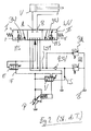
- FIG. 3 shows the circuit diagram of a load-sensing controlled drive system of the invention, for example, designed as an excavator mobile work machine.
- the drive system comprises an adjustable in the delivery volume pump 1, which is operated in the illustrated embodiment in the open circuit and the input side is in communication with a container 2 and the output promotes in a delivery line 3, are connected to the multiple consumers.
- a selected consumer 4 is shown, the control of which is provided as a throttling in intermediate positions control valve 5.
- the consumer 4 has two consumer sides A, B, which are connected by means of consumer lines 6a, 6b to the control valve 5.
- the control valve 5 is further connected by means of a branched from the feed line 3 conveyor branch line 3a to the pump 1 and by means of container branch lines 8a, 8b, which are connected to a container line 8, with the container 2 in connection.
- Trained as a directional valve control valve 5 has a neutral position in which the consumer lines 6a, 6b are shut off.
- a first control position I the consumer side A is connected to the pump 1 and the consumer side B to the container 2.
- a second control position II the consumer side B is connected to the pump 1 and the consumer side A to the container.
- the control valve 5 has in each control position I or II an orifice plate 10a, 10b and is provided with one downstream of the orifice plate 10a, 10b arranged pressure compensator 11 a, 11 b.
- valves control valves for controlling other consumers of the drive system are connected to the delivery line 3, the container line 8 and the load pressure signaling line 21 accordingly.
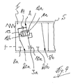
- the construction of the pressure compensator 11 a and 11 b is based on FIG. 4 with the consumer side A associated pressure compensator 11 a described in more detail, in which the control valve 5 is shown in detail in the control position I.
- the downstream of the measuring throttle 10a arranged in the flow path from the delivery branch line 3a to the consumer side A pressure compensator 11a has a flow position 12a and a blocking position 12b.
- the pressure compensator 11a is acted upon by the delivery pressure present downstream of the metering orifice 10a.
- the pressure compensator 11a is acted upon by the highest load pressure of the driven consumers.
- the load pressure signal path of the consumer side A formed by the load pressure alarm branch line 20a begins downstream of the pressure compensator 11a at a branch, at which the load pressure alarm branch line 20a branches off from the flow path of the consumer side A.
- a control line 13 branches off to a control pressure surface of the pressure compensator 11a which acts in the direction of the blocking position 12b.
- a check valve 14 is arranged in the load pressure alarm branch line 20a, which allows the highest load pressure in an operating state in which the consumer side A of the consumer 4, the on the load side A pending load pressure is reported in the load pressure signaling line 21, and in an operating state in which another consumer performs the highest load pressure, the loading of the weigher 11a in the direction of the blocking position 12b of the upcoming in the load pressure signaling line 21 highest load pressure of the other Consumer ensures.
- the pump 1 has to control the flow rate Actuator 25, for example, an inclination adjustable swash plate of an axial piston pump, which is operatively connected to the actuation with an actuating piston device 26.
- the adjusting piston device 26 has a control pressure chamber 26a which acts in the direction of an increase in the delivery rate of the pump 1 and which is acted upon by the delivery pressure of the pump 1.
- a guided to the delivery line 3 control line 3b is provided.
- a spring device 27 can continue to act.
- the application in the direction of a reduction in the flow rate of the pump 1 acting control pressure chamber 26 b of the control piston line 26 is controlled by means of a demand flow control valve 30.
- the control pressure chamber 26b is connected to the delivery line of the pump 1 and thus acted upon by the delivery pressure of the pump 1.
- the demand flow control valve 30 is acted upon by the delivery pressure of the pump 1 in the direction of the second control position 30b.
- the demand flow control valve 30 is acted upon by the highest load pressure of the controlled consumers present in the load pressure signaling line 21 and a spring device 31 whose bias corresponds to the control pressure difference of the load sensing system.
- the drive system is provided for maximum consumer pressure protection with a Schollabschneidung 40, which is formed by a designed as a pressure relief valve, the load pressure signaling line 21 associated Schotikabschneidevent 41.
- the main pressure cut-off valve 41 is connected on the input side to the load pressure signaling line 21 and is connected on the output side to the container 2.
- the Haupttikabschneideventil 41 is acted upon by the in the load pressure signaling line 21 pending, the demand flow control valve 30 controlling the highest load pressure of the driven consumers in the direction of an open position.
- a spring device 42 set to the maximum permissible load pressure acts on the main pressure cut-off valve 41.
- the main pressure cut-off valve 41 During operation of the drive system, upon reaching the maximum permissible load pressure, the main pressure cut-off valve 41 responds and limits the load pressure in the load-pressure-signaling line 21 to the value set on the spring device 42. In response to the Hauptlichabschneideventils 41 in conjunction with the demand flow control valve 30, the flow rate of the pump 1 is limited or reduced, whereby the pressure for all consumers is limited to a maximum value.
- the Haupttikabschneideventil 41 thus represents a system insurance to limit the maximum consumer pressure.
- a single-pressure protection and thus a separate consumer pressure protection with an individual and separate pressure cut-off 50 are provided on the selected consumer 4, which only acts on a single consumer side A.
- the pressure cut-off 50 uses the already existing, the consumer side A associated pressure compensator 11a of the control valve 5 and applied to the pressure cut the pressure compensator 11a in the direction of the blocking position 12b.
- the pressure cut-off comprises a pressure cut-off valve 51 in the load pressure alarm branch line 20a and thus in the load pressure signal path of the consumer side A to be protected, which operates as a pilot valve for actuating the pressure scale 11a associated with the consumer side A.
- the load pressure signal path of the load side A is in this case limited by the tap of the load pressure of the load side A on the control valve 5 and the connection of the load pressure alarm branch line 20a to the load pressure signaling line 21.
- the pressure cut-off valve 51 is designed as a control valve throttling in intermediate positions, which has a flow-through position 51 a and a pressure cut-off position 51 b.
- the load pressure alarm branch line 20a of the consumer side A is fully opened.
- a guided to the pressure cut valve 51 pressure signal line 52, which is in the present embodiment with the delivery line 3 of the pump 1 in communication is shut off in the flow position 51a.
- the pressure signal line 52 is connected to the portion of the load pressure alarm branch line 20 a, which is guided to the acting in the direction of the blocking position 12 b control pressure surface of the consumer side A associated pressure compensator 11 a.
- the pressure compensator 11a is acted upon by the pending in the pressure signal line 52 pressure signal, in the illustrated embodiment of the delivery pressure of the pump 1, in the direction of the blocking position 12b.
- the connection of the load-pressure alarm branch line 20 a to the load-pressure-signaling line 21 is interrupted and shut off.
- the pressure cut-off valve 51 is acted upon in the direction of the pressure cut-off position 51 b by the load side pressure at the consumer side A to be secured.
- a signal line 53 branching off from the consumer line 6a is led to a corresponding control surface of the pressure cutoff valve 51.
- the pressure cut-off valve 51 is acted upon by a setting device 54 which predetermines the consumer protection pressure to be protected on the consumer side A.
- the adjusting device 54 is formed by a spring device, in particular an adjustable spring.
- a not-shown changing means may be provided which allows an electrical or hydraulic or electro-hydraulic adjustment of Disabtechnischstikes on the pressure cut valve 51.
- the spring side of the Druckabschneideventils 51 is relieved by means of a discharge line 55 to the container 2.
- the pressure cut valve 51 is in the flow position 51 a , In the flow position 51 a and thus open load pressure branch line 21 a of the consumer side A pending load pressure of the consumer 5 - if the consumer 4 in the control of several consumers the highest load pressure leads - unhindered by the tap on the control valve 5 to the load pressure signaling line 21 for controlling the Pump 1 and be led to the pressure compensators on the control valves of other consumers. If another consumer leads the highest load pressure, the highest load pressure of the further consumer present in the load pressure signaling line 21 can be forwarded via the pressure cutoff valve 51 to the pressure compensator 11a (control line 13) of the consumer side A in the opposite flow direction.
- the pressure cut valve 55 is applied in the direction of Druckabschneidegna 51 b, in which the pressure signal formed by the delivery pressure of the pump 1 in the pressure signal line 52 via the load pressure alarm branch line 20a and the control line 13 at the in the direction of the blocking position 12b acting control pressure surface of the consumer side A associated pressure compensator 11a is present.
- the Druckabschneidegna 51 b thus working as a pilot valve pressure cut valve 51 controls the pressure compensator 11 a in the closing direction, whereby the pressure on the consumer side A of the selected consumer is secured to the set Bisab Anlagenstik.
- only a separate pressure cut-off 50 according to the invention is provided on the consumer side A of the selected consumer 4 with the pressure cut-off valve 51 in the load pressure alarm branch line 20a.
- the inventive individual and separate pressure cut 50 of a consumer side A with a pressure cut valve 51 in the load pressure signal path of the corresponding consumer side A to be protected as a pilot valve for the consumer side A associated pressure compensator 11a of the control valve 5 has a number of advantages.
- each consumer side can be individually and independently of the other at a selected consumer 4 Consumer side are secured and a Craftstik for each consumer side individually and independently of the other consumer side or the system protection on a main pressure cut-off valve 40 are set.
- the pressure cut-off according to the invention with the pressure cutoff valves 51 can be used and used on each consumer side of a selected consumer independently of the other consumer side.
- each consumer side can be set independently of the remainder system in the consumer protection pressure.
- the consumer protection pressure at the pressure cut-off valve 51 operating as a pilot valve can be changed and adjusted in a simple manner.
- the pressure cut-off 50 according to the invention is effective in the load pressure signal path of the corresponding consumer side.
- the pressure cut-off 50 according to the invention can be easily supplemented by appropriate pressure cut-off valves 51 designed as pilot valves and retrofitted to existing control valves 5.
- the pressure cutoff valves 51 designed as pilot valves have a compact design and allow installation in the valve housing of the control valve 5.
- the separate Druckabschneidung invention is associated with low production costs.
- the separate pressure cut 50 according to the invention caused by the elimination of an inlet pressure compensator according to the FIG. 2 for a separate pressure cut-off at a selected consumer, no leakage line in the main flow of the pump 1.
- Another advantage of the separate pressure protection according to the invention is that due to the nature of the pressure protection in the load pressure signal path 20a an associated consumer side A neither from the consumer pressure A nor from the load pressure signal path 20a pressure fluid is removed and thus no Falsification of the load pressure signal or unwanted lowering of the consumer occurs. At the pressure compensator 11 a occur in the pressure cut only small losses.
- the Kleinnikabschneideventil 41 secures the consumer side B of the selected consumer 4 and the remaining consumers.
- the advantage of the inventive separate Druckabschneidung 50 for a consumer side A is that the consumer side A flowing volume flow, for example, in a so-called blocking point operation, in which the consumer 4 is at a stop, is reduced to almost 0 l / min and only internal leakage to the consumer 4 must be covered, resulting in virtually no power dissipation occurs during the pressure cut.
Landscapes
- Engineering & Computer Science (AREA)
- General Engineering & Computer Science (AREA)
- Mining & Mineral Resources (AREA)
- Civil Engineering (AREA)
- Structural Engineering (AREA)
- Physics & Mathematics (AREA)
- Fluid Mechanics (AREA)
- Mechanical Engineering (AREA)
- Fluid-Pressure Circuits (AREA)
Applications Claiming Priority (1)
| Application Number | Priority Date | Filing Date | Title |
|---|---|---|---|
| DE102010048893A DE102010048893A1 (de) | 2010-10-19 | 2010-10-19 | Load-Sensing geregeltes hydrostatisches Antriebssystem |
Publications (4)
| Publication Number | Publication Date |
|---|---|
| EP2444360A2 true EP2444360A2 (fr) | 2012-04-25 |
| EP2444360A3 EP2444360A3 (fr) | 2014-10-29 |
| EP2444360B1 EP2444360B1 (fr) | 2017-05-03 |
| EP2444360B9 EP2444360B9 (fr) | 2017-08-16 |
Family
ID=44719607
Family Applications (1)
| Application Number | Title | Priority Date | Filing Date |
|---|---|---|---|
| EP11183410.7A Active EP2444360B9 (fr) | 2010-10-19 | 2011-09-30 | Système d'entraînement hydrostatique réglé par détection de charge |
Country Status (3)
| Country | Link |
|---|---|
| EP (1) | EP2444360B9 (fr) |
| CN (1) | CN102562694B (fr) |
| DE (1) | DE102010048893A1 (fr) |
Families Citing this family (6)
| Publication number | Priority date | Publication date | Assignee | Title |
|---|---|---|---|---|
| DE102012110070A1 (de) * | 2012-10-22 | 2014-04-24 | Linde Hydraulics Gmbh & Co. Kg | Hydrostatisches Antriebssystem |
| DE102014102336A1 (de) * | 2014-02-24 | 2015-08-27 | Linde Hydraulics Gmbh & Co. Kg | Steuerventileinrichtung mit einer Schwimmstellung |
| DE102014107231B4 (de) | 2014-05-22 | 2024-12-19 | Linde Hydraulics Gmbh & Co. Kg | Bedarfsstromgeregeltes hydrostatisches Antriebssystem |
| DE102015116761A1 (de) * | 2015-10-02 | 2017-04-06 | Linde Hydraulics Gmbh & Co. Kg | Hydraulisches Konstantdrucksystem einer mobile Arbeitsmaschine |
| DE102016117206A1 (de) * | 2016-09-13 | 2018-03-15 | Linde Hydraulics Gmbh & Co. Kg | Load-Sensing Antriebssystem |
| CN109441906B (zh) * | 2018-12-27 | 2020-05-08 | 上海航天控制技术研究所 | 一种电液比例负载敏感泵及泵阀联合控制伺服系统 |
Citations (2)
| Publication number | Priority date | Publication date | Assignee | Title |
|---|---|---|---|---|
| DE102008054084A1 (de) | 2008-07-25 | 2010-01-28 | Linde Material Handling Gmbh | Hydrostatisches Antriebssystem |
| DE102008049076A1 (de) | 2008-09-26 | 2010-04-01 | Linde Material Handling Gmbh | Mobile Arbeitsmaschine, insbesondere Flurförderzeug |
Family Cites Families (6)
| Publication number | Priority date | Publication date | Assignee | Title |
|---|---|---|---|---|
| DE3546336A1 (de) * | 1985-12-30 | 1987-07-02 | Rexroth Mannesmann Gmbh | Steueranordnung fuer mindestens zwei von mindestens einer pumpe gespeiste hydraulische verbraucher |
| DE4235709A1 (de) * | 1992-10-22 | 1994-04-28 | Linde Ag | Hydrostatisches Antriebssystem |
| JP3286147B2 (ja) * | 1996-02-08 | 2002-05-27 | 株式会社クボタ | 建機の油圧回路 |
| US5941155A (en) * | 1996-11-20 | 1999-08-24 | Kabushiki Kaisha Kobe Seiko Sho | Hydraulic motor control system |
| JPH1130205A (ja) * | 1997-07-11 | 1999-02-02 | Hitachi Constr Mach Co Ltd | 油圧回路装置及び分流補償付き方向切換弁装置 |
| JP3240286B2 (ja) * | 1998-04-28 | 2001-12-17 | 東芝機械株式会社 | 油圧システム |
-
2010
- 2010-10-19 DE DE102010048893A patent/DE102010048893A1/de not_active Withdrawn
-
2011
- 2011-09-30 EP EP11183410.7A patent/EP2444360B9/fr active Active
- 2011-10-19 CN CN201110327247.0A patent/CN102562694B/zh not_active Expired - Fee Related
Patent Citations (2)
| Publication number | Priority date | Publication date | Assignee | Title |
|---|---|---|---|---|
| DE102008054084A1 (de) | 2008-07-25 | 2010-01-28 | Linde Material Handling Gmbh | Hydrostatisches Antriebssystem |
| DE102008049076A1 (de) | 2008-09-26 | 2010-04-01 | Linde Material Handling Gmbh | Mobile Arbeitsmaschine, insbesondere Flurförderzeug |
Also Published As
| Publication number | Publication date |
|---|---|
| EP2444360B9 (fr) | 2017-08-16 |
| CN102562694B (zh) | 2016-06-01 |
| DE102010048893A1 (de) | 2012-04-19 |
| EP2444360B1 (fr) | 2017-05-03 |
| EP2444360A3 (fr) | 2014-10-29 |
| CN102562694A (zh) | 2012-07-11 |
Similar Documents
| Publication | Publication Date | Title |
|---|---|---|
| EP1092095B2 (fr) | Circuit hydraulique | |
| EP0499694B1 (fr) | Dispositif de commande hydraulique | |
| EP2225470B1 (fr) | Système de distributeur | |
| DE102004012382B4 (de) | Hydraulische Anordnung | |
| EP1450048A1 (fr) | Agencement de vanne | |
| EP2444360B1 (fr) | Système d'entraînement hydrostatique réglé par détection de charge | |
| EP2863068A1 (fr) | Bloc de soupapes avec système de vannes | |
| DE19831595B4 (de) | Hydraulische Schaltung | |
| EP2142808B1 (fr) | Ensemble de commande hydraulique | |
| DE19834955A1 (de) | Hydrostatisches Antriebssystem | |
| EP2636908A2 (fr) | Agencement de commande | |
| EP2667038A2 (fr) | Agencement de circuit hydraulique | |
| WO2008151727A2 (fr) | Ensemble de commande à fonction de protection contre la rupture de tuyaux | |
| DE102011107218B4 (de) | Hydrostatisches Antriebssystem | |
| EP2910796B1 (fr) | Assemblage avec un dispositif de vanne de commande à position flottante | |
| EP2157320B1 (fr) | Commande hydraulique pour un moteur hydraulique | |
| DE102005059238B4 (de) | Steuerventileinrichtung zur Steuerung eines Verbrauchers | |
| EP2657178B9 (fr) | Installation hydraulique d'une machine de travail mobile | |
| DE10254605B4 (de) | Steuerventileinrichtung | |
| DE102005059239B4 (de) | Ventileinrichtung | |
| DE102007034746B4 (de) | Hydrostatisches Antriebssystem | |
| DE10149791A1 (de) | Steuerventileinrichtung | |
| EP1954949B1 (fr) | Dispositif hydraulique de commande | |
| DE102016105159A1 (de) | Hydrauliksystem eines land- oder bauwirtschaftlich nutzbaren Fahrzeugs | |
| EP2980006B1 (fr) | Installation hydraulique d'une machine de travail mobile, notamment d'un chariot de manutention |
Legal Events
| Date | Code | Title | Description |
|---|---|---|---|
| AK | Designated contracting states |
Kind code of ref document: A2 Designated state(s): AL AT BE BG CH CY CZ DE DK EE ES FI FR GB GR HR HU IE IS IT LI LT LU LV MC MK MT NL NO PL PT RO RS SE SI SK SM TR |
|
| AX | Request for extension of the european patent |
Extension state: BA ME |
|
| PUAI | Public reference made under article 153(3) epc to a published international application that has entered the european phase |
Free format text: ORIGINAL CODE: 0009012 |
|
| RIN1 | Information on inventor provided before grant (corrected) |
Inventor name: FELLENBERG, LUDWIG Inventor name: SCHOENFELDER, MARKUS |
|
| RIN1 | Information on inventor provided before grant (corrected) |
Inventor name: SCHOENFELDER, MARKUS Inventor name: FELLENBERG, LUDWIG |
|
| RAP1 | Party data changed (applicant data changed or rights of an application transferred) |
Owner name: LINDE HYDRAULICS GMBH & CO. KG |
|
| PUAL | Search report despatched |
Free format text: ORIGINAL CODE: 0009013 |
|
| AK | Designated contracting states |
Kind code of ref document: A3 Designated state(s): AL AT BE BG CH CY CZ DE DK EE ES FI FR GB GR HR HU IE IS IT LI LT LU LV MC MK MT NL NO PL PT RO RS SE SI SK SM TR |
|
| AX | Request for extension of the european patent |
Extension state: BA ME |
|
| RIC1 | Information provided on ipc code assigned before grant |
Ipc: E02F 9/22 20060101ALI20140919BHEP Ipc: B66F 9/22 20060101AFI20140919BHEP Ipc: F15B 11/05 20060101ALI20140919BHEP |
|
| 17P | Request for examination filed |
Effective date: 20150413 |
|
| RBV | Designated contracting states (corrected) |
Designated state(s): AL AT BE BG CH CY CZ DE DK EE ES FI FR GB GR HR HU IE IS IT LI LT LU LV MC MK MT NL NO PL PT RO RS SE SI SK SM TR |
|
| GRAP | Despatch of communication of intention to grant a patent |
Free format text: ORIGINAL CODE: EPIDOSNIGR1 |
|
| STAA | Information on the status of an ep patent application or granted ep patent |
Free format text: STATUS: GRANT OF PATENT IS INTENDED |
|
| INTG | Intention to grant announced |
Effective date: 20170118 |
|
| GRAS | Grant fee paid |
Free format text: ORIGINAL CODE: EPIDOSNIGR3 |
|
| GRAA | (expected) grant |
Free format text: ORIGINAL CODE: 0009210 |
|
| STAA | Information on the status of an ep patent application or granted ep patent |
Free format text: STATUS: THE PATENT HAS BEEN GRANTED |
|
| AK | Designated contracting states |
Kind code of ref document: B1 Designated state(s): AL AT BE BG CH CY CZ DE DK EE ES FI FR GB GR HR HU IE IS IT LI LT LU LV MC MK MT NL NO PL PT RO RS SE SI SK SM TR |
|
| REG | Reference to a national code |
Ref country code: GB Ref legal event code: FG4D Free format text: NOT ENGLISH |
|
| REG | Reference to a national code |
Ref country code: AT Ref legal event code: REF Ref document number: 889742 Country of ref document: AT Kind code of ref document: T Effective date: 20170515 Ref country code: CH Ref legal event code: EP |
|
| REG | Reference to a national code |
Ref country code: IE Ref legal event code: FG4D Free format text: LANGUAGE OF EP DOCUMENT: GERMAN |
|
| REG | Reference to a national code |
Ref country code: DE Ref legal event code: R096 Ref document number: 502011012149 Country of ref document: DE |
|
| REG | Reference to a national code |
Ref country code: NL Ref legal event code: MP Effective date: 20170503 |
|
| REG | Reference to a national code |
Ref country code: LT Ref legal event code: MG4D Ref country code: FR Ref legal event code: PLFP Year of fee payment: 7 |
|
| PG25 | Lapsed in a contracting state [announced via postgrant information from national office to epo] |
Ref country code: ES Free format text: LAPSE BECAUSE OF FAILURE TO SUBMIT A TRANSLATION OF THE DESCRIPTION OR TO PAY THE FEE WITHIN THE PRESCRIBED TIME-LIMIT Effective date: 20170503 Ref country code: FI Free format text: LAPSE BECAUSE OF FAILURE TO SUBMIT A TRANSLATION OF THE DESCRIPTION OR TO PAY THE FEE WITHIN THE PRESCRIBED TIME-LIMIT Effective date: 20170503 Ref country code: GR Free format text: LAPSE BECAUSE OF FAILURE TO SUBMIT A TRANSLATION OF THE DESCRIPTION OR TO PAY THE FEE WITHIN THE PRESCRIBED TIME-LIMIT Effective date: 20170804 Ref country code: LT Free format text: LAPSE BECAUSE OF FAILURE TO SUBMIT A TRANSLATION OF THE DESCRIPTION OR TO PAY THE FEE WITHIN THE PRESCRIBED TIME-LIMIT Effective date: 20170503 Ref country code: HR Free format text: LAPSE BECAUSE OF FAILURE TO SUBMIT A TRANSLATION OF THE DESCRIPTION OR TO PAY THE FEE WITHIN THE PRESCRIBED TIME-LIMIT Effective date: 20170503 Ref country code: NO Free format text: LAPSE BECAUSE OF FAILURE TO SUBMIT A TRANSLATION OF THE DESCRIPTION OR TO PAY THE FEE WITHIN THE PRESCRIBED TIME-LIMIT Effective date: 20170803 |
|
| PG25 | Lapsed in a contracting state [announced via postgrant information from national office to epo] |
Ref country code: PL Free format text: LAPSE BECAUSE OF FAILURE TO SUBMIT A TRANSLATION OF THE DESCRIPTION OR TO PAY THE FEE WITHIN THE PRESCRIBED TIME-LIMIT Effective date: 20170503 Ref country code: SE Free format text: LAPSE BECAUSE OF FAILURE TO SUBMIT A TRANSLATION OF THE DESCRIPTION OR TO PAY THE FEE WITHIN THE PRESCRIBED TIME-LIMIT Effective date: 20170503 Ref country code: BG Free format text: LAPSE BECAUSE OF FAILURE TO SUBMIT A TRANSLATION OF THE DESCRIPTION OR TO PAY THE FEE WITHIN THE PRESCRIBED TIME-LIMIT Effective date: 20170803 Ref country code: RS Free format text: LAPSE BECAUSE OF FAILURE TO SUBMIT A TRANSLATION OF THE DESCRIPTION OR TO PAY THE FEE WITHIN THE PRESCRIBED TIME-LIMIT Effective date: 20170503 Ref country code: IS Free format text: LAPSE BECAUSE OF FAILURE TO SUBMIT A TRANSLATION OF THE DESCRIPTION OR TO PAY THE FEE WITHIN THE PRESCRIBED TIME-LIMIT Effective date: 20170903 Ref country code: LV Free format text: LAPSE BECAUSE OF FAILURE TO SUBMIT A TRANSLATION OF THE DESCRIPTION OR TO PAY THE FEE WITHIN THE PRESCRIBED TIME-LIMIT Effective date: 20170503 Ref country code: NL Free format text: LAPSE BECAUSE OF FAILURE TO SUBMIT A TRANSLATION OF THE DESCRIPTION OR TO PAY THE FEE WITHIN THE PRESCRIBED TIME-LIMIT Effective date: 20170503 |
|
| PG25 | Lapsed in a contracting state [announced via postgrant information from national office to epo] |
Ref country code: DK Free format text: LAPSE BECAUSE OF FAILURE TO SUBMIT A TRANSLATION OF THE DESCRIPTION OR TO PAY THE FEE WITHIN THE PRESCRIBED TIME-LIMIT Effective date: 20170503 Ref country code: CZ Free format text: LAPSE BECAUSE OF FAILURE TO SUBMIT A TRANSLATION OF THE DESCRIPTION OR TO PAY THE FEE WITHIN THE PRESCRIBED TIME-LIMIT Effective date: 20170503 Ref country code: SK Free format text: LAPSE BECAUSE OF FAILURE TO SUBMIT A TRANSLATION OF THE DESCRIPTION OR TO PAY THE FEE WITHIN THE PRESCRIBED TIME-LIMIT Effective date: 20170503 Ref country code: EE Free format text: LAPSE BECAUSE OF FAILURE TO SUBMIT A TRANSLATION OF THE DESCRIPTION OR TO PAY THE FEE WITHIN THE PRESCRIBED TIME-LIMIT Effective date: 20170503 Ref country code: RO Free format text: LAPSE BECAUSE OF FAILURE TO SUBMIT A TRANSLATION OF THE DESCRIPTION OR TO PAY THE FEE WITHIN THE PRESCRIBED TIME-LIMIT Effective date: 20170503 |
|
| REG | Reference to a national code |
Ref country code: DE Ref legal event code: R097 Ref document number: 502011012149 Country of ref document: DE |
|
| PG25 | Lapsed in a contracting state [announced via postgrant information from national office to epo] |
Ref country code: SM Free format text: LAPSE BECAUSE OF FAILURE TO SUBMIT A TRANSLATION OF THE DESCRIPTION OR TO PAY THE FEE WITHIN THE PRESCRIBED TIME-LIMIT Effective date: 20170503 Ref country code: IT Free format text: LAPSE BECAUSE OF FAILURE TO SUBMIT A TRANSLATION OF THE DESCRIPTION OR TO PAY THE FEE WITHIN THE PRESCRIBED TIME-LIMIT Effective date: 20170503 |
|
| PLBE | No opposition filed within time limit |
Free format text: ORIGINAL CODE: 0009261 |
|
| STAA | Information on the status of an ep patent application or granted ep patent |
Free format text: STATUS: NO OPPOSITION FILED WITHIN TIME LIMIT |
|
| 26N | No opposition filed |
Effective date: 20180206 |
|
| REG | Reference to a national code |
Ref country code: CH Ref legal event code: PL |
|
| PG25 | Lapsed in a contracting state [announced via postgrant information from national office to epo] |
Ref country code: SI Free format text: LAPSE BECAUSE OF FAILURE TO SUBMIT A TRANSLATION OF THE DESCRIPTION OR TO PAY THE FEE WITHIN THE PRESCRIBED TIME-LIMIT Effective date: 20170503 Ref country code: MC Free format text: LAPSE BECAUSE OF FAILURE TO SUBMIT A TRANSLATION OF THE DESCRIPTION OR TO PAY THE FEE WITHIN THE PRESCRIBED TIME-LIMIT Effective date: 20170503 |
|
| REG | Reference to a national code |
Ref country code: IE Ref legal event code: MM4A |
|
| REG | Reference to a national code |
Ref country code: BE Ref legal event code: MM Effective date: 20170930 |
|
| PG25 | Lapsed in a contracting state [announced via postgrant information from national office to epo] |
Ref country code: LU Free format text: LAPSE BECAUSE OF NON-PAYMENT OF DUE FEES Effective date: 20170930 |
|
| PG25 | Lapsed in a contracting state [announced via postgrant information from national office to epo] |
Ref country code: CH Free format text: LAPSE BECAUSE OF NON-PAYMENT OF DUE FEES Effective date: 20170930 Ref country code: LI Free format text: LAPSE BECAUSE OF NON-PAYMENT OF DUE FEES Effective date: 20170930 Ref country code: IE Free format text: LAPSE BECAUSE OF NON-PAYMENT OF DUE FEES Effective date: 20170930 |
|
| PG25 | Lapsed in a contracting state [announced via postgrant information from national office to epo] |
Ref country code: BE Free format text: LAPSE BECAUSE OF NON-PAYMENT OF DUE FEES Effective date: 20170930 |
|
| REG | Reference to a national code |
Ref country code: FR Ref legal event code: PLFP Year of fee payment: 8 |
|
| PG25 | Lapsed in a contracting state [announced via postgrant information from national office to epo] |
Ref country code: MT Free format text: LAPSE BECAUSE OF FAILURE TO SUBMIT A TRANSLATION OF THE DESCRIPTION OR TO PAY THE FEE WITHIN THE PRESCRIBED TIME-LIMIT Effective date: 20170503 |
|
| REG | Reference to a national code |
Ref country code: AT Ref legal event code: MM01 Ref document number: 889742 Country of ref document: AT Kind code of ref document: T Effective date: 20170930 |
|
| PG25 | Lapsed in a contracting state [announced via postgrant information from national office to epo] |
Ref country code: AT Free format text: LAPSE BECAUSE OF NON-PAYMENT OF DUE FEES Effective date: 20170930 |
|
| PG25 | Lapsed in a contracting state [announced via postgrant information from national office to epo] |
Ref country code: HU Free format text: LAPSE BECAUSE OF FAILURE TO SUBMIT A TRANSLATION OF THE DESCRIPTION OR TO PAY THE FEE WITHIN THE PRESCRIBED TIME-LIMIT; INVALID AB INITIO Effective date: 20110930 |
|
| PG25 | Lapsed in a contracting state [announced via postgrant information from national office to epo] |
Ref country code: CY Free format text: LAPSE BECAUSE OF NON-PAYMENT OF DUE FEES Effective date: 20170503 |
|
| PGFP | Annual fee paid to national office [announced via postgrant information from national office to epo] |
Ref country code: FR Payment date: 20190923 Year of fee payment: 9 |
|
| PG25 | Lapsed in a contracting state [announced via postgrant information from national office to epo] |
Ref country code: MK Free format text: LAPSE BECAUSE OF FAILURE TO SUBMIT A TRANSLATION OF THE DESCRIPTION OR TO PAY THE FEE WITHIN THE PRESCRIBED TIME-LIMIT Effective date: 20170503 |
|
| PGFP | Annual fee paid to national office [announced via postgrant information from national office to epo] |
Ref country code: GB Payment date: 20190924 Year of fee payment: 9 |
|
| PG25 | Lapsed in a contracting state [announced via postgrant information from national office to epo] |
Ref country code: TR Free format text: LAPSE BECAUSE OF FAILURE TO SUBMIT A TRANSLATION OF THE DESCRIPTION OR TO PAY THE FEE WITHIN THE PRESCRIBED TIME-LIMIT Effective date: 20170503 |
|
| PG25 | Lapsed in a contracting state [announced via postgrant information from national office to epo] |
Ref country code: PT Free format text: LAPSE BECAUSE OF FAILURE TO SUBMIT A TRANSLATION OF THE DESCRIPTION OR TO PAY THE FEE WITHIN THE PRESCRIBED TIME-LIMIT Effective date: 20170503 |
|
| PG25 | Lapsed in a contracting state [announced via postgrant information from national office to epo] |
Ref country code: AL Free format text: LAPSE BECAUSE OF FAILURE TO SUBMIT A TRANSLATION OF THE DESCRIPTION OR TO PAY THE FEE WITHIN THE PRESCRIBED TIME-LIMIT Effective date: 20170503 |
|
| GBPC | Gb: european patent ceased through non-payment of renewal fee |
Effective date: 20200930 |
|
| PG25 | Lapsed in a contracting state [announced via postgrant information from national office to epo] |
Ref country code: FR Free format text: LAPSE BECAUSE OF NON-PAYMENT OF DUE FEES Effective date: 20200930 |
|
| PG25 | Lapsed in a contracting state [announced via postgrant information from national office to epo] |
Ref country code: GB Free format text: LAPSE BECAUSE OF NON-PAYMENT OF DUE FEES Effective date: 20200930 |
|
| P01 | Opt-out of the competence of the unified patent court (upc) registered |
Effective date: 20230514 |
|
| PGFP | Annual fee paid to national office [announced via postgrant information from national office to epo] |
Ref country code: DE Payment date: 20240919 Year of fee payment: 14 |
|
| REG | Reference to a national code |
Ref country code: DE Ref legal event code: R081 Ref document number: 502011012149 Country of ref document: DE Owner name: LHY POWERTRAIN GMBH & CO. KG, DE Free format text: FORMER OWNER: LINDE HYDRAULICS GMBH & CO. KG, 63743 ASCHAFFENBURG, DE |