EP2444568A2 - Elément de construction - Google Patents
Elément de construction Download PDFInfo
- Publication number
- EP2444568A2 EP2444568A2 EP11008540A EP11008540A EP2444568A2 EP 2444568 A2 EP2444568 A2 EP 2444568A2 EP 11008540 A EP11008540 A EP 11008540A EP 11008540 A EP11008540 A EP 11008540A EP 2444568 A2 EP2444568 A2 EP 2444568A2
- Authority
- EP
- European Patent Office
- Prior art keywords
- outer shell
- component
- panels
- shells
- shell
- Prior art date
- Legal status (The legal status is an assumption and is not a legal conclusion. Google has not performed a legal analysis and makes no representation as to the accuracy of the status listed.)
- Withdrawn
Links
- 238000004519 manufacturing process Methods 0.000 claims description 23
- 238000000034 method Methods 0.000 claims description 12
- 239000004033 plastic Substances 0.000 claims description 11
- 229920003023 plastic Polymers 0.000 claims description 11
- 238000005304 joining Methods 0.000 claims description 8
- 238000005253 cladding Methods 0.000 claims description 4
- 239000008187 granular material Substances 0.000 claims description 4
- 238000002844 melting Methods 0.000 claims description 2
- 230000008018 melting Effects 0.000 claims description 2
- 230000008878 coupling Effects 0.000 description 22
- 238000010168 coupling process Methods 0.000 description 22
- 238000005859 coupling reaction Methods 0.000 description 22
- 230000008901 benefit Effects 0.000 description 7
- 238000001125 extrusion Methods 0.000 description 6
- 241000264877 Hippospongia communis Species 0.000 description 5
- 238000010276 construction Methods 0.000 description 5
- 238000009413 insulation Methods 0.000 description 5
- 239000000463 material Substances 0.000 description 5
- 239000004417 polycarbonate Substances 0.000 description 5
- 229920000515 polycarbonate Polymers 0.000 description 5
- 230000008569 process Effects 0.000 description 5
- 210000003746 feather Anatomy 0.000 description 4
- 238000007493 shaping process Methods 0.000 description 4
- 229920005830 Polyurethane Foam Polymers 0.000 description 2
- 230000006835 compression Effects 0.000 description 2
- 238000007906 compression Methods 0.000 description 2
- 238000009434 installation Methods 0.000 description 2
- 239000011496 polyurethane foam Substances 0.000 description 2
- 230000009471 action Effects 0.000 description 1
- 230000006978 adaptation Effects 0.000 description 1
- XAGFODPZIPBFFR-UHFFFAOYSA-N aluminium Chemical compound [Al] XAGFODPZIPBFFR-UHFFFAOYSA-N 0.000 description 1
- 229910052782 aluminium Inorganic materials 0.000 description 1
- 230000015572 biosynthetic process Effects 0.000 description 1
- 238000007664 blowing Methods 0.000 description 1
- 230000008859 change Effects 0.000 description 1
- 238000006243 chemical reaction Methods 0.000 description 1
- 239000011248 coating agent Substances 0.000 description 1
- 238000000576 coating method Methods 0.000 description 1
- 230000001419 dependent effect Effects 0.000 description 1
- 238000005516 engineering process Methods 0.000 description 1
- 238000005286 illumination Methods 0.000 description 1
- 230000000737 periodic effect Effects 0.000 description 1
- 238000002360 preparation method Methods 0.000 description 1
- 238000003825 pressing Methods 0.000 description 1
- 230000000284 resting effect Effects 0.000 description 1
- 239000000758 substrate Substances 0.000 description 1
- 239000006228 supernatant Substances 0.000 description 1
- 238000009423 ventilation Methods 0.000 description 1
Images






Classifications
-
- E—FIXED CONSTRUCTIONS
- E04—BUILDING
- E04F—FINISHING WORK ON BUILDINGS, e.g. STAIRS, FLOORS
- E04F13/00—Coverings or linings, e.g. for walls or ceilings
- E04F13/07—Coverings or linings, e.g. for walls or ceilings composed of covering or lining elements; Sub-structures therefor; Fastening means therefor
- E04F13/08—Coverings or linings, e.g. for walls or ceilings composed of covering or lining elements; Sub-structures therefor; Fastening means therefor composed of a plurality of similar covering or lining elements
- E04F13/18—Coverings or linings, e.g. for walls or ceilings composed of covering or lining elements; Sub-structures therefor; Fastening means therefor composed of a plurality of similar covering or lining elements of organic plastics with or without reinforcements or filling materials or with an outer layer of organic plastics with or without reinforcements or filling materials; plastic tiles
-
- E—FIXED CONSTRUCTIONS
- E04—BUILDING
- E04C—STRUCTURAL ELEMENTS; BUILDING MATERIALS
- E04C2/00—Building elements of relatively thin form for the construction of parts of buildings, e.g. sheet materials, slabs, or panels
- E04C2/54—Slab-like translucent elements
- E04C2/543—Hollow multi-walled panels with integrated webs
-
- E—FIXED CONSTRUCTIONS
- E04—BUILDING
- E04D—ROOF COVERINGS; SKY-LIGHTS; GUTTERS; ROOF-WORKING TOOLS
- E04D3/00—Roof covering by making use of flat or curved slabs or stiff sheets
- E04D3/24—Roof covering by making use of flat or curved slabs or stiff sheets with special cross-section, e.g. with corrugations on both sides, with ribs, flanges, or the like
- E04D3/28—Roof covering by making use of flat or curved slabs or stiff sheets with special cross-section, e.g. with corrugations on both sides, with ribs, flanges, or the like of glass or other translucent material
-
- E—FIXED CONSTRUCTIONS
- E04—BUILDING
- E04F—FINISHING WORK ON BUILDINGS, e.g. STAIRS, FLOORS
- E04F13/00—Coverings or linings, e.g. for walls or ceilings
- E04F13/07—Coverings or linings, e.g. for walls or ceilings composed of covering or lining elements; Sub-structures therefor; Fastening means therefor
- E04F13/08—Coverings or linings, e.g. for walls or ceilings composed of covering or lining elements; Sub-structures therefor; Fastening means therefor composed of a plurality of similar covering or lining elements
- E04F13/0871—Coverings or linings, e.g. for walls or ceilings composed of covering or lining elements; Sub-structures therefor; Fastening means therefor composed of a plurality of similar covering or lining elements having an ornamental or specially shaped visible surface
-
- E—FIXED CONSTRUCTIONS
- E04—BUILDING
- E04D—ROOF COVERINGS; SKY-LIGHTS; GUTTERS; ROOF-WORKING TOOLS
- E04D3/00—Roof covering by making use of flat or curved slabs or stiff sheets
- E04D3/24—Roof covering by making use of flat or curved slabs or stiff sheets with special cross-section, e.g. with corrugations on both sides, with ribs, flanges, or the like
- E04D3/28—Roof covering by making use of flat or curved slabs or stiff sheets with special cross-section, e.g. with corrugations on both sides, with ribs, flanges, or the like of glass or other translucent material
- E04D2003/285—Roof covering by making use of flat or curved slabs or stiff sheets with special cross-section, e.g. with corrugations on both sides, with ribs, flanges, or the like of glass or other translucent material with specially profiled marginal portions for connecting purposes
-
- E—FIXED CONSTRUCTIONS
- E04—BUILDING
- E04F—FINISHING WORK ON BUILDINGS, e.g. STAIRS, FLOORS
- E04F2203/00—Specially structured or shaped covering, lining or flooring elements not otherwise provided for
- E04F2203/04—Specially structured or shaped covering, lining or flooring elements not otherwise provided for comprising a plurality of internal elongated cavities arranged in substantially parallel rows
Definitions
- the invention relates to a component and a method for producing the component, in particular for cladding facades or roofing, consisting of an at least two-shell panels, wherein the outer shells are connected to each other via transverse webs or internal structures.
- Generic panels are used for wall or roof surfaces, preferably transparent versions are selected. There are different reasons for this. For example, it is possible to integrate the panels as a roof surface within an existing roof either subsequently or to cover a part of the roof area with the help of panels in order to allow sufficient illumination of the lying below the roof surface premises. This can be advantageous, for example, for factory buildings because this ensures part of the required lighting through the daylight.
- the generic panels is usually made of polycarbonate, which can be processed well and is resistant.
- the production takes place via extruders in the mold, the granules of polycarbonate are melted and pressed through an extruder die, wherein the panels have at least two outer shells and a plurality of transverse webs through which the shells are interconnected.
- the panels have at least two outer shells and a plurality of transverse webs through which the shells are interconnected.
- it is possible to choose a large number of shells which, inter alia, achieves good thermal insulation.
- a particular advantage here is to emphasize that the panels are inexpensive to produce and have significantly less weight than a conventional roofing.
- the panels for covering buildings, for example in the form of a suspended shell or by an immediate attachment to the To equip buildings with a new facade, with the additional opportunity to achieve a pleasing appearance through a color design, so that the appearance of older factory buildings can be embellished.
- the panels are manufactured in a width of 0.3 to 1.50 m, with larger areas can be covered by several side by side and longitudinally arranged one behind the other panels. Wall surfaces can also be covered over the entire surface.
- To connect the panels with one another they can have coupling elements on the longitudinal edges, so that they can be connected to each other in a similar way to a tongue and groove joint.
- the panels are made in a flat corrugated embodiment. With the help of the coupling elements in this case any number of panels can be arranged in parallel side by side and interconnected. The assembly of such panels is carried out in such a way that the coupling elements are connected by compression with each other, wherein the preferred connection direction is in the plane of the panels. However, it is conceivable to use a different connection technology.
- the present invention has for its object to provide a structured component, which can be produced inexpensively.
- a first outer shell has a substantially 2-dimensional plane and the second outer shell has a varying distance from the first outer shell in cross-section to achieve the object.
- the first outer shell may be equipped with a structuring of lower amplitude height, for example by notches, grooves or a corresponding profiling to the second outer shell.
- a structuring of lower amplitude height for example by notches, grooves or a corresponding profiling to the second outer shell.
- a panel can be flush mounted on existing wall or roof surfaces, but at the same time allows a profiled design of the wall or roof surface on the outer side.
- an adaptation to existing roof surfaces take place, which have a similar or identical structuring.
- the distance between the two outer shells may repeat periodically.
- the components produced according to the invention are characterized in that at least one outer shell is structured after the extrusion process by a calibration unit.
- both outer shells have an identical or similar structuring, for example with a different amplitude, preferably on the lower side with a low amplitude and a larger amplitude on the upper side of the component.
- the lower shell has structuring with a low amplitude, it is possible to assemble it with rear ventilation in relation to the substructure. At the same time a mounting on uneven or profiled substructures is facilitated.
- an outer shell, preferably the lower shell level is formed, while only the other outer shell is provided with a structuring.
- the calibration unit has pressure or pressure rollers adapted to the respective geometry. These rollers can be additionally varied by raising or lowering at a distance from the panel, so that a height profile can also be generated in the longitudinal direction.
- the production of the calibration unit is by no means as complex as the production of an extruder nozzle, so that the particular advantage arises that the most varied structures can be produced with one and the same nozzle.
- first outer shell on the bottom (first outer shell) is preferably formed a planar structure, for example, spans a 2-dimensional plane.
- the diametrically opposed outer shell can have a structuring which corresponds to the wishes of the customers.
- a sinusoidal configuration is very common in conventional roofing, so that the panels according to the invention can integrate seamlessly in such a roofing.
- the period length of the repeating structure can be adapted to the needs of the customer at any time by a corresponding shaping in the calibration unit.
- the period length can also be changed by varying the increase of the triangular areas.
- amplitude height may be variable or alternating. The variations are arbitrary.
- this shaping can be additionally provided on the bottom by an identical or possibly different structuring, which, for example, has a different amplitude height.
- the panels may consist only of the two outer shells and the transverse webs connecting them, alternatively it is possible to arrange further inner shells between the two outer shells in order, for example, to increase the thermal insulation value.
- the inner shells it is possible for the inner shells to extend partly parallel to the first outer shell, or for the inner shells to follow, in part, approximately parallel to the second outer shell, and thus for the structured course of the outer shell.
- the longitudinal edges have a maximum distance between the two outer shells. This measure ensures that necessary coupling elements can be formed, the coupling elements themselves being arranged between the two outer shells. At the same time care can be taken by an overlapping supernatant of the second outer shells that they cover each other and thus no moisture gets under the panels.
- such devices are manufactured in a transparent or partially colored opaque embodiment.
- the first and / or second outer shell is colored in such a way that it is either completely opaque or at least partially opaque. With the appropriate coloration can thus be ensured that a passage of light is prevented or a desired transparency is present, which can pass only a portion of the sunlight through the panels.
- the partial opacity refers here either to the entire panel surface or to a strip-like arrangement of different Paneelberelche, which may be alternately translucent or at least partially opaque.
- the second outer shell of the panels has an overlap along at least one longitudinal edge.
- the overlap serves to cover the adjacent panels and thus prevent ingress of moisture.
- Hierbel the overlap may be formed on a longitudinal edge, for example, if several new panels to be laid. If a single panel is to be placed on an existing roofing, it is advisable to provide the overlap on both sides of the longitudinal edges.
- the shape of the overlap should have the structure of the existing roofing, so that it can be placed.
- the shape of the overlap will conform to the shape of the outer shell and be formed, for example, sinusoidal, triangular or trapezoidal.
- the tongue and groove has an approximately elliptical cross-section and is aligned in the direction of the plane formed by the first shell.
- This first type of attachment allows lateral clipping of the adjacent panels and ensures a secure and sufficient grip of the panels.
- the tongue and groove are formed cone-shaped, These are aligned substantially perpendicular to the plane of the first shell.
- This type of attachment allows, for example, a placement of adjacent panels from above, which can be pressed into the existing groove of the underlying panels. In this type of attachment, an easy replacement of the panels is possible because a single panel from the entire bandage can be removed at any time.
- the spring is formed in a peg-shaped manner with at least one, preferably a plurality of latching steps, at least to one side, while the groove is configured in cross-section through a recess with inwardly directed hook-shaped projections.
- the pin can be pressed into the existing groove, while ensuring that different height positions can be taken.
- both the tongue and groove is integrally formed on the panels used, so that the production is made possible in one operation.
- a recess is formed on the longitudinal edges above the first shell, which has a substantially T-shaped cross-section after joining two Paneeie.
- This recess serves to accommodate a suction anchor, which allows attachment to a wall surface or a roof construction.
- the suction anchor is bolted directly to the wall or roof surface, said outwardly having a T-shaped projection which directly into the existing T-shaped recess of two adjacent panels engages.
- the suction arm is slid under the T-shaped projection in the first panel on one side and then the adjoining panel is attached so far that the T-shaped projection engages in the existing half-side recess, but at the same time compression of the two coupling elements, namely the tongue and groove is possible.
- the two coupling elements namely the tongue and groove
- the invention has the object to provide a method by which a structured component can be produced.
- a method for producing a component from a plastic by melting a plastic granulate for pressing out of a die lip of an extruder is provided, so that at least two outer shells are formed, which are interconnected by an internal structure.
- the method is characterized in that a subsequent treatment of the expiring from the extruder component by a calibration unit, by which a deformation of at least one outer shell is made transversely to the longitudinal direction of the component.
- the manufacturing process of panels or hollow discs by means of an extruder is known.
- a plastic granulate is melted and pressed out of the die lip of the extruder, so that a structure is achieved, which is determined by the shape of the die lip.
- multi-layered panels can be produced here, which have at least two outer shells and have an internal structure.
- the inner structure may for example consist of several inner shells or of a honeycomb arrangement or just of transverse webs.
- the production of the extruder, in particular the nozzle body, the nozzle core and the die lip is quite complex and would have to be made extra for each particular form of a panel or hollow chamber disc.
- the new method according to the invention assumes that a calibration unit is used which, for example, is arranged in the immediate vicinity of the nozzle lip so that reworking of the still warm plastic material that has leaked out of the nozzle lip is made possible.
- the calibration unit can in this case be relatively simple and, for example, press the component into a mold, so that the desired structure is achieved on the outer surface of the component.
- the particular advantage of the method is that the calibration unit is quite simple to manufacture and only a replacement of the calibration unit is required to produce a different structure.
- the calibration unit itself can consist, for example, of rollers, roller rollers or sliding surfaces which compress at least one outer shell and at least one part of the inner structure in the heated state insofar as the desired shape is obtained.
- the rollers, rollers or sliding surfaces can be raised and lowered periodically during the manufacturing process in order to make a deformation of at least one outer shell and at least partially of the inner structure in the longitudinal direction of the component.
- the rollers, rollers or sliding surfaces are fixed in a fixed height, only the outer shell and optionally the internal structure in the transverse direction are influenced to the direction of production of the device.
- a structure can be additionally generated in the longitudinal direction, which can optionally also in combined form, that is, in the transverse and longitudinal direction, can be generated.
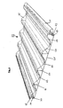
- FIG. 1 shows in a perspective view a first embodiment of a component 1, which consists of an extruded panel
- the panels are manufactured in an extrusion process, wherein a lower outer shell 3 and an upper outer shell 4 are formed.
- transverse webs 5, 6 are provided which have 4 different heights corresponding to the profiling of the upper shell.
- the position of the transverse webs 5, 6 can be chosen arbitrarily.
- coupling elements are formed, namely a spring 9 and a groove 10, which have an approximately elliptical cross-section, so that the spring 9 can engage in the groove of an adjacent panels 1.
- the outer shells 3, 4 and the transverse webs 5, 6 and the spring 9 and groove 10 are in this case integrally connected to each other and are produced in one operation with the aid of an extruder.
- the profiling of the upper shell 4 takes place after exiting the extruder die by plastic deformation in the heated state of the materials used, preferably polycarbonate. In this heated state, the shaping can be changed without any problems by the action of force by a calibration unit, so that the most varied forms of the outer shells 3, 4 can be selected. In the present case, it is necessary for the intended assembly purpose that the lower shell 3 is planar and virtually forms a two-dimensional surface, while the upper shell 4 has the desired structuring.
- a recess 11, 12 is further formed, which is provided for receiving a fastening element.
- the two recesses 11, 12 result in the joining of two adjacent panels 1 a T-shaped recess in which engages a T-shaped fastener and thus the attachment of the individual panels 1 on a substrate in the form of a wall surface or a roof surface allows.
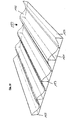
- FIG. 2 shows in a perspective view of another embodiment of a panel 20, which substantially the outer shape of the first embodiment according to FIG. 1 having.
- the panels 20 also consist of a lower outer shell 21 and an upper structured shell 22.
- the height of the webs 23, 24 is determined by the shape of the upper structured shell 22.
- Between the webs 23, 24 further inner shells 25, 26 are arranged.
- the inner shells 25, 26 are formed approximately parallel to the lower shell 21. However, there is a possibility that the inner shells 25, 26 approximately follow the shape of the upper structured shell 22.
- a spring 29 and a groove 30 are formed, which are provided for connection of the individual panels 20 with each other. Furthermore, a recess 31 or 32 is formed along the longitudinal edges, which after the joining of two adjacent panels 20 lead to a T-shaped recess which is provided for receiving a fastening element.
- the essential difference from the first exemplary embodiment is that, in addition to the outer shells 21, 22, further inner shells 25, 26 are provided.
- the number of inner shells 25, 26 can vary here and is determined by the desired thermal insulation. Thus, for example, only one inner panel 25, 26 could be formed, but it is also possible to provide a plurality of inner panels 25, 26.
- FIG. 3 shows in a perspective view of another embodiment of a panel 40, which in turn consists of a lower outer shell 41 and an upper outer shell 42.
- the outer shells 41, 42 are through Transverse webs 43, 44 connected to each other, wherein in addition inner shells 45, 46 are present.
- the outer shape and the inner shell structure largely corresponds to the embodiment according to FIG. 2 , Only the coupling elements along the longitudinal edges 47, 48 have a different design.
- a first longitudinal edge 47 is provided with a pin 49, while the opposite longitudinal edge 48 has a groove 50.
- the pin 49 is provided in cross section with a hook-shaped projection 51 which engages behind a projection 52 of the recess 50, so as to allow a connection between two adjacent panels 40.
- the fasteners are previously connected to the wall or roof construction.
- FIG. 4 shows in a perspective side view of another embodiment of a panel 60, which in turn consists of a lower outer shell 61 and an upper outer shell 62.
- the two outer shells 61, 62 are interconnected by transverse webs 63, 64.
- the height of the crossbars 63, 64 in turn depends on the distance of the outer shells 61, 62.
- the upper outer shell 62 is trapezoidal and thus has a lower parallel surface 65 relative to the lower shell 61 and a higher parallel surface 66. Beveled partial surfaces 67, 68 are arranged between the parallel surfaces 65, 66, so that a total of one integral outer shell 62 is formed, which is connected via the transverse webs 63, 64 with the lower outer shell 61.
- the longitudinal edges 69, 70 are as in the embodiment according to FIG. 1 equipped with a spring 71 and a groove 72 so that a plurality of adjacent panels 60 can be connected together.
- the attachment of the panels on an existing wall or roof surface is carried out with a suction anchor as a piece or a continuous suction anchor rung, which has a T-shaped projection, which in turn engages in the recess 73, 74.
- the recess 73, 74 have after joining two adjacent panels 60 a T-shaped cross-section, so that a sufficient grip is ensured by means of the mounting rail.
- FIG. 5 shows in a perspective view of another embodiment of a panel 80, which largely a shaping according to FIG. 4 having.
- These panels also have a lower outer shell 81 and an upper outer shell 82, which are connected to each other with transverse webs 83, 84.
- a spring 87 and a groove 88 and a recess 89, 90 is formed, wherein the groove 88 and spring 87 is provided for connection to adjacent panels 80, while the recess 89, 90 are provided for receiving a mounting rail .
- the panels 80 with additional inner shells 91, 92 equipped, similar to the embodiment of the FIG. 3 The number of shells depends on the height and the thermal boundary conditions, which should comply with the panels 80. Thus, if necessary, only an inner shell 91, 92 or possibly the use of a plurality of inner shells 91, 92 is possible.
- FIG. 6 shows in a perspective view of another embodiment of a panel 100.
- the panel 100 has a lower outer shell 101 and a trapezoidal upper outer shell 102 formed.
- this embodiment corresponds to the embodiment according to FIG. 5
- other coupling elements are formed on the longitudinal edges 103, 104.
- the coupling elements consist of a pin 105 and a corresponding groove 106, as for example from the FIG. 3 are provided in another embodiment.
- Via a hook-shaped projection 107 which engages behind a projection 108 of the groove 106, a locking of adjacent panels 100 takes place, again having the advantage that this type of panels 100 is pressed from above into the adjacent panels 100 and removed in the same way can be.
- the lower outer shell 101 is in turn connected to the profiled outer shell 102 via transverse webs 109, 110, wherein the entire panel 100 is manufactured in one piece by an extrusion process.
- FIG. 7 shows in a perspective view of another embodiment of a panel 120.
- the panel 120 has a lower shell 121 and a sinusoidally shaped upper outer shell 122 on.
- the outer shells 121, 122 are connected to each other by transverse webs 123, wherein optionally in a further embodiment, additional inner shells may be formed.
- the upper outer shell 121 is formed overlapping on both longitudinal edges 124, 125.
- the overlap 126 serves to be applied to the adjacent panels or roofing so as to ensure a secure closure and, for example, to prevent the ingress of moisture.
- the longitudinal edges 124, 125 are in this case limited in particular by a transverse strut 123 formed on the edge side.
- FIG. 8 shows in a perspective view of another embodiment of a panel 130, which also consists of a lower outer shell 131 and an upper outer shell 132. While the outer shell 131 is planar, the upper outer shell 132 is trapezoidal in shape. The two outer shells 131, 132 are in turn connected to each other by transverse webs 133. At the longitudinal edges 134, 135 an overlap 136 is again formed, which is provided for resting on the adjacent panels. The longitudinal edges 134, 135 are formed by the outer transverse webs 133.
- FIG. 9 shows in a perspective view of another embodiment of a panel 140, which consists of a lower outer shell 141 and an upper outer shell 142.
- the two outer shells 141, 142 are interconnected by transverse webs 143.
- the upper outer shell 142 is in turn trapezoidal, but this faces the FIG. 8 at the longitudinal edges 144, 145 no overlap.
- FIG. 10 shows in a perspective view of another embodiment according to FIG. 7 but without overlap.
- the panel 150 is in turn formed by a flat outer shell 151 and a sinusoidally shaped upper outer shell 152 in this case, which are interconnected by transverse webs 153. At the longitudinal edges 154, 155 no overlap is formed.
- FIG. 11 shows in a plan view a particular embodiment of a panel 160, which consists of a lower outer shell 161 and an upper sinusoidally shaped outer shell 162.
- a coupling element 165 is formed, which largely corresponds to the previously described embodiments.
- a groove 166 is formed, which has a T-shaped cross-section after joining two adjacent panels 160 and for attachment to the existing roof construction.
- the peculiarity of the panels 160 is that over the previous embodiment, the inner shells do not follow the course of the two outer shells 161, 162, but have a rectangular subdivision, so that can be dispensed with in this special case on further transverse webs.
- the rectangular design is achieved by overlapping shells 164.
- FIG. 12 shows a further embodiment of a panel 170 in a plan view.
- the panel 170 consists of a flat outer shell 171 and a sinusoidally shaped upper outer shell 172. These panels 170 has coupling elements 175 and a groove 176, which in turn has a T-shaped cross-section after the joining of two adjacent panels and for fastening the Panel 170 is used.
- the peculiarity of these panels 170 is that the inner structure is honeycomb-shaped, so that can also be dispensed with transverse webs.
- the individual honeycombs 174 are formed by shells 177, which give an approximately honeycomb hexagonal structure.
- the fastening element 204 engages with a T-shaped projection 206 in the existing recess 31, 32 of the panels 20, so that in the case of Tensile forces or wind load the panels 20 are held securely in the central region.
- the lateral roofing 203 consists of sandwich panels, which on the outside either has a plastic or aluminum coating and is filled in the middle area with a polyurethane foam.
- the polyurethane foam is used in the roofing 203, while the panels 20 by a plurality of hollow chambers, which arise through the inner shells 25, 26 and transverse webs 23, 24, also allow good thermal insulation.
- the particular advantage of this embodiment of the panels 20 is that compared to the other roofing 203 normal daylight can get into the spaces below.
- the panels 20 is in a transparent design or at least semi-translucent.
- FIG. 14 shows in a perspective view the arrangement of the panels 20 on the roof structure 200 with rafters 201 after installation. It can be seen again that two panels 20 are used as a replacement for an existing roofing 203, wherein the roofing 203 and the panels 20 are held by a fastening profile 202. The panels 20 are additionally held by a fastening element 204 in the region of the coupling elements 29, 30 in order to ensure sufficient hold of the panels 20 even under extreme wind loads.
- the structure of the panels 20 corresponds to the described shape according to FIG. 13 and can, as already stated, however, be replaced by another structure according to the invention.
- the illustrated embodiment for mounting the panels 20 follows in the present case for a roofing 203 but can readily be transferred in a similar form to a wall covering, in which case a loss is required to the individual wall elements and panels 20 used by means of fastening profiles safely anchored.
- the structure of the panels 20 can be adapted to an existing wall cladding in such a way that no difference is found with the exception of a possible color design.
- All variants of the panels 1, 20, 40, 60, 80, 100, 120, 130, 140, 150, 160, 170 is based on a nearly identical production process, in which after the extrusion process by plastic deformation on at least one panel side, a structure of an outer Shell is generated.
Landscapes
- Engineering & Computer Science (AREA)
- Architecture (AREA)
- Civil Engineering (AREA)
- Structural Engineering (AREA)
- Roof Covering Using Slabs Or Stiff Sheets (AREA)
- Finishing Walls (AREA)
Applications Claiming Priority (2)
| Application Number | Priority Date | Filing Date | Title |
|---|---|---|---|
| DE202010014593 | 2010-10-25 | ||
| DE202011003120U DE202011003120U1 (de) | 2010-10-25 | 2011-02-23 | Bauelement |
Publications (2)
| Publication Number | Publication Date |
|---|---|
| EP2444568A2 true EP2444568A2 (fr) | 2012-04-25 |
| EP2444568A3 EP2444568A3 (fr) | 2014-07-02 |
Family
ID=44508165
Family Applications (1)
| Application Number | Title | Priority Date | Filing Date |
|---|---|---|---|
| EP11008540.4A Withdrawn EP2444568A3 (fr) | 2010-10-25 | 2011-10-25 | Elément de construction |
Country Status (2)
| Country | Link |
|---|---|
| EP (1) | EP2444568A3 (fr) |
| DE (1) | DE202011003120U1 (fr) |
Cited By (3)
| Publication number | Priority date | Publication date | Assignee | Title |
|---|---|---|---|---|
| RU2728440C1 (ru) * | 2019-10-21 | 2020-07-29 | Общество с ограниченной ответственностью "СафПласт" | Способ получения и конструкция замковых многослойных панелей из поликарбоната |
| CN111945992A (zh) * | 2020-07-28 | 2020-11-17 | 湖南恒信新型建材有限公司 | 一种装配式竹木纤维板的安装方法 |
| EP4290032A1 (fr) * | 2022-06-06 | 2023-12-13 | Adopen Plastik Ve Insaat Sanayi Anonim Sirketi | Panneau et système de revêtement |
Families Citing this family (5)
| Publication number | Priority date | Publication date | Assignee | Title |
|---|---|---|---|---|
| DE102012111019A1 (de) * | 2012-11-15 | 2014-05-15 | Guido Schulte | Paneelsystem für die Montage an Wänden, Decken oder Böden |
| GB202202834D0 (en) | 2022-03-01 | 2022-04-13 | Bauglasindustrie Gmbh | Glazing |
| GB202211191D0 (en) | 2022-08-01 | 2022-09-14 | Bauglasindustrie Gmbh | Glazing |
| GB202211196D0 (en) | 2022-08-01 | 2022-09-14 | Bauglasindustrie Gmbh | Glazing |
| GB202313335D0 (en) | 2023-09-01 | 2023-10-18 | Bauglasindustrie Gmbh | Glazing |
Family Cites Families (8)
| Publication number | Priority date | Publication date | Assignee | Title |
|---|---|---|---|---|
| DE4000955C2 (de) * | 1990-01-16 | 2002-01-10 | Aluform System Technik Pohl Gm | Lichtelement für geschäumte Polyurethan-Dachelemente |
| GB2269833A (en) * | 1992-08-21 | 1994-02-23 | Eurolyte Limited | Roof or wall panel |
| FR2715181B1 (fr) * | 1994-01-20 | 1996-03-08 | Fornells Sa | Elément de bardage pour la construction de palissades modulaires. |
| GB9904994D0 (en) * | 1999-03-05 | 1999-04-28 | Snow Raymond G | Improvements in roof panels |
| EP1316407B1 (fr) * | 2001-11-30 | 2006-03-01 | Rodeca GmbH | Panneau pour des murs et des toits et procedé et dispositif de production |
| NL1026939C2 (nl) * | 2004-08-31 | 2006-03-01 | Jelle Horeman | Lichtdoorlatend paneel en werkwijze voor de vervaardiging daarvan. |
| CN101175399A (zh) * | 2005-05-13 | 2008-05-07 | 陶氏环球技术公司 | 温室板 |
| FR2912157A1 (fr) * | 2007-02-06 | 2008-08-08 | Cyrille Coadou | Ligne de fabrication de plaque de sol synthetique |
-
2011
- 2011-02-23 DE DE202011003120U patent/DE202011003120U1/de not_active Expired - Lifetime
- 2011-10-25 EP EP11008540.4A patent/EP2444568A3/fr not_active Withdrawn
Non-Patent Citations (1)
| Title |
|---|
| None |
Cited By (3)
| Publication number | Priority date | Publication date | Assignee | Title |
|---|---|---|---|---|
| RU2728440C1 (ru) * | 2019-10-21 | 2020-07-29 | Общество с ограниченной ответственностью "СафПласт" | Способ получения и конструкция замковых многослойных панелей из поликарбоната |
| CN111945992A (zh) * | 2020-07-28 | 2020-11-17 | 湖南恒信新型建材有限公司 | 一种装配式竹木纤维板的安装方法 |
| EP4290032A1 (fr) * | 2022-06-06 | 2023-12-13 | Adopen Plastik Ve Insaat Sanayi Anonim Sirketi | Panneau et système de revêtement |
Also Published As
| Publication number | Publication date |
|---|---|
| EP2444568A3 (fr) | 2014-07-02 |
| DE202011003120U1 (de) | 2011-07-27 |
Similar Documents
| Publication | Publication Date | Title |
|---|---|---|
| EP2444568A2 (fr) | Elément de construction | |
| DE69528547T2 (de) | System beinhaltend vorgefertigte Platten für Bauten und Konstruktion | |
| EP0585663A1 (fr) | Elément de revêtement pour sols, plafonds et murs | |
| DE60031129T2 (de) | Deckensystem mit austauschbaren platten | |
| EP1524385B1 (fr) | Panneau extrudé, en particulier pour revêtement de sol | |
| DE29825035U1 (de) | Wandkassette | |
| DE2018497A1 (de) | System aus vereinigten Platten zur Bildung von Oberlichtern | |
| EP0194435A2 (fr) | Dispositif pour la réalisation de joints d'expansion dans des surfaces de plancher ou de béton | |
| DE60019338T2 (de) | Bauelemente | |
| WO2002044497A1 (fr) | Procede pour fixer des plaques d'isolation thermique et douille necessaire a cet effet | |
| DE29924180U1 (de) | Trägerplatte aus folienartigem Kunststoff für einen plattenbekleideten Bodenaufbau oder eine Wand | |
| EP2527763B1 (fr) | Système d'habillage destiné à l'habillage d'une surface extérieure d'un bâtiment | |
| DE69709294T2 (de) | Vorrichtung zum erneuten Profilieren von Wellpappen | |
| CH628385A5 (en) | Heat-insulating inner cladding on a roof borne by rafters | |
| EP1290307B1 (fr) | Element de construction, utilisation d'un element de construction et procede de fabrication d'un element de construction | |
| DE69421428T2 (de) | Paneel für die Bauindustrie | |
| DE3114732A1 (de) | "putzfassade mit waerme-kaelte-daemmplatten" | |
| DE2325281A1 (de) | Metalltraegerelement fuer bauwerksdecken und aus diesem metalltraegerelement und einer betonschicht gebildeten bauwerksdecke | |
| WO2013026822A1 (fr) | Élément translucide de toit ou de paroi, en tôle | |
| EP1249556A2 (fr) | Feuille de tôle profilée | |
| WO1997004197A1 (fr) | Assortiment d'equerres en matiere plastique pour l'industrie du batiment | |
| DE202012006046U1 (de) | Wärmedämmplatte für Gebäudefassaden | |
| AT10488U1 (de) | Putzleiste aus kunststoff zum erzeugen von putzschicht - ecken | |
| DE102011008321B4 (de) | Anschlussfugendichtung | |
| EP1989369B1 (fr) | Plaque structurelle |
Legal Events
| Date | Code | Title | Description |
|---|---|---|---|
| AK | Designated contracting states |
Kind code of ref document: A2 Designated state(s): AL AT BE BG CH CY CZ DE DK EE ES FI FR GB GR HR HU IE IS IT LI LT LU LV MC MK MT NL NO PL PT RO RS SE SI SK SM TR |
|
| AX | Request for extension of the european patent |
Extension state: BA ME |
|
| PUAI | Public reference made under article 153(3) epc to a published international application that has entered the european phase |
Free format text: ORIGINAL CODE: 0009012 |
|
| PUAL | Search report despatched |
Free format text: ORIGINAL CODE: 0009013 |
|
| AK | Designated contracting states |
Kind code of ref document: A3 Designated state(s): AL AT BE BG CH CY CZ DE DK EE ES FI FR GB GR HR HU IE IS IT LI LT LU LV MC MK MT NL NO PL PT RO RS SE SI SK SM TR |
|
| AX | Request for extension of the european patent |
Extension state: BA ME |
|
| RIC1 | Information provided on ipc code assigned before grant |
Ipc: E04D 3/28 20060101AFI20140526BHEP Ipc: E04F 13/18 20060101ALI20140526BHEP Ipc: B29C 47/14 20060101ALI20140526BHEP Ipc: E04C 2/54 20060101ALI20140526BHEP |
|
| STAA | Information on the status of an ep patent application or granted ep patent |
Free format text: STATUS: THE APPLICATION IS DEEMED TO BE WITHDRAWN |
|
| 18D | Application deemed to be withdrawn |
Effective date: 20150106 |