EP2444652A2 - Soupape de réglage à haute pression - Google Patents
Soupape de réglage à haute pression Download PDFInfo
- Publication number
- EP2444652A2 EP2444652A2 EP11186025A EP11186025A EP2444652A2 EP 2444652 A2 EP2444652 A2 EP 2444652A2 EP 11186025 A EP11186025 A EP 11186025A EP 11186025 A EP11186025 A EP 11186025A EP 2444652 A2 EP2444652 A2 EP 2444652A2
- Authority
- EP
- European Patent Office
- Prior art keywords
- valve
- extension
- pressure control
- outlet
- control valve
- Prior art date
- Legal status (The legal status is an assumption and is not a legal conclusion. Google has not performed a legal analysis and makes no representation as to the accuracy of the status listed.)
- Withdrawn
Links
- 230000001105 regulatory effect Effects 0.000 title 1
- 238000007789 sealing Methods 0.000 claims abstract description 29
- 230000002093 peripheral effect Effects 0.000 claims description 2
- 239000000463 material Substances 0.000 description 10
- 230000003628 erosive effect Effects 0.000 description 7
- 230000006835 compression Effects 0.000 description 5
- 238000007906 compression Methods 0.000 description 5
- 239000012530 fluid Substances 0.000 description 5
- 230000001419 dependent effect Effects 0.000 description 3
- 239000000446 fuel Substances 0.000 description 3
- 239000007788 liquid Substances 0.000 description 3
- 239000002245 particle Substances 0.000 description 2
- 230000003313 weakening effect Effects 0.000 description 2
- 238000003466 welding Methods 0.000 description 2
- 229910000760 Hardened steel Inorganic materials 0.000 description 1
- 238000011161 development Methods 0.000 description 1
- 230000018109 developmental process Effects 0.000 description 1
- 230000001747 exhibiting effect Effects 0.000 description 1
- 230000002349 favourable effect Effects 0.000 description 1
- 238000009434 installation Methods 0.000 description 1
- 238000000034 method Methods 0.000 description 1
- 230000035515 penetration Effects 0.000 description 1
Images

Classifications
-
- F—MECHANICAL ENGINEERING; LIGHTING; HEATING; WEAPONS; BLASTING
- F02—COMBUSTION ENGINES; HOT-GAS OR COMBUSTION-PRODUCT ENGINE PLANTS
- F02M—SUPPLYING COMBUSTION ENGINES IN GENERAL WITH COMBUSTIBLE MIXTURES OR CONSTITUENTS THEREOF
- F02M63/00—Other fuel-injection apparatus having pertinent characteristics not provided for in groups F02M39/00 - F02M57/00 or F02M67/00; Details, component parts, or accessories of fuel-injection apparatus, not provided for in, or of interest apart from, the apparatus of groups F02M39/00 - F02M61/00 or F02M67/00; Combination of fuel pump with other devices, e.g. lubricating oil pump
- F02M63/0012—Valves
- F02M63/0014—Valves characterised by the valve actuating means
- F02M63/0015—Valves characterised by the valve actuating means electrical, e.g. using solenoid
- F02M63/0017—Valves characterised by the valve actuating means electrical, e.g. using solenoid using electromagnetic operating means
- F02M63/0021—Valves characterised by the valve actuating means electrical, e.g. using solenoid using electromagnetic operating means characterised by the arrangement of mobile armatures
-
- F—MECHANICAL ENGINEERING; LIGHTING; HEATING; WEAPONS; BLASTING
- F02—COMBUSTION ENGINES; HOT-GAS OR COMBUSTION-PRODUCT ENGINE PLANTS
- F02M—SUPPLYING COMBUSTION ENGINES IN GENERAL WITH COMBUSTIBLE MIXTURES OR CONSTITUENTS THEREOF
- F02M63/00—Other fuel-injection apparatus having pertinent characteristics not provided for in groups F02M39/00 - F02M57/00 or F02M67/00; Details, component parts, or accessories of fuel-injection apparatus, not provided for in, or of interest apart from, the apparatus of groups F02M39/00 - F02M61/00 or F02M67/00; Combination of fuel pump with other devices, e.g. lubricating oil pump
- F02M63/0012—Valves
- F02M63/0031—Valves characterized by the type of valves, e.g. special valve member details, valve seat details, valve housing details
- F02M63/0033—Lift valves, i.e. having a valve member that moves perpendicularly to the plane of the valve seat
- F02M63/0036—Lift valves, i.e. having a valve member that moves perpendicularly to the plane of the valve seat with spherical or partly spherical shaped valve member ends
-
- F—MECHANICAL ENGINEERING; LIGHTING; HEATING; WEAPONS; BLASTING
- F02—COMBUSTION ENGINES; HOT-GAS OR COMBUSTION-PRODUCT ENGINE PLANTS
- F02M—SUPPLYING COMBUSTION ENGINES IN GENERAL WITH COMBUSTIBLE MIXTURES OR CONSTITUENTS THEREOF
- F02M63/00—Other fuel-injection apparatus having pertinent characteristics not provided for in groups F02M39/00 - F02M57/00 or F02M67/00; Details, component parts, or accessories of fuel-injection apparatus, not provided for in, or of interest apart from, the apparatus of groups F02M39/00 - F02M61/00 or F02M67/00; Combination of fuel pump with other devices, e.g. lubricating oil pump
- F02M63/0012—Valves
- F02M63/0031—Valves characterized by the type of valves, e.g. special valve member details, valve seat details, valve housing details
- F02M63/005—Pressure relief valves
- F02M63/0052—Pressure relief valves with means for adjusting the opening pressure, e.g. electrically controlled
-
- F—MECHANICAL ENGINEERING; LIGHTING; HEATING; WEAPONS; BLASTING
- F02—COMBUSTION ENGINES; HOT-GAS OR COMBUSTION-PRODUCT ENGINE PLANTS
- F02M—SUPPLYING COMBUSTION ENGINES IN GENERAL WITH COMBUSTIBLE MIXTURES OR CONSTITUENTS THEREOF
- F02M63/00—Other fuel-injection apparatus having pertinent characteristics not provided for in groups F02M39/00 - F02M57/00 or F02M67/00; Details, component parts, or accessories of fuel-injection apparatus, not provided for in, or of interest apart from, the apparatus of groups F02M39/00 - F02M61/00 or F02M67/00; Combination of fuel pump with other devices, e.g. lubricating oil pump
- F02M63/0012—Valves
- F02M63/007—Details not provided for in, or of interest apart from, the apparatus of the groups F02M63/0014 - F02M63/0059
- F02M63/0071—Details not provided for in, or of interest apart from, the apparatus of the groups F02M63/0014 - F02M63/0059 characterised by guiding or centering means in valves including the absence of any guiding means, e.g. "flying arrangements"
-
- F—MECHANICAL ENGINEERING; LIGHTING; HEATING; WEAPONS; BLASTING
- F02—COMBUSTION ENGINES; HOT-GAS OR COMBUSTION-PRODUCT ENGINE PLANTS
- F02M—SUPPLYING COMBUSTION ENGINES IN GENERAL WITH COMBUSTIBLE MIXTURES OR CONSTITUENTS THEREOF
- F02M63/00—Other fuel-injection apparatus having pertinent characteristics not provided for in groups F02M39/00 - F02M57/00 or F02M67/00; Details, component parts, or accessories of fuel-injection apparatus, not provided for in, or of interest apart from, the apparatus of groups F02M39/00 - F02M61/00 or F02M67/00; Combination of fuel pump with other devices, e.g. lubricating oil pump
- F02M63/0012—Valves
- F02M63/007—Details not provided for in, or of interest apart from, the apparatus of the groups F02M63/0014 - F02M63/0059
- F02M63/0077—Valve seat details
-
- F—MECHANICAL ENGINEERING; LIGHTING; HEATING; WEAPONS; BLASTING
- F02—COMBUSTION ENGINES; HOT-GAS OR COMBUSTION-PRODUCT ENGINE PLANTS
- F02M—SUPPLYING COMBUSTION ENGINES IN GENERAL WITH COMBUSTIBLE MIXTURES OR CONSTITUENTS THEREOF
- F02M63/00—Other fuel-injection apparatus having pertinent characteristics not provided for in groups F02M39/00 - F02M57/00 or F02M67/00; Details, component parts, or accessories of fuel-injection apparatus, not provided for in, or of interest apart from, the apparatus of groups F02M39/00 - F02M61/00 or F02M67/00; Combination of fuel pump with other devices, e.g. lubricating oil pump
- F02M63/02—Fuel-injection apparatus having several injectors fed by a common pumping element, or having several pumping elements feeding a common injector; Fuel-injection apparatus having provisions for cutting-out pumps, pumping elements, or injectors; Fuel-injection apparatus having provisions for variably interconnecting pumping elements and injectors alternatively
- F02M63/0225—Fuel-injection apparatus having a common rail feeding several injectors ; Means for varying pressure in common rails; Pumps feeding common rails
- F02M63/023—Means for varying pressure in common rails
- F02M63/0235—Means for varying pressure in common rails by bleeding fuel pressure
- F02M63/025—Means for varying pressure in common rails by bleeding fuel pressure from the common rail
-
- F—MECHANICAL ENGINEERING; LIGHTING; HEATING; WEAPONS; BLASTING
- F16—ENGINEERING ELEMENTS AND UNITS; GENERAL MEASURES FOR PRODUCING AND MAINTAINING EFFECTIVE FUNCTIONING OF MACHINES OR INSTALLATIONS; THERMAL INSULATION IN GENERAL
- F16K—VALVES; TAPS; COCKS; ACTUATING-FLOATS; DEVICES FOR VENTING OR AERATING
- F16K31/00—Actuating devices; Operating means; Releasing devices
- F16K31/02—Actuating devices; Operating means; Releasing devices electric; magnetic
- F16K31/06—Actuating devices; Operating means; Releasing devices electric; magnetic using a magnet, e.g. diaphragm valves, cutting off by means of a liquid
- F16K31/0644—One-way valve
- F16K31/0655—Lift valves
- F16K31/0665—Lift valves with valve member being at least partially ball-shaped
-
- F—MECHANICAL ENGINEERING; LIGHTING; HEATING; WEAPONS; BLASTING
- F02—COMBUSTION ENGINES; HOT-GAS OR COMBUSTION-PRODUCT ENGINE PLANTS
- F02M—SUPPLYING COMBUSTION ENGINES IN GENERAL WITH COMBUSTIBLE MIXTURES OR CONSTITUENTS THEREOF
- F02M2200/00—Details of fuel-injection apparatus, not otherwise provided for
- F02M2200/02—Fuel-injection apparatus having means for reducing wear
-
- F—MECHANICAL ENGINEERING; LIGHTING; HEATING; WEAPONS; BLASTING
- F02—COMBUSTION ENGINES; HOT-GAS OR COMBUSTION-PRODUCT ENGINE PLANTS
- F02M—SUPPLYING COMBUSTION ENGINES IN GENERAL WITH COMBUSTIBLE MIXTURES OR CONSTITUENTS THEREOF
- F02M2200/00—Details of fuel-injection apparatus, not otherwise provided for
- F02M2200/04—Fuel-injection apparatus having means for avoiding effect of cavitation, e.g. erosion
Definitions
- the present invention relates to a high-pressure control valve according to the preamble of patent claim 1.
- Such high-pressure control valves are known from the prior art, for example, for pressure control in common rail engines.
- the high pressure control of liquids is generally done via ball seat valves. These are usually controlled electromagnetically. Electromagnetically operated high-pressure control valves of the prior art are generally constructed as follows, an example being in FIG. 3 shown.
- the valve 1 has a valve body 2 with an inlet 20 and an outlet 21, with pressures on the inlet side, for example in the field of application of the common rail engines, currently being up to 2400 bar. Between the inlet 20 and the outlet 21, a valve seat 3 is arranged, through which a valve bore 30, the inlet 20 and outlet 21 connects, is guided.
- the valve bore 30 is on the outlet side by a sealing means 4, which is usually designed as a sealing ball, sealable.
- the sealing ball 4 can be pressed via a valve pin 5 against the valve seat 3.
- the valve seat 3 is made of hardened steel due to the increased loads acting through the sealing ball 4. For cost reasons, the remaining valve body 2 is made of uncured material.
- the valve seat 3 is disposed on the valve body 2 so as to connect the inlet side and the outlet side.
- the valve seat 3 is designed on the outlet side substantially plate-shaped and has in the region of the valve bore 30 has a recess in which the sealing ball 4 comes to rest. He is the inlet side pressed into the valve body 2.
- the outlet 21 is formed by radial bores 23 on the outlet side of the valve body 2.
- the radial bores are arranged as close as possible below the valve seat 3.
- a shoulder 22 is formed between the valve seat 3 and the outlet bores 23, on which the valve seat 3 is supported during the screwing of the valve.
- the valve pin 5 is mounted in a longitudinal bore of the valve body 2 and movable via an outlet side arranged electromagnetic drive unit 6 along its longitudinal axis.
- the drive unit 6 is not shown here. As a rule, it is constructed from an energizable coil 61 arranged on a coil carrier 60 and an armature 62 which can be actuated by a generated magnetic field.
- the armature 62 and the valve pin 5 are welded or pressed together and fixedly connected.
- the armature 62 is also biased in the closing direction of the valve by means of a compression spring 68, so that the valve is closed in the de-energized state of the coil 61.
- the armature 62 and the compression spring 68 are at the back in a bushing 65, which is attached to the valve body, for example. Via a welding ring 66, stored. The valve pin 5 is held centered in the sleeve 65 via a bearing 69.
- the control of the fluid flow takes place by lifting the sealing ball 4 of the valve seat 3.
- current high-pressure control valves 1 is the maximum stroke, ie the stroke that is reached at maximum opening of the valve, 0.2 - 0.5 mm.
- very high flow velocities of the controlled fluid are achieved due to the pressure acting on the sealing ball 4 from the inlet side.
- the liquid then bounces at this high flow rate on the outlet-side shoulder 22 of the valve body 2 and erodes it, that is worn in the course of the life of the valve increasingly more material of the paragraph 22, so that it is weakened in its material thickness.
- a weakening of the valve body 2 in this area means serious disadvantages in terms of the life of the valve, since with increasing erosion less forces from the screw can be transmitted via the valve seat 3 to the valve body 2, so that the valve is finally leaking in the region of the pressure.
- a high-pressure control valve has a valve body with an inlet and an outlet, wherein the outlet is formed by at least one substantially radially extending opening in the valve body.
- a substantially disk-shaped valve seat is disposed on the valve body between the inlet and outlet and has a valve bore which connects the inlet and the outlet with each other.
- a sealing element which is arranged on an actuating element suitable for sealingly closing the valve bore.
- the actuating element is also movable via an actuating device such that opening and closing of the valve can be effected.
- the valve seat is designed in such a way that the outlet side has a peripheral extension extending axially from the base of the valve seat in the direction of the opening.
- An aerodynamically particularly favorable embodiment of the extension is achieved when this is designed as a funnel-shaped collar exhibiting. In this way flow turbulences can be reduced. Depending on the angle at which the funnel-shaped collar expands, can In addition, a stroke-dependent characteristic of the flow cross-section are designed.
- extension covers at least half of the extension between the base and the opening, a significant reduction of the erosion of the valve body in the region of the outlet opening can already be achieved.
- extension covers at least 9/10 of the extension between the base surface and the opening, wherein ideally the complete extension between the base surface and the opening is covered by the extension.
- the extension can furthermore be configured in such a way that direct opening of the valve body is completely avoided when the valve is opened.
- the extension may also have a recess adapted to the sealing element, so that an optimized contact surface for Seal between the valve seat and the sealing element is formed.
- the sealing element is preferably designed as a sealing ball. This has the advantage that due to the rotationally symmetrical design of a ball, a particularly good seal with respect to a bore can take place.
- An actuation of the sealing element can be made particularly simple if the actuating element is designed as an actuating pin.
- a pin-shaped configuration of the actuating element has the advantage that it can be guided in this way particularly easily by the valve body in the direction of the actuating device, which is designed for example as an electromagnet.
- a flow cross-section between the actuating element and the extension is designed such that turbulence in the flow can be reduced. In this way, a particularly regular fluid flow is achieved and it is reduced by turbulence in the fluid circuit induced forces.
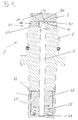
- FIG. 1 shows a cross section of a high-pressure control valve 1 according to the invention.
- the high-pressure control valve 1 has a substantially cylindrical valve body 2, which has an axially extending inlet 20 and a radially extending outlet 21.
- the outlet 21 is presently formed by radially guided bores 23.
- a disc-shaped valve seat 3 is arranged on the valve body 2, which connects the inlet 20 and the outlet 21 via a valve bore 30.
- the valve seat 3 is held on the valve body 2 via a pressure and is braced during installation of the valve 1 in the direction of the valve body 2.
- valve bore 30 can be closed by a sealing element 4 designed as a sealing ball.
- the sealing ball 4 can be pressed against the valve seat 3 for closing the valve bore 30 via an actuating element 5 which is shaped as an actuating pin and which is mounted in an axially extending bore of the valve body 2.
- the valve pin 5 is axially displaceable via an actuating arrangement 6, which is designed in the present case as an electromagnet.
- the electromagnet 6 is essentially constructed from a coil 61 arranged circumferentially to the valve body 2 and on a coil support 60, as well as an armature 62 axially displaceably mounted inside the coil 61 and connected to the valve body 2 via a housing 63.
- a movement of the armature 62 in the axial direction is transmitted via the valve pin 5 to the sealing ball 4, so that opening and closing of the high-pressure control valve 1 is made possible.
- the armature 62 is additionally mounted in a sleeve 65 and biased in the direction of the valve pin 5 by means of a compression spring 68.
- the high pressure control valve 1 is in the de-energized state of the coil 61 to a pressure which is determined by the spring force of the compression spring 68, closed. For pressures beyond this, additional energization of the coil 61 is necessary in order to keep the high-pressure control valve 1 closed against a pressure present at the inlet 20.
- An energization of the coil 61 can take place via laterally outwardly guided connection contacts 64.
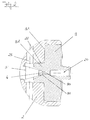
- FIG. 2 shows an enlargement of the valve seat of the high-pressure control valve FIG. 1 ,
- valve seat 3 is extended starting from a base surface 31 of the valve seat in the direction of the radially extending bore 23 of the outlet 21.
- This extension 32 is formed as a circumferential collar-shaped extension 32 which widens in a funnel shape starting from the valve bore 30.
- the extension 32 is guided approximately up to the radially extending bore 23, so that approximately 9/10 of the shoulder 22 formed between the radially extending bore 23 and the base of the valve seat 31 are covered by the extension 32. In this way, it is achieved that a liquid which is present at high pressure on the inlet side and flows past the sealing ball 4 when the valve is opened at a very high flow velocity is not directed directly onto the shoulder 22. In this way, erosion of the valve body 2 in this area is avoided.
- the sealing ball 4 can be pressed via the valve pin 5 against a receptacle 36, which is arranged at the outlet end of the valve bore 30.
- a receptacle 36 which is arranged at the outlet end of the valve bore 30.
Landscapes
- Engineering & Computer Science (AREA)
- General Engineering & Computer Science (AREA)
- Mechanical Engineering (AREA)
- Chemical & Material Sciences (AREA)
- Combustion & Propulsion (AREA)
- Physics & Mathematics (AREA)
- Electromagnetism (AREA)
- Control Of Fluid Pressure (AREA)
- Magnetically Actuated Valves (AREA)
Priority Applications (1)
| Application Number | Priority Date | Filing Date | Title |
|---|---|---|---|
| EP11186025.0A EP2444652A3 (fr) | 2010-10-21 | 2011-10-20 | Soupape de réglage à haute pression |
Applications Claiming Priority (2)
| Application Number | Priority Date | Filing Date | Title |
|---|---|---|---|
| DE102010049035A DE102010049035A1 (de) | 2010-10-21 | 2010-10-21 | Hochdruckregelventil |
| EP11186025.0A EP2444652A3 (fr) | 2010-10-21 | 2011-10-20 | Soupape de réglage à haute pression |
Publications (2)
| Publication Number | Publication Date |
|---|---|
| EP2444652A2 true EP2444652A2 (fr) | 2012-04-25 |
| EP2444652A3 EP2444652A3 (fr) | 2013-07-24 |
Family
ID=48579640
Family Applications (1)
| Application Number | Title | Priority Date | Filing Date |
|---|---|---|---|
| EP11186025.0A Withdrawn EP2444652A3 (fr) | 2010-10-21 | 2011-10-20 | Soupape de réglage à haute pression |
Country Status (1)
| Country | Link |
|---|---|
| EP (1) | EP2444652A3 (fr) |
Cited By (4)
| Publication number | Priority date | Publication date | Assignee | Title |
|---|---|---|---|---|
| WO2013172764A1 (fr) * | 2012-05-16 | 2013-11-21 | Scania Cv Ab | Soupape pour système de carburant pour moteur à combustion et procédé de commande d'un système de carburant pour moteur à combustion |
| WO2014095595A1 (fr) * | 2012-12-18 | 2014-06-26 | Delphi International Operations Luxembourg S.À.R.L. | Buse, vanne haute pression apte a recevoir la buse et rampe commune apte a recevoir la buse |
| WO2015055512A1 (fr) * | 2013-10-15 | 2015-04-23 | Continental Automotive Gmbh | Soupape |
| EP2905669A3 (fr) * | 2014-02-11 | 2015-12-30 | Kendrion (Villingen) GmbH | Vanne de régulation de pression |
Family Cites Families (4)
| Publication number | Priority date | Publication date | Assignee | Title |
|---|---|---|---|---|
| DE19700980A1 (de) * | 1997-01-14 | 1998-07-16 | Teves Gmbh Alfred | Elektromagnetventil |
| US7441546B2 (en) * | 2005-07-28 | 2008-10-28 | Denso Corporation | Valve apparatus |
| JP4193823B2 (ja) * | 2005-07-29 | 2008-12-10 | 株式会社デンソー | バルブ装置 |
| JP2009103050A (ja) * | 2007-10-23 | 2009-05-14 | Denso Corp | 電磁駆動装置 |
-
2011
- 2011-10-20 EP EP11186025.0A patent/EP2444652A3/fr not_active Withdrawn
Non-Patent Citations (1)
| Title |
|---|
| None |
Cited By (15)
| Publication number | Priority date | Publication date | Assignee | Title |
|---|---|---|---|---|
| EP2850311A4 (fr) * | 2012-05-16 | 2016-01-13 | Scania Cv Ab | Soupape pour système de carburant pour moteur à combustion et procédé de commande d'un système de carburant pour moteur à combustion |
| US9964089B2 (en) | 2012-05-16 | 2018-05-08 | Scania Cv Ab | Valve for a fuel system for a combustion engine and method for controlling a fuel system for a combustion engine |
| CN104285057A (zh) * | 2012-05-16 | 2015-01-14 | 斯堪尼亚商用车有限公司 | 用于燃烧发动机的燃料系统的阀和控制燃烧发动机的燃料系统的方法 |
| KR20150006885A (ko) * | 2012-05-16 | 2015-01-19 | 스카니아 씨브이 악티에볼라그 | 연소 엔진용 연료 시스템을 위한 밸브 및 연소 엔진용 연료 시스템을 제어하기 위한 방법 |
| CN104285057B (zh) * | 2012-05-16 | 2017-07-18 | 斯堪尼亚商用车有限公司 | 用于燃烧发动机的燃料系统的阀和控制燃烧发动机的燃料系统的方法 |
| WO2013172764A1 (fr) * | 2012-05-16 | 2013-11-21 | Scania Cv Ab | Soupape pour système de carburant pour moteur à combustion et procédé de commande d'un système de carburant pour moteur à combustion |
| KR101626535B1 (ko) | 2012-05-16 | 2016-06-13 | 스카니아 씨브이 악티에볼라그 | 연소 엔진용 연료 시스템을 위한 밸브 및 연소 엔진용 연료 시스템을 제어하기 위한 방법 |
| KR101709105B1 (ko) | 2012-12-18 | 2017-02-22 | 델피 인터내셔널 오퍼레이션즈 룩셈부르크 에스.에이 알.엘. | 노즐, 노즐을 수용할 수 있는 고압 밸브, 및 노즐을 수용할 수 있는 커먼 레일 |
| KR20150082630A (ko) * | 2012-12-18 | 2015-07-15 | 델피 인터내셔널 오퍼레이션즈 룩셈부르크 에스.에이 알.엘. | 노즐, 노즐을 수용할 수 있는 고압 밸브, 및 노즐을 수용할 수 있는 커먼 레일 |
| US9677524B2 (en) | 2012-12-18 | 2017-06-13 | Delphi International Operations Luxembourg S.A.R.L. | High pressure valve |
| WO2014095595A1 (fr) * | 2012-12-18 | 2014-06-26 | Delphi International Operations Luxembourg S.À.R.L. | Buse, vanne haute pression apte a recevoir la buse et rampe commune apte a recevoir la buse |
| EP3404250A1 (fr) * | 2012-12-18 | 2018-11-21 | Delphi International Operations Luxembourg S.à r.l. | Vanne haute pression |
| WO2015055512A1 (fr) * | 2013-10-15 | 2015-04-23 | Continental Automotive Gmbh | Soupape |
| US9803602B2 (en) | 2013-10-15 | 2017-10-31 | Continental Automotive Gmbh | Valve |
| EP2905669A3 (fr) * | 2014-02-11 | 2015-12-30 | Kendrion (Villingen) GmbH | Vanne de régulation de pression |
Also Published As
| Publication number | Publication date |
|---|---|
| EP2444652A3 (fr) | 2013-07-24 |
Similar Documents
| Publication | Publication Date | Title |
|---|---|---|
| EP2630360B1 (fr) | Vanne de réglage de haute pression | |
| EP2102486B1 (fr) | Injecteur avec une soupape de commande à compensation de pression axiale | |
| EP3161299B1 (fr) | Vanne à gaz | |
| EP3102863B1 (fr) | Soupape électromagnétique et système de refroidissement de moteur à combustion interne équipé d'une soupape électromagnétique | |
| DE102015005977A1 (de) | Entnahmeventil | |
| EP2444652A2 (fr) | Soupape de réglage à haute pression | |
| EP4150201B1 (fr) | Vanne de dosage de gaz pour moteur à combustion interne | |
| WO2011095367A1 (fr) | Ensemble soupape de commande d'un injecteur de carburant | |
| EP2757246A2 (fr) | Vanne haute pression | |
| EP2444653A2 (fr) | Soupape de réglage à haute pression | |
| EP2021616B1 (fr) | Électrovanne à espace d'induit noyé | |
| EP2314860B1 (fr) | Injecteur de carburant | |
| DE102015116240A1 (de) | Elektrischer Aktor einer Ventileinrichtung | |
| WO2016034402A1 (fr) | Soupape proportionnelle à commande électromagnétique | |
| WO2017080861A1 (fr) | Actionneur électromagnétique pour mécanisme de soupape | |
| EP2276922A1 (fr) | Injecteur de carburant avec electrovanne | |
| EP3420257B1 (fr) | Électrovanne | |
| WO2018028865A1 (fr) | Soupape d'aspiration à actionnement électromagnétique et pompe à carburant haute pression | |
| DE102006003484A1 (de) | Vorrichtung zum Einspritzen von Kraftstoff | |
| EP3032090B1 (fr) | Clapet de commutation ou de régulation de pression pour un système d'injection de carburant | |
| EP2596228B1 (fr) | Soupape de commande | |
| WO2019161878A1 (fr) | Dispositif de soupape pour système de fluide sous pression | |
| DE112018002148T5 (de) | Hochdruckkraftstoffversorgungspumpe | |
| EP3423717B1 (fr) | Soupape d'admission à commande électromagnétique et pompe haute pression munie d'une soupape d'admission | |
| WO2009080414A1 (fr) | Injecteur d'un système d'injection de carburant comprenant une soupape de commande à 3/2 voies |
Legal Events
| Date | Code | Title | Description |
|---|---|---|---|
| AK | Designated contracting states |
Kind code of ref document: A2 Designated state(s): AL AT BE BG CH CY CZ DE DK EE ES FI FR GB GR HR HU IE IS IT LI LT LU LV MC MK MT NL NO PL PT RO RS SE SI SK SM TR |
|
| AX | Request for extension of the european patent |
Extension state: BA ME |
|
| PUAI | Public reference made under article 153(3) epc to a published international application that has entered the european phase |
Free format text: ORIGINAL CODE: 0009012 |
|
| PUAL | Search report despatched |
Free format text: ORIGINAL CODE: 0009013 |
|
| AK | Designated contracting states |
Kind code of ref document: A3 Designated state(s): AL AT BE BG CH CY CZ DE DK EE ES FI FR GB GR HR HU IE IS IT LI LT LU LV MC MK MT NL NO PL PT RO RS SE SI SK SM TR |
|
| AX | Request for extension of the european patent |
Extension state: BA ME |
|
| RIC1 | Information provided on ipc code assigned before grant |
Ipc: F02M 63/00 20060101AFI20130620BHEP Ipc: F16K 31/06 20060101ALI20130620BHEP |
|
| STAA | Information on the status of an ep patent application or granted ep patent |
Free format text: STATUS: THE APPLICATION IS DEEMED TO BE WITHDRAWN |
|
| 18D | Application deemed to be withdrawn |
Effective date: 20140125 |