EP2444662A1 - Liaison de composants d'une éolienne - Google Patents
Liaison de composants d'une éolienne Download PDFInfo
- Publication number
- EP2444662A1 EP2444662A1 EP12151703A EP12151703A EP2444662A1 EP 2444662 A1 EP2444662 A1 EP 2444662A1 EP 12151703 A EP12151703 A EP 12151703A EP 12151703 A EP12151703 A EP 12151703A EP 2444662 A1 EP2444662 A1 EP 2444662A1
- Authority
- EP
- European Patent Office
- Prior art keywords
- component
- connection
- components
- contact surfaces
- intermediate connecting
- Prior art date
- Legal status (The legal status is an assumption and is not a legal conclusion. Google has not performed a legal analysis and makes no representation as to the accuracy of the status listed.)
- Granted
Links
Images


Classifications
-
- F—MECHANICAL ENGINEERING; LIGHTING; HEATING; WEAPONS; BLASTING
- F03—MACHINES OR ENGINES FOR LIQUIDS; WIND, SPRING, OR WEIGHT MOTORS; PRODUCING MECHANICAL POWER OR A REACTIVE PROPULSIVE THRUST, NOT OTHERWISE PROVIDED FOR
- F03D—WIND MOTORS
- F03D1/00—Wind motors with rotation axis substantially parallel to the air flow entering the rotor
- F03D1/06—Rotors
- F03D1/065—Rotors characterised by their construction elements
- F03D1/0658—Arrangements for fixing wind-engaging parts to a hub
-
- F—MECHANICAL ENGINEERING; LIGHTING; HEATING; WEAPONS; BLASTING
- F03—MACHINES OR ENGINES FOR LIQUIDS; WIND, SPRING, OR WEIGHT MOTORS; PRODUCING MECHANICAL POWER OR A REACTIVE PROPULSIVE THRUST, NOT OTHERWISE PROVIDED FOR
- F03D—WIND MOTORS
- F03D13/00—Assembly, mounting or commissioning of wind motors; Arrangements specially adapted for transporting wind motor components
- F03D13/20—Arrangements for mounting or supporting wind motors; Masts or towers for wind motors
-
- F—MECHANICAL ENGINEERING; LIGHTING; HEATING; WEAPONS; BLASTING
- F03—MACHINES OR ENGINES FOR LIQUIDS; WIND, SPRING, OR WEIGHT MOTORS; PRODUCING MECHANICAL POWER OR A REACTIVE PROPULSIVE THRUST, NOT OTHERWISE PROVIDED FOR
- F03D—WIND MOTORS
- F03D15/00—Transmission of mechanical power
-
- F—MECHANICAL ENGINEERING; LIGHTING; HEATING; WEAPONS; BLASTING
- F03—MACHINES OR ENGINES FOR LIQUIDS; WIND, SPRING, OR WEIGHT MOTORS; PRODUCING MECHANICAL POWER OR A REACTIVE PROPULSIVE THRUST, NOT OTHERWISE PROVIDED FOR
- F03D—WIND MOTORS
- F03D80/00—Details, components or accessories not provided for in groups F03D1/00 - F03D17/00
-
- F—MECHANICAL ENGINEERING; LIGHTING; HEATING; WEAPONS; BLASTING
- F16—ENGINEERING ELEMENTS AND UNITS; GENERAL MEASURES FOR PRODUCING AND MAINTAINING EFFECTIVE FUNCTIONING OF MACHINES OR INSTALLATIONS; THERMAL INSULATION IN GENERAL
- F16B—DEVICES FOR FASTENING OR SECURING CONSTRUCTIONAL ELEMENTS OR MACHINE PARTS TOGETHER, e.g. NAILS, BOLTS, CIRCLIPS, CLAMPS, CLIPS OR WEDGES; JOINTS OR JOINTING
- F16B2/00—Friction-grip releasable fastenings
- F16B2/005—Means to increase the friction-coefficient
-
- F—MECHANICAL ENGINEERING; LIGHTING; HEATING; WEAPONS; BLASTING
- F16—ENGINEERING ELEMENTS AND UNITS; GENERAL MEASURES FOR PRODUCING AND MAINTAINING EFFECTIVE FUNCTIONING OF MACHINES OR INSTALLATIONS; THERMAL INSULATION IN GENERAL
- F16D—COUPLINGS FOR TRANSMITTING ROTATION; CLUTCHES; BRAKES
- F16D1/00—Couplings for rigidly connecting two coaxial shafts or other movable machine elements
- F16D1/02—Couplings for rigidly connecting two coaxial shafts or other movable machine elements for connecting two abutting shafts or the like
- F16D1/033—Couplings for rigidly connecting two coaxial shafts or other movable machine elements for connecting two abutting shafts or the like by clamping together two faces perpendicular to the axis of rotation, e.g. with bolted flanges
-
- F—MECHANICAL ENGINEERING; LIGHTING; HEATING; WEAPONS; BLASTING
- F03—MACHINES OR ENGINES FOR LIQUIDS; WIND, SPRING, OR WEIGHT MOTORS; PRODUCING MECHANICAL POWER OR A REACTIVE PROPULSIVE THRUST, NOT OTHERWISE PROVIDED FOR
- F03D—WIND MOTORS
- F03D15/00—Transmission of mechanical power
- F03D15/10—Transmission of mechanical power using gearing not limited to rotary motion, e.g. with oscillating or reciprocating members
-
- F—MECHANICAL ENGINEERING; LIGHTING; HEATING; WEAPONS; BLASTING
- F03—MACHINES OR ENGINES FOR LIQUIDS; WIND, SPRING, OR WEIGHT MOTORS; PRODUCING MECHANICAL POWER OR A REACTIVE PROPULSIVE THRUST, NOT OTHERWISE PROVIDED FOR
- F03D—WIND MOTORS
- F03D80/00—Details, components or accessories not provided for in groups F03D1/00 - F03D17/00
- F03D80/50—Maintenance or repair
-
- F—MECHANICAL ENGINEERING; LIGHTING; HEATING; WEAPONS; BLASTING
- F05—INDEXING SCHEMES RELATING TO ENGINES OR PUMPS IN VARIOUS SUBCLASSES OF CLASSES F01-F04
- F05B—INDEXING SCHEME RELATING TO WIND, SPRING, WEIGHT, INERTIA OR LIKE MOTORS, TO MACHINES OR ENGINES FOR LIQUIDS COVERED BY SUBCLASSES F03B, F03D AND F03G
- F05B2230/00—Manufacture
- F05B2230/90—Coating; Surface treatment
-
- F—MECHANICAL ENGINEERING; LIGHTING; HEATING; WEAPONS; BLASTING
- F05—INDEXING SCHEMES RELATING TO ENGINES OR PUMPS IN VARIOUS SUBCLASSES OF CLASSES F01-F04
- F05B—INDEXING SCHEME RELATING TO WIND, SPRING, WEIGHT, INERTIA OR LIKE MOTORS, TO MACHINES OR ENGINES FOR LIQUIDS COVERED BY SUBCLASSES F03B, F03D AND F03G
- F05B2280/00—Materials; Properties thereof
- F05B2280/60—Properties or characteristics given to material by treatment or manufacturing
- F05B2280/6011—Coating
-
- F—MECHANICAL ENGINEERING; LIGHTING; HEATING; WEAPONS; BLASTING
- F05—INDEXING SCHEMES RELATING TO ENGINES OR PUMPS IN VARIOUS SUBCLASSES OF CLASSES F01-F04
- F05C—INDEXING SCHEME RELATING TO MATERIALS, MATERIAL PROPERTIES OR MATERIAL CHARACTERISTICS FOR MACHINES, ENGINES OR PUMPS OTHER THAN NON-POSITIVE-DISPLACEMENT MACHINES OR ENGINES
- F05C2253/00—Other material characteristics; Treatment of material
- F05C2253/12—Coating
-
- Y—GENERAL TAGGING OF NEW TECHNOLOGICAL DEVELOPMENTS; GENERAL TAGGING OF CROSS-SECTIONAL TECHNOLOGIES SPANNING OVER SEVERAL SECTIONS OF THE IPC; TECHNICAL SUBJECTS COVERED BY FORMER USPC CROSS-REFERENCE ART COLLECTIONS [XRACs] AND DIGESTS
- Y02—TECHNOLOGIES OR APPLICATIONS FOR MITIGATION OR ADAPTATION AGAINST CLIMATE CHANGE
- Y02E—REDUCTION OF GREENHOUSE GAS [GHG] EMISSIONS, RELATED TO ENERGY GENERATION, TRANSMISSION OR DISTRIBUTION
- Y02E10/00—Energy generation through renewable energy sources
- Y02E10/70—Wind energy
- Y02E10/72—Wind turbines with rotation axis in wind direction
-
- Y—GENERAL TAGGING OF NEW TECHNOLOGICAL DEVELOPMENTS; GENERAL TAGGING OF CROSS-SECTIONAL TECHNOLOGIES SPANNING OVER SEVERAL SECTIONS OF THE IPC; TECHNICAL SUBJECTS COVERED BY FORMER USPC CROSS-REFERENCE ART COLLECTIONS [XRACs] AND DIGESTS
- Y02—TECHNOLOGIES OR APPLICATIONS FOR MITIGATION OR ADAPTATION AGAINST CLIMATE CHANGE
- Y02E—REDUCTION OF GREENHOUSE GAS [GHG] EMISSIONS, RELATED TO ENERGY GENERATION, TRANSMISSION OR DISTRIBUTION
- Y02E10/00—Energy generation through renewable energy sources
- Y02E10/70—Wind energy
- Y02E10/728—Onshore wind turbines
-
- Y—GENERAL TAGGING OF NEW TECHNOLOGICAL DEVELOPMENTS; GENERAL TAGGING OF CROSS-SECTIONAL TECHNOLOGIES SPANNING OVER SEVERAL SECTIONS OF THE IPC; TECHNICAL SUBJECTS COVERED BY FORMER USPC CROSS-REFERENCE ART COLLECTIONS [XRACs] AND DIGESTS
- Y02—TECHNOLOGIES OR APPLICATIONS FOR MITIGATION OR ADAPTATION AGAINST CLIMATE CHANGE
- Y02P—CLIMATE CHANGE MITIGATION TECHNOLOGIES IN THE PRODUCTION OR PROCESSING OF GOODS
- Y02P70/00—Climate change mitigation technologies in the production process for final industrial or consumer products
- Y02P70/50—Manufacturing or production processes characterised by the final manufactured product
Definitions
- the invention relates to a connection of components of a wind turbine, in particular components of a wind turbine with a diameter of more than 0.5 m, preferably more than 1.0 m, more preferably more than 1.5 m, wherein two components to be joined together each have mutually facing contact surfaces and in the connected state, the components are clamped together or will be.
- the invention relates to a use or arrangement of intermediate connecting bodies in a connection of components of a wind turbine, a method for producing a connection of components of a wind turbine and a wind turbine.
- flange connections or screw connections between the components are provided.
- Such components that are connected to each other, for example, the rotor shaft and the transmission input and the rotor hub and the rotor shaft.
- screw connections are used in the connection of the tubular tower with the pivot bearing and the machine carrier of a wind turbine with the other components of a wind turbine, in particular the connection to the rotor bearing, the gear suspension, the journal and the (ring) generator.
- the object of the invention is to improve the connection of large-volume components of a wind turbine, it should be possible to increase the carrying capacity of highly loaded screw or the like.
- the object is achieved by a connection of components of a wind energy plant, in particular of components of a wind turbine with a diameter of more than 0.5 m, preferably more than 1.0 m, more preferably more than 1.5 m, wherein components to be joined together each having mutually facing contact surfaces and the components are clamped together in the connected state, which is further developed in that between a first component of the wind turbine and a second component of the wind turbine a plurality of intermediate connecting body are arranged or are and that the connecting intermediate body are formed with contact surfaces, which are arranged opposite the contact surfaces of the first and of the second component and that a coating is provided on a contact surface of the intermediate connecting body, wherein the at least one coated contact surface of the intermediate connecting body acts to increase the friction when forming the connection.
- the inventive compound it is possible to combine tons, partially soiled or oily components at heights of up to 120 m even in adverse weather conditions, such as snow, ice or rain, with a mechanically highly loaded connection between the components, at the same time the arrangement of the Reibwerter Ecknden connecting intermediate body between the contact surfaces of the components, the load capacity of the compound is increased or is.
- a connection is understood to mean in particular a flange connection of components.
- a component is in particular a functional group or system group or a functional unit or system unit of a wind energy plant, e.g. a rotor hub, a rotor shaft, a transmission, understood that is mechanically coupled to another function / system group or function / system unit of the system on the compound of the invention, in particular screw or flange, or is.
- the components or functional units or system units are large-volume components with weights of more than 100 kg up to several tons.
- connection is characterized in that the at least one coated contact surface of the intermediate connecting body or the intermediate connecting body has a rougher surface than the coated contact surface of the intermediate connecting body or the body opposite contact surface of the first and / or the second component. Due to the harder, reibwerter Ecknden coating of the intermediate connection body with respect to the contact surfaces of the components, the (micro) plastic deformation of the softer contact surfaces is improved by applying a bias voltage through corresponding connecting elements. Thus, the adhesion of the components to be connected is increased.
- connection is characterized in that the intermediate connecting bodies are provided on the contact surfaces, which are arranged opposite the contact surfaces of the first and the second component, each with a coating, wherein the coated contact surfaces the coefficient of friction in training increase the compound and / or have a rougher surface than the contact surfaces of one or both components.
- a releasable connection is achieved with high coefficients of friction between the intermediate connecting bodies and the contact surfaces, wherein at a maintenance of the wind turbine or the components of the wind turbine, the dissolved connection between the components with the interposed intermediary intermediate bodies in a disassembly then during assembly again a connection between the Ensure components with a high frictional engagement.
- connection is characterized in that the first and the second component are connected to one another by means of a flange connection or a flange.
- the first and the second component are or are biased by connecting elements, preferably screws, bolts or the like, so that a frictional connection between the components to be connected to a wind turbine is formed.
- connecting intermediate bodies are penetrated by the connecting elements, so that a precisely fitting arrangement of the intermediate connecting body between the components or the contact surfaces is guaranteed.
- the coating or the coatings of the intermediate connecting bodies have hard particles, in particular particles with the degree of hardness of diamond or cubic boron nitrate (CBN) or of corundum or carbide.
- Such coatings are characterized by the fact that the friction-increasing coatings improve the detachable connection between the components.
- the coating comprises zinc silicate or is formed by spray-galvanizing or the like with a friction-increasing coating. Due to the fact that the connection is galvanized, a reliable, friction-increasing coating is likewise provided.
- the compound is characterized in that the compound due to the coating according to the invention has a coefficient of friction of more than 0.5, preferably more than 0.55, in particular more than 0.6 or 0.7, so that by the high coefficients of friction a compact design of connecting flanges to the components is possible.
- the intermediate connection body are plate-shaped or formed like a block, resulting in easy handling of the intermediate connection body during assembly.
- the contact surfaces of the first and the second component are annular and / or closed.
- connection is characterized in that the connecting intermediate bodies form a kind of segmented ring, in particular segmented circular ring, or parts thereof, in or by arrangement between the first and the second component, so that the intermediate connecting bodies are formed, for example, as plate-shaped circular ring segments.
- the connecting intermediate bodies are mechanically connected to the first and / or the second component by means of mounting elements, in particular screws or pins or clamps or the like, or are connected thereto by means of the mounting elements.
- the segmented intermediate connecting bodies are connected, for example, to one component, so that subsequently the second component with a contact surface is arranged on the other, free side of the intermediate connecting body.
- the first component is designed as a rotor shaft and the second component as a rotor hub or as a transmission input shaft.
- the first component as a tubular tower or as a machine frame and the second component as a pivot bearing, which is arranged on the tube tower or is formed.
- connection according to the invention between the machine carrier of a wind energy plant and the rotor bearing, the journal, the generator or the transmission suspension is formed.
- connection as a non-positive, in particular releasable, compound, in particular transverse load-loaded and / or torsionally loaded connection or screw, is formed.
- the first or second or third component is preferably a cast component, preferably with (terminal) diameters of 0.5 m to 1 m.
- the object is achieved by the use or the arrangement of intermediate connecting bodies in at least one embodiment of a connection of two components of a wind energy plant described above. To avoid repetition, reference is expressly made to the preceding embodiments.
- a further solution of the object is achieved by means of a method for producing a connection of components of a wind power plant, wherein a connection is formed according to one of the preceding embodiments.
- the object is achieved by a wind turbine, which is formed with a connection described above.
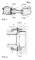
- Fig. 1 shows in cross section the connected arrangement of a rotor hub 11 with a rotor shaft 12 and a connecting part 13 of a corresponding gear of a wind turbine.
- the rotor hub 11, the rotor shaft 12 and the transmission not further detailed in the sectional view, which has the connecting part 13 in the front region, are parts of a schematically designated wind turbine WEA.
- the rotor shaft 12 is connected to the connecting part 13 of the transmission by means of a flange connection 14.
- the rotor shaft 12 at the end facing the connecting part 13 on a flange 15, which has corresponding holes 16 for receiving screws.
- the holes 16 are arranged regularly over the circumference of the flange 15.
- the connecting part 13 of the transmission has on the rotor shaft 12 side facing blind holes 17 which have corresponding thread. From the rotor shaft side screws 18 are threadedly inserted into the bores 16 of the rotor shaft 12 and the bores 17 of the connecting part 13, so that the rotor shaft 12 is connected to the connecting part 13 to form a bias voltage.
- connecting intermediate bodies 20 are arranged in the region of the bores 16, 17, which are detachably located between the rotor shaft 12 and the connecting part 13.
- the connecting intermediate bodies 20 are provided according to the invention with a friction-increasing coating on both sides of the rotor shaft 12 and the connecting part 13, so that by tightening the screws 18, the coefficient of friction and the frictional engagement between the rotor shaft 12 and the connecting part 13 is increased or is.
- connection intermediate body 20 When disassembling, ie releasing the connection between the rotor shaft 12 and the connecting part 13 by unscrewing the screws 18, it is possible that the connecting intermediate body 20 can be removed manually on the detachable connection between the two components.
- the contact surfaces of the rotor shaft 12 and the connecting part 13, which face each other, can both coated and untreated, ie smooth.
- the connection intermediate bodies 20 are provided with a coating of hard particles, such as diamond, wherein the particle size is greater than 30 microns, preferably more than 35 microns.
- the intermediate connecting bodies 20 are preferably galvanically nickel-coated with a mean particle size of 46 ⁇ m (diamond D46).
- the ends of the rotor shaft 12 and the connecting part 13 are larger in diameter than 0.5 m.
- Fig. 3a is still a detailed view of the connection between the rotor shaft 12 and the rotor hub 11 (see. Fig. 1 ) shown in cross section.
- the rotor hub 11 has on its inner side via a flange 19 with corresponding holes in which bolts or screws are used and connected to the front side of the rotor shaft 12.
- corresponding blind bores for receiving the screws or bolts are provided on the rotor shaft 12.
- a flange 21 is provided with corresponding holes for receiving bolts or screws to form a mutual flange on the rotor shaft 12.
- the bolts are inserted into the bores of the flange ring 21, so that the bolts or screws pass correspondingly formed (blind holes or through holes) on the rotor hub 11, whereby the bolts of the outer row of the flange ring 21 are arranged opposite to the bolts of the inner row of the flange 19 of the rotor hub 11.
- the bolt circle of the holes of the flange ring 21 larger than the bolt circle of the holes of the flange 19th
- this makes possible a double-row threaded flange connection of the two components subjected to high mechanical stress, the assembly being effected by aligning the rotor hub and the rotor shaft with each other, then screwing the row of bolts on the outer flange ring 21 of the rotor shaft 12 and thereafter the connecting elements in FIG Form of bolts or screws in the interior of the rotor hub 11 are screwed to the inner flange 19. Subsequently, the bolts or screws are clamped with a predetermined biasing force. As a result, a robust flange connection of the rotor hub 11 with the rotor shaft 12 is made possible.
- a track 24 is arranged, which acts as a contact track for a (not shown) lightning conductor.
- intermediate body 20 By connecting intermediate body 20 according to the invention with their reibwerterhöenden coatings on both sides of Components, rotor hub 11 and rotor shaft 12, an arrangement for preventing relative movements between the mutually braced frictionally cooperating components (rotor hub 11 and rotor shaft 12) is achieved.
- the rotor hub 11 is a cast component, e.g. Nodular cast iron, or of simple structural steel, wherein the contact surface of the flange ring 20 to the rotor hub preferably mechanically smooth, e.g. RZ 16, has been processed.
- the rotor shaft 12 is designed as a second component as a steel component (mild steel or tempered steel) or as a cast component.
- the contact surface with the rotor hub 11 may be sandblasted, e.g. SA3, wherein the surface may also be cured in further embodiments.
- the bias applied by the connecting elements or bolts between the rotor shaft 12 and the rotor hub 11 should reach surface pressures in the range of 60 to 220 N / mm 2 , preferably between 90 and 200 N / mm 2 , at the contact surfaces.
- surface pressures in the range of 60 to 220 N / mm 2 , preferably between 90 and 200 N / mm 2 , at the contact surfaces.
- Fig. 3b Furthermore, the view is shown on the flange 19 of the rotor hub 11. It can be seen that the holes of the flange 19 are arranged in a circle, wherein the connection region of the rotor hub 11 to the rotor shaft on the flange 19 has a diameter of more than 0.5 m in general.
- connecting intermediate bodies 20 are simultaneously used as a locking disk for a rotor lock.
- the locking disc consists of three identical segments, which are designed as connecting intermediate body 20.
- the locking takes place via two locking devices 26, in which bolts, not shown, are pushed by the bolt receivers 27.
- a total of 12 bolt receivers 27 are positioned so that each rotor blade can be locked in a vertical and horizontal position.
- the three recesses 28 in the locking disc allow the maintenance personnel a passage in the rotor hub cover. It is particularly economical if the locking disc is made from remnants of the machine frame production.
- the rotor hub shroud (not shown) is preferably attached to the intermediate elements 20 so as not to disturb the flow of power in the rotor hub by additional fasteners (sprues).
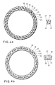
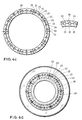
- FIGS. 4a to 4d various embodiments of the arrangement of connecting intermediate body 20 on a component or on a flange of a component in a view are shown, wherein in the FIGS. 4a to 4c in the left area in each case a circular arrangement of the connecting intermediate body 20 and in the right region of the figures in each case a single view of the intermediate connecting body 20 is shown.
- the connecting intermediate bodies 20 are, for example, about 5 mm thick and 200 to 600 mm long. Smaller elements reduce the coating costs, but increase the assembly costs, so that in individual cases, the exact dimensions are adapted to the respective preferred and predetermined application.
- connecting intermediate body 20 between the contact surfaces of two components, in particular the contact surfaces of a flange connection between the components By means of the unilaterally coated, preferably coated on both sides to the contact surfaces of components, connecting intermediate body 20 between the contact surfaces of two components, in particular the contact surfaces of a flange connection between the components, a kind of segmented ring from the intermediate connecting bodies 20 is formed.
- the connecting intermediate bodies 20 are formed as a partial segment of a circular arrangement.
- the interconnecting bodies 20 may have one or more through-holes 22, so that the connecting intermediate bodies 20 are penetrated by bolts or screws of a flange connection between two components to be connected.
- the connecting intermediate bodies 20 have smaller holes 23, so that mounting elements in the form of countersunk screws pass through the holes 23, whereby, for example, a mounting of the intermediate connecting body 20 on a flange ring is made possible or simplified.
- the connecting intermediate bodies 20 can be mounted on the contact surfaces of the components, the contact surfaces preferably having blind bores for receiving threads.
- Fig. 5 shows a further embodiment of a compound of a rotor shaft 12 with a transmission flange 130 of a transmission not shown in accordance with the in Fig. 2 shown execution.
- a locking disk 30 is arranged, which has both contact surfaces to the rotor shaft 12 and the gearbox flange 130.
- intermediate connection bodies 20 provided with a coating on the surface are arranged between the rotor shaft 12 and the lock washer 130 .
- the lock washer 30 is provided with through holes, so that schematically drawn screws 31, which are used on the Geretefllanschseite, a washer 32 and the locking holes 30 and provided through holes of the intermediate connecting body 20 pass through and open in blind holes of the rotor shaft 12.
- connecting intermediate body 20 are arranged between the locking disk 30 and the gearbox flange 130, so that the geared flange 130 and the locking disk 30 are connected to schematically drawn screws 33.
- the intermediate connecting bodies 20 are hardened and / or coated connecting intermediate bodies 20 according to the invention, resulting in improved frictional connections with higher frictional engagements.
Landscapes
- Engineering & Computer Science (AREA)
- General Engineering & Computer Science (AREA)
- Mechanical Engineering (AREA)
- Life Sciences & Earth Sciences (AREA)
- Sustainable Development (AREA)
- Sustainable Energy (AREA)
- Chemical & Material Sciences (AREA)
- Combustion & Propulsion (AREA)
- Wind Motors (AREA)
- Lining Or Joining Of Plastics Or The Like (AREA)
- Turbine Rotor Nozzle Sealing (AREA)
Applications Claiming Priority (2)
| Application Number | Priority Date | Filing Date | Title |
|---|---|---|---|
| DE102007014861.7A DE102007014861C5 (de) | 2007-03-26 | 2007-03-26 | Verbindung von Bauteilen einer Windenergieanlage |
| EP08716308.5A EP2126353B2 (fr) | 2007-03-26 | 2008-03-06 | Assemblage de composants d'une éolienne et procédé |
Related Parent Applications (3)
| Application Number | Title | Priority Date | Filing Date |
|---|---|---|---|
| EP08716308.5 Division | 2008-03-06 | ||
| EP08716308.5A Division EP2126353B2 (fr) | 2007-03-26 | 2008-03-06 | Assemblage de composants d'une éolienne et procédé |
| EP08716308.5A Division-Into EP2126353B2 (fr) | 2007-03-26 | 2008-03-06 | Assemblage de composants d'une éolienne et procédé |
Publications (3)
| Publication Number | Publication Date |
|---|---|
| EP2444662A1 true EP2444662A1 (fr) | 2012-04-25 |
| EP2444662B1 EP2444662B1 (fr) | 2014-10-29 |
| EP2444662B2 EP2444662B2 (fr) | 2017-11-29 |
Family
ID=39719399
Family Applications (2)
| Application Number | Title | Priority Date | Filing Date |
|---|---|---|---|
| EP12151703.1A Active EP2444662B2 (fr) | 2007-03-26 | 2008-03-06 | Liaison de composants d'une éolienne |
| EP08716308.5A Active EP2126353B2 (fr) | 2007-03-26 | 2008-03-06 | Assemblage de composants d'une éolienne et procédé |
Family Applications After (1)
| Application Number | Title | Priority Date | Filing Date |
|---|---|---|---|
| EP08716308.5A Active EP2126353B2 (fr) | 2007-03-26 | 2008-03-06 | Assemblage de composants d'une éolienne et procédé |
Country Status (8)
| Country | Link |
|---|---|
| US (1) | US20100171317A1 (fr) |
| EP (2) | EP2444662B2 (fr) |
| CN (1) | CN101663482B (fr) |
| AT (1) | ATE544004T1 (fr) |
| DE (1) | DE102007014861C5 (fr) |
| DK (2) | DK2126353T4 (fr) |
| ES (2) | ES2378910T5 (fr) |
| WO (1) | WO2008116549A2 (fr) |
Families Citing this family (33)
| Publication number | Priority date | Publication date | Assignee | Title |
|---|---|---|---|---|
| DE102007014861C5 (de) † | 2007-03-26 | 2024-06-20 | Siemens Gamesa Renewable Energy Service Gmbh | Verbindung von Bauteilen einer Windenergieanlage |
| EP2075466B8 (fr) | 2007-12-28 | 2012-04-04 | Gamesa Innovation & Technology, S.L. | Procédé pour le raccordement de l' arbre principal à vitesse réduite d'une éolienne sur l'arbre d'entrée de la boîte de vitesse de l'éolienne et dispositif de liaison selon ledit procédé |
| DE102008053222A1 (de) * | 2008-10-25 | 2010-04-29 | Bosch Mahle Turbo Systems Gmbh & Co. Kg | Turbolader |
| DE102008055706A1 (de) * | 2008-11-03 | 2010-05-06 | Volkswagen Ag | Vorrichtung zur Befestigung eines Rades auf einer Welle |
| DE102009032239A1 (de) * | 2009-07-08 | 2011-03-24 | Aktiebolaget Skf | Wellenkupplung einer Wasserkraftanlage |
| DE102010004662B4 (de) * | 2010-01-14 | 2014-12-24 | Siemens Aktiengesellschaft | Bor basierte Hartstoffbeschichtung einer Windkraftanlagenkomponente |
| DE102010004661B4 (de) * | 2010-01-14 | 2014-12-24 | Siemens Aktiengesellschaft | Vanadium basierte Hartstoffbeschichtung einer Windkraftanlagenkomponente |
| US8556591B2 (en) * | 2010-04-21 | 2013-10-15 | General Electric Company | Systems and methods for assembling a rotor lock assembly for use in a wind turbine |
| DE102010039628A1 (de) * | 2010-08-20 | 2012-02-23 | Ssb Service Gmbh | Rotorarretiervorrichtung und Verfahren zum Arretieren eines Rotors einer Windenergieanlage |
| DE102011002488A1 (de) * | 2011-01-10 | 2012-07-12 | Repower Systems Se | Anordnung von Bauteilen einer Windenergieanlage |
| AT510694B1 (de) * | 2011-01-21 | 2012-06-15 | Hexcel Holding Gmbh | Modul zum halten von mindestens einer hülse |
| CN203498471U (zh) | 2011-01-28 | 2014-03-26 | 维斯塔斯风力系统有限公司 | 具有防腐蚀结构的风力涡轮机叶片和使用该叶片的风力涡轮机 |
| DE102011085612A1 (de) * | 2011-11-02 | 2013-05-02 | Aktiebolaget Skf | Reibscheibenkomponente, Anordnung und Unterwasserkraftwerk |
| CN103182667A (zh) * | 2011-12-29 | 2013-07-03 | 自贡市江阳磁材有限责任公司 | 通过式磁瓦磨床电镀金刚石耐磨防窜瓦工装 |
| ES2596408T3 (es) * | 2012-01-24 | 2017-01-09 | Nordex Energy Gmbh | Dispositivo de detención para un tren de potencia de un aerogenerador |
| DE102012211263B4 (de) * | 2012-06-29 | 2014-02-27 | Aktiebolaget Skf | Maschinenanordnung |
| DE102012212295B4 (de) * | 2012-07-13 | 2014-08-21 | Aktiebolaget Skf | Verfahren zum Erzeugen einer ein Drehmoment übertragenden Verbindung und drehmomentübertragende Anordnung |
| KR101466100B1 (ko) * | 2013-08-23 | 2014-12-09 | 삼성중공업 주식회사 | 풍력 발전기 |
| DE102013223174A1 (de) * | 2013-11-14 | 2015-06-03 | Aktiebolaget Skf | Gezeitenströmungskraftanlage |
| CN103615360B (zh) * | 2013-11-30 | 2016-06-15 | 国家电网公司 | 风力发电机及其主轴与轮毂连接结构 |
| CN103994176B (zh) * | 2014-05-27 | 2015-12-09 | 上海思博特轴承技术研发有限公司 | 汽车轮毂轴承内法兰动静平衡的调节工艺及其法兰组件 |
| US9657782B2 (en) * | 2015-04-29 | 2017-05-23 | Ford Motor Company | Method and apparatus for assembling a driveshaft flange to a transmission flange |
| US9970304B2 (en) | 2015-07-22 | 2018-05-15 | General Electric Company | Rotor blade root assembly for a wind turbine |
| US10060411B2 (en) | 2015-07-22 | 2018-08-28 | General Electric Company | Rotor blade root assembly for a wind turbine |
| EP3130797A1 (fr) * | 2015-08-13 | 2017-02-15 | LM WP Patent Holding A/S | Pale d'éolienne dotée de brides d'extrémité |
| DE102016005019A1 (de) * | 2016-04-26 | 2017-10-26 | Senvion Gmbh | Schraubverbindung |
| DE102017004056A1 (de) * | 2017-04-27 | 2018-10-31 | Senvion Gmbh | Blattadapter für Windenergieanlagen |
| EP3450775B1 (fr) | 2017-08-28 | 2022-03-09 | 3M Innovative Properties Company | Élément de connexion augmentant la friction de connexion des composants, procédé de fixation d'un élément de connexion et utilisation d'un élément de connexion |
| EP3775538B1 (fr) | 2018-03-28 | 2023-06-14 | Vestas Wind Systems A/S | Système de liaison destiné à assembler des éléments d'éolienne, et procédé associé |
| EP3663436A1 (fr) * | 2018-12-05 | 2020-06-10 | 3M Innovative Properties Company | Élément de connexion augmentant la friction de connexion des composants, procédé de fabrication d'un élément de connexion et utilisation d'un élément de connexion |
| US11873794B2 (en) * | 2018-12-20 | 2024-01-16 | Vestas Wind Systems A/S | Generator-gearbox assembly for a wind turbine |
| CN115263660B (zh) * | 2022-08-01 | 2025-10-28 | 三一重能股份有限公司 | 风力发电叶片装置和风力发电设备 |
| EP4520953B1 (fr) * | 2023-09-11 | 2026-02-04 | Siemens Gamesa Renewable Energy A/S | Éolienne |
Citations (10)
| Publication number | Priority date | Publication date | Assignee | Title |
|---|---|---|---|---|
| US2879092A (en) * | 1957-12-13 | 1959-03-24 | Gen Electric | Friction shaft-coupling assembly |
| DE3237096A1 (de) * | 1982-10-07 | 1984-04-12 | Mannesmann AG, 4000 Düsseldorf | Drehfeste verbindung |
| DE8625580U1 (de) * | 1986-09-25 | 1986-11-06 | J.M. Voith Gmbh, 7920 Heidenheim | Flanschkupplung |
| EP0961038A1 (fr) * | 1998-05-28 | 1999-12-01 | Elektroschmelzwerk Kempten GmbH | Elément pour la connection des éléments par friction |
| DE10119427A1 (de) * | 2001-04-20 | 2002-10-24 | Enron Wind Gmbh | Kopplungsvorrichtung für eine Windkraftanlage |
| DE10134809A1 (de) * | 2001-07-17 | 2003-02-06 | Fischer Artur Werke Gmbh | Reibkraftverstärker |
| EP1302685A1 (fr) * | 2001-10-11 | 2003-04-16 | Wacker-Chemie GmbH | Anneau de tolérance avec revêtement de frottement |
| US6713891B2 (en) * | 1998-12-17 | 2004-03-30 | Dan-Control Engineering A/S | Wind mill with a suspension for cables and the like, such suspension for cables and the like and a holder for such suspension |
| DE102005011023A1 (de) * | 2005-03-10 | 2006-09-14 | Knut Schwedler | Windenergieanlage |
| DE102006009616A1 (de) * | 2006-03-02 | 2007-09-06 | Deutz Ag | Gegeneinander verspannte Bauteile |
Family Cites Families (14)
| Publication number | Priority date | Publication date | Assignee | Title |
|---|---|---|---|---|
| US2617672A (en) * | 1948-06-23 | 1952-11-11 | Harry J Nichols | Coupling |
| ES438990A1 (es) * | 1974-09-30 | 1977-02-01 | Gen Electric | Perfeccionamientos en acoplamientos terminales de colector para maquinas dinamoelectricas. |
| DK168834B1 (da) † | 1992-06-03 | 1994-06-20 | Man B & W Diesel Gmbh | Tætningsorgan |
| US5466105A (en) * | 1994-06-09 | 1995-11-14 | Westinghouse Air Brake Company | Fastener assembly for installing valve devices and the like |
| US6347905B1 (en) | 1998-05-28 | 2002-02-19 | Elektroschmelzwerk Kempten Gmbh | Connecting element for the frictional connection of components |
| US6167992B1 (en) * | 1998-07-14 | 2001-01-02 | Alliedsignal Inc. | Abrasive coating on brake pads |
| DE19832921A1 (de) * | 1998-07-22 | 2000-02-10 | Joachim Kretz | Turmkonstruktion, insbesondere für Windkraftanlagen |
| DE19962978C1 (de) * | 1999-12-24 | 2001-08-30 | Aloys Wobben | Windenergieanlage mit einem turmgestützten Maschinenkopf |
| US6514147B2 (en) * | 2000-06-05 | 2003-02-04 | Unisia Jecs Corporation | Flexible shaft coupling for vehicles |
| DE10231948A1 (de) * | 2002-07-15 | 2004-01-29 | Ge Wind Energy Gmbh | Windenergieanlage und Lageranordnung dafür |
| JP4156976B2 (ja) * | 2003-06-03 | 2008-09-24 | 株式会社ブリヂストン | タイヤ成型ドラムの連結装置 |
| JP2006046107A (ja) * | 2004-08-02 | 2006-02-16 | Yanmar Co Ltd | 風力発電装置 |
| DE102007014861C5 (de) † | 2007-03-26 | 2024-06-20 | Siemens Gamesa Renewable Energy Service Gmbh | Verbindung von Bauteilen einer Windenergieanlage |
| EP2961038B1 (fr) * | 2014-06-05 | 2019-12-11 | Samsung Electronics Co., Ltd. | Aspirateur avec ensemble de moteur |
-
2007
- 2007-03-26 DE DE102007014861.7A patent/DE102007014861C5/de active Active
-
2008
- 2008-03-06 EP EP12151703.1A patent/EP2444662B2/fr active Active
- 2008-03-06 DK DK08716308.5T patent/DK2126353T4/da active
- 2008-03-06 US US12/593,198 patent/US20100171317A1/en not_active Abandoned
- 2008-03-06 AT AT08716308T patent/ATE544004T1/de active
- 2008-03-06 ES ES08716308.5T patent/ES2378910T5/es active Active
- 2008-03-06 CN CN2008800097993A patent/CN101663482B/zh active Active
- 2008-03-06 ES ES12151703.1T patent/ES2527038T5/es active Active
- 2008-03-06 WO PCT/EP2008/001793 patent/WO2008116549A2/fr not_active Ceased
- 2008-03-06 DK DK12151703.1T patent/DK2444662T4/en active
- 2008-03-06 EP EP08716308.5A patent/EP2126353B2/fr active Active
Patent Citations (10)
| Publication number | Priority date | Publication date | Assignee | Title |
|---|---|---|---|---|
| US2879092A (en) * | 1957-12-13 | 1959-03-24 | Gen Electric | Friction shaft-coupling assembly |
| DE3237096A1 (de) * | 1982-10-07 | 1984-04-12 | Mannesmann AG, 4000 Düsseldorf | Drehfeste verbindung |
| DE8625580U1 (de) * | 1986-09-25 | 1986-11-06 | J.M. Voith Gmbh, 7920 Heidenheim | Flanschkupplung |
| EP0961038A1 (fr) * | 1998-05-28 | 1999-12-01 | Elektroschmelzwerk Kempten GmbH | Elément pour la connection des éléments par friction |
| US6713891B2 (en) * | 1998-12-17 | 2004-03-30 | Dan-Control Engineering A/S | Wind mill with a suspension for cables and the like, such suspension for cables and the like and a holder for such suspension |
| DE10119427A1 (de) * | 2001-04-20 | 2002-10-24 | Enron Wind Gmbh | Kopplungsvorrichtung für eine Windkraftanlage |
| DE10134809A1 (de) * | 2001-07-17 | 2003-02-06 | Fischer Artur Werke Gmbh | Reibkraftverstärker |
| EP1302685A1 (fr) * | 2001-10-11 | 2003-04-16 | Wacker-Chemie GmbH | Anneau de tolérance avec revêtement de frottement |
| DE102005011023A1 (de) * | 2005-03-10 | 2006-09-14 | Knut Schwedler | Windenergieanlage |
| DE102006009616A1 (de) * | 2006-03-02 | 2007-09-06 | Deutz Ag | Gegeneinander verspannte Bauteile |
Also Published As
| Publication number | Publication date |
|---|---|
| ATE544004T1 (de) | 2012-02-15 |
| WO2008116549A2 (fr) | 2008-10-02 |
| EP2126353B1 (fr) | 2012-02-01 |
| WO2008116549A3 (fr) | 2008-12-04 |
| ES2378910T5 (es) | 2017-11-22 |
| DE102007014861A1 (de) | 2008-10-02 |
| ES2527038T3 (es) | 2015-01-19 |
| EP2126353A2 (fr) | 2009-12-02 |
| DK2444662T4 (en) | 2018-03-05 |
| EP2444662B2 (fr) | 2017-11-29 |
| ES2527038T5 (es) | 2018-03-08 |
| DK2126353T4 (da) | 2017-04-24 |
| DE102007014861C5 (de) | 2024-06-20 |
| EP2126353B2 (fr) | 2017-01-11 |
| ES2378910T3 (es) | 2012-04-19 |
| EP2444662B1 (fr) | 2014-10-29 |
| DK2444662T3 (en) | 2015-02-02 |
| CN101663482A (zh) | 2010-03-03 |
| DK2126353T3 (da) | 2012-04-23 |
| DE102007014861B4 (de) | 2015-07-30 |
| US20100171317A1 (en) | 2010-07-08 |
| CN101663482B (zh) | 2013-08-14 |
Similar Documents
| Publication | Publication Date | Title |
|---|---|---|
| EP2126353B1 (fr) | Assemblage de composants d'une éolienne et procédé | |
| EP1975405B1 (fr) | Raccordement des éléments d'une installation d'énergie éolienne, utilization et procédé | |
| EP2663769B1 (fr) | Agencement d'éléments d'une éolienne | |
| EP1000243B1 (fr) | Raccordement de la pale de rotor d'une eolienne a un moyeu de rotor | |
| DE102011088025A1 (de) | Rotorblatt | |
| DE10305543B4 (de) | Verfahren zur Montage von Rotorblättern sowie ein Rotorblatt für eine Windenergieanlage | |
| DE10324166B4 (de) | Rotorblattanschluss | |
| EP2280191A2 (fr) | Unité d'entraînement dotée d'une protection contre les surcharges pour l'entraînement d'une couronne dentée, set comprenant plusieurs telles unités et dispositif comprenant une telle unité | |
| EP3929431B1 (fr) | Module et procédé de raccordement de deux segments de pale de rotor d'une pale de rotor d'éolienne | |
| EP3559417B1 (fr) | Procédé de fabrication d'une pale de rotor d'éolienne et pale de rotor d'éolienne | |
| DE102017106875B4 (de) | Windkraftanlage und Verfahren zu dessen Montage | |
| EP3423706B1 (fr) | Éolienne à vissage amélioré de pale de rotor | |
| EP2434143A2 (fr) | Pale de rotor ou segment d'une pale de rotor pour une éolienne | |
| EP3204633B1 (fr) | Pale de rotor d'éolienne | |
| EP4291790B1 (fr) | Dispositif d'entraînement et/ou de réglage à protection contre les surcharges | |
| DE102012009362A1 (de) | Optimiertes Generatorgetriebe einer Windkraftanlage | |
| EP2036816A2 (fr) | Raccordement amovible par complémentarité de forme et de force d'un corps de base doté d'un composant installé de manière rotative | |
| WO2020058104A1 (fr) | Système de palier de pale pour une éolienne, éolienne et procédé de fabrication d'un système de palier de pale | |
| EP4667739A1 (fr) | Installation eolienne | |
| DE102023106818A1 (de) | Lagerbuchse, Lagerbuchsenanordnung und Windenergieanlagenlager für Windenergieanlagen | |
| DE102015119684A1 (de) | Welle zum Übertragen von Drehmomenten |
Legal Events
| Date | Code | Title | Description |
|---|---|---|---|
| 17P | Request for examination filed |
Effective date: 20120119 |
|
| AC | Divisional application: reference to earlier application |
Ref document number: 2126353 Country of ref document: EP Kind code of ref document: P |
|
| AK | Designated contracting states |
Kind code of ref document: A1 Designated state(s): AT BE BG CH CY CZ DE DK EE ES FI FR GB GR HR HU IE IS IT LI LT LU LV MC MT NL NO PL PT RO SE SI SK TR |
|
| PUAI | Public reference made under article 153(3) epc to a published international application that has entered the european phase |
Free format text: ORIGINAL CODE: 0009012 |
|
| GRAP | Despatch of communication of intention to grant a patent |
Free format text: ORIGINAL CODE: EPIDOSNIGR1 |
|
| INTG | Intention to grant announced |
Effective date: 20140708 |
|
| GRAS | Grant fee paid |
Free format text: ORIGINAL CODE: EPIDOSNIGR3 |
|
| GRAA | (expected) grant |
Free format text: ORIGINAL CODE: 0009210 |
|
| RAP1 | Party data changed (applicant data changed or rights of an application transferred) |
Owner name: SENVION SE |
|
| AC | Divisional application: reference to earlier application |
Ref document number: 2126353 Country of ref document: EP Kind code of ref document: P |
|
| AK | Designated contracting states |
Kind code of ref document: B1 Designated state(s): AT BE BG CH CY CZ DE DK EE ES FI FR GB GR HR HU IE IS IT LI LT LU LV MC MT NL NO PL PT RO SE SI SK TR |
|
| REG | Reference to a national code |
Ref country code: GB Ref legal event code: FG4D Free format text: NOT ENGLISH |
|
| REG | Reference to a national code |
Ref country code: CH Ref legal event code: EP |
|
| REG | Reference to a national code |
Ref country code: AT Ref legal event code: REF Ref document number: 693749 Country of ref document: AT Kind code of ref document: T Effective date: 20141115 |
|
| REG | Reference to a national code |
Ref country code: IE Ref legal event code: FG4D Free format text: LANGUAGE OF EP DOCUMENT: GERMAN |
|
| RAP2 | Party data changed (patent owner data changed or rights of a patent transferred) |
Owner name: SENVION SE |
|
| REG | Reference to a national code |
Ref country code: DE Ref legal event code: R096 Ref document number: 502008012362 Country of ref document: DE Effective date: 20141211 |
|
| REG | Reference to a national code |
Ref country code: ES Ref legal event code: FG2A Ref document number: 2527038 Country of ref document: ES Kind code of ref document: T3 Effective date: 20150119 |
|
| REG | Reference to a national code |
Ref country code: DK Ref legal event code: T3 Effective date: 20150128 |
|
| REG | Reference to a national code |
Ref country code: NL Ref legal event code: VDEP Effective date: 20141029 |
|
| REG | Reference to a national code |
Ref country code: LT Ref legal event code: MG4D |
|
| PG25 | Lapsed in a contracting state [announced via postgrant information from national office to epo] |
Ref country code: NL Free format text: LAPSE BECAUSE OF FAILURE TO SUBMIT A TRANSLATION OF THE DESCRIPTION OR TO PAY THE FEE WITHIN THE PRESCRIBED TIME-LIMIT Effective date: 20141029 Ref country code: PT Free format text: LAPSE BECAUSE OF FAILURE TO SUBMIT A TRANSLATION OF THE DESCRIPTION OR TO PAY THE FEE WITHIN THE PRESCRIBED TIME-LIMIT Effective date: 20150302 Ref country code: NO Free format text: LAPSE BECAUSE OF FAILURE TO SUBMIT A TRANSLATION OF THE DESCRIPTION OR TO PAY THE FEE WITHIN THE PRESCRIBED TIME-LIMIT Effective date: 20150129 Ref country code: IS Free format text: LAPSE BECAUSE OF FAILURE TO SUBMIT A TRANSLATION OF THE DESCRIPTION OR TO PAY THE FEE WITHIN THE PRESCRIBED TIME-LIMIT Effective date: 20150228 Ref country code: LT Free format text: LAPSE BECAUSE OF FAILURE TO SUBMIT A TRANSLATION OF THE DESCRIPTION OR TO PAY THE FEE WITHIN THE PRESCRIBED TIME-LIMIT Effective date: 20141029 Ref country code: FI Free format text: LAPSE BECAUSE OF FAILURE TO SUBMIT A TRANSLATION OF THE DESCRIPTION OR TO PAY THE FEE WITHIN THE PRESCRIBED TIME-LIMIT Effective date: 20141029 |
|
| PG25 | Lapsed in a contracting state [announced via postgrant information from national office to epo] |
Ref country code: SE Free format text: LAPSE BECAUSE OF FAILURE TO SUBMIT A TRANSLATION OF THE DESCRIPTION OR TO PAY THE FEE WITHIN THE PRESCRIBED TIME-LIMIT Effective date: 20141029 Ref country code: CY Free format text: LAPSE BECAUSE OF FAILURE TO SUBMIT A TRANSLATION OF THE DESCRIPTION OR TO PAY THE FEE WITHIN THE PRESCRIBED TIME-LIMIT Effective date: 20141029 Ref country code: HR Free format text: LAPSE BECAUSE OF FAILURE TO SUBMIT A TRANSLATION OF THE DESCRIPTION OR TO PAY THE FEE WITHIN THE PRESCRIBED TIME-LIMIT Effective date: 20141029 Ref country code: PL Free format text: LAPSE BECAUSE OF FAILURE TO SUBMIT A TRANSLATION OF THE DESCRIPTION OR TO PAY THE FEE WITHIN THE PRESCRIBED TIME-LIMIT Effective date: 20141029 Ref country code: LV Free format text: LAPSE BECAUSE OF FAILURE TO SUBMIT A TRANSLATION OF THE DESCRIPTION OR TO PAY THE FEE WITHIN THE PRESCRIBED TIME-LIMIT Effective date: 20141029 Ref country code: GR Free format text: LAPSE BECAUSE OF FAILURE TO SUBMIT A TRANSLATION OF THE DESCRIPTION OR TO PAY THE FEE WITHIN THE PRESCRIBED TIME-LIMIT Effective date: 20150130 |
|
| REG | Reference to a national code |
Ref country code: DE Ref legal event code: R026 Ref document number: 502008012362 Country of ref document: DE |
|
| PG25 | Lapsed in a contracting state [announced via postgrant information from national office to epo] |
Ref country code: RO Free format text: LAPSE BECAUSE OF FAILURE TO SUBMIT A TRANSLATION OF THE DESCRIPTION OR TO PAY THE FEE WITHIN THE PRESCRIBED TIME-LIMIT Effective date: 20141029 Ref country code: EE Free format text: LAPSE BECAUSE OF FAILURE TO SUBMIT A TRANSLATION OF THE DESCRIPTION OR TO PAY THE FEE WITHIN THE PRESCRIBED TIME-LIMIT Effective date: 20141029 Ref country code: CZ Free format text: LAPSE BECAUSE OF FAILURE TO SUBMIT A TRANSLATION OF THE DESCRIPTION OR TO PAY THE FEE WITHIN THE PRESCRIBED TIME-LIMIT Effective date: 20141029 Ref country code: SK Free format text: LAPSE BECAUSE OF FAILURE TO SUBMIT A TRANSLATION OF THE DESCRIPTION OR TO PAY THE FEE WITHIN THE PRESCRIBED TIME-LIMIT Effective date: 20141029 |
|
| PLBI | Opposition filed |
Free format text: ORIGINAL CODE: 0009260 |
|
| REG | Reference to a national code |
Ref country code: DE Ref legal event code: R082 Ref document number: 502008012362 Country of ref document: DE Representative=s name: SEEMANN & PARTNER PATENTANWAELTE MBB, DE Ref country code: DE Ref legal event code: R082 Ref document number: 502008012362 Country of ref document: DE Representative=s name: PATENTANWAELTE SEEMANN & PARTNER, DE Ref country code: DE Ref legal event code: R081 Ref document number: 502008012362 Country of ref document: DE Owner name: SENVION GMBH, DE Free format text: FORMER OWNER: SENVION SE, 22297 HAMBURG, DE Ref country code: DE Ref legal event code: R082 Ref document number: 502008012362 Country of ref document: DE Representative=s name: WALLINGER RICKER SCHLOTTER TOSTMANN PATENT- UN, DE |
|
| PG25 | Lapsed in a contracting state [announced via postgrant information from national office to epo] |
Ref country code: IT Free format text: LAPSE BECAUSE OF FAILURE TO SUBMIT A TRANSLATION OF THE DESCRIPTION OR TO PAY THE FEE WITHIN THE PRESCRIBED TIME-LIMIT Effective date: 20141029 |
|
| 26 | Opposition filed |
Opponent name: 3M DEUTSCHLAND GMBH Effective date: 20150728 |
|
| RAP2 | Party data changed (patent owner data changed or rights of a patent transferred) |
Owner name: SENVION GMBH |
|
| PLAX | Notice of opposition and request to file observation + time limit sent |
Free format text: ORIGINAL CODE: EPIDOSNOBS2 |
|
| PG25 | Lapsed in a contracting state [announced via postgrant information from national office to epo] |
Ref country code: LU Free format text: LAPSE BECAUSE OF FAILURE TO SUBMIT A TRANSLATION OF THE DESCRIPTION OR TO PAY THE FEE WITHIN THE PRESCRIBED TIME-LIMIT Effective date: 20150306 Ref country code: MC Free format text: LAPSE BECAUSE OF FAILURE TO SUBMIT A TRANSLATION OF THE DESCRIPTION OR TO PAY THE FEE WITHIN THE PRESCRIBED TIME-LIMIT Effective date: 20141029 |
|
| REG | Reference to a national code |
Ref country code: CH Ref legal event code: PL |
|
| REG | Reference to a national code |
Ref country code: AT Ref legal event code: HC Ref document number: 693749 Country of ref document: AT Kind code of ref document: T Owner name: SENVION GMBH, DE Effective date: 20150923 |
|
| REG | Reference to a national code |
Ref country code: IE Ref legal event code: MM4A |
|
| PG25 | Lapsed in a contracting state [announced via postgrant information from national office to epo] |
Ref country code: LI Free format text: LAPSE BECAUSE OF NON-PAYMENT OF DUE FEES Effective date: 20150331 Ref country code: CH Free format text: LAPSE BECAUSE OF NON-PAYMENT OF DUE FEES Effective date: 20150331 Ref country code: IE Free format text: LAPSE BECAUSE OF NON-PAYMENT OF DUE FEES Effective date: 20150306 |
|
| PLBB | Reply of patent proprietor to notice(s) of opposition received |
Free format text: ORIGINAL CODE: EPIDOSNOBS3 |
|
| PG25 | Lapsed in a contracting state [announced via postgrant information from national office to epo] |
Ref country code: SI Free format text: LAPSE BECAUSE OF FAILURE TO SUBMIT A TRANSLATION OF THE DESCRIPTION OR TO PAY THE FEE WITHIN THE PRESCRIBED TIME-LIMIT Effective date: 20141029 |
|
| REG | Reference to a national code |
Ref country code: FR Ref legal event code: PLFP Year of fee payment: 9 |
|
| REG | Reference to a national code |
Ref country code: AT Ref legal event code: MM01 Ref document number: 693749 Country of ref document: AT Kind code of ref document: T Effective date: 20150306 |
|
| PLAB | Opposition data, opponent's data or that of the opponent's representative modified |
Free format text: ORIGINAL CODE: 0009299OPPO |
|
| PG25 | Lapsed in a contracting state [announced via postgrant information from national office to epo] |
Ref country code: AT Free format text: LAPSE BECAUSE OF NON-PAYMENT OF DUE FEES Effective date: 20150306 |
|
| R26 | Opposition filed (corrected) |
Opponent name: 3M DEUTSCHLAND GMBH Effective date: 20150728 |
|
| PG25 | Lapsed in a contracting state [announced via postgrant information from national office to epo] |
Ref country code: MT Free format text: LAPSE BECAUSE OF FAILURE TO SUBMIT A TRANSLATION OF THE DESCRIPTION OR TO PAY THE FEE WITHIN THE PRESCRIBED TIME-LIMIT Effective date: 20141029 |
|
| REG | Reference to a national code |
Ref country code: FR Ref legal event code: PLFP Year of fee payment: 10 |
|
| PG25 | Lapsed in a contracting state [announced via postgrant information from national office to epo] |
Ref country code: BG Free format text: LAPSE BECAUSE OF FAILURE TO SUBMIT A TRANSLATION OF THE DESCRIPTION OR TO PAY THE FEE WITHIN THE PRESCRIBED TIME-LIMIT Effective date: 20141029 Ref country code: HU Free format text: LAPSE BECAUSE OF FAILURE TO SUBMIT A TRANSLATION OF THE DESCRIPTION OR TO PAY THE FEE WITHIN THE PRESCRIBED TIME-LIMIT; INVALID AB INITIO Effective date: 20080306 |
|
| APBM | Appeal reference recorded |
Free format text: ORIGINAL CODE: EPIDOSNREFNO |
|
| APBP | Date of receipt of notice of appeal recorded |
Free format text: ORIGINAL CODE: EPIDOSNNOA2O |
|
| APAH | Appeal reference modified |
Free format text: ORIGINAL CODE: EPIDOSCREFNO |
|
| PG25 | Lapsed in a contracting state [announced via postgrant information from national office to epo] |
Ref country code: BE Free format text: LAPSE BECAUSE OF NON-PAYMENT OF DUE FEES Effective date: 20150331 |
|
| PG25 | Lapsed in a contracting state [announced via postgrant information from national office to epo] |
Ref country code: TR Free format text: LAPSE BECAUSE OF FAILURE TO SUBMIT A TRANSLATION OF THE DESCRIPTION OR TO PAY THE FEE WITHIN THE PRESCRIBED TIME-LIMIT Effective date: 20141029 |
|
| APBU | Appeal procedure closed |
Free format text: ORIGINAL CODE: EPIDOSNNOA9O |
|
| RIC2 | Information provided on ipc code assigned after grant |
Ipc: F03D 15/00 20160101AFI20170919BHEP |
|
| PUAH | Patent maintained in amended form |
Free format text: ORIGINAL CODE: 0009272 |
|
| STAA | Information on the status of an ep patent application or granted ep patent |
Free format text: STATUS: PATENT MAINTAINED AS AMENDED |
|
| 27A | Patent maintained in amended form |
Effective date: 20171129 |
|
| AK | Designated contracting states |
Kind code of ref document: B2 Designated state(s): AT BE BG CH CY CZ DE DK EE ES FI FR GB GR HR HU IE IS IT LI LT LU LV MC MT NL NO PL PT RO SE SI SK TR |
|
| REG | Reference to a national code |
Ref country code: DE Ref legal event code: R102 Ref document number: 502008012362 Country of ref document: DE |
|
| REG | Reference to a national code |
Ref country code: DE Ref legal event code: R082 Ref document number: 502008012362 Country of ref document: DE Representative=s name: WALLINGER RICKER SCHLOTTER TOSTMANN PATENT- UN, DE |
|
| REG | Reference to a national code |
Ref country code: DK Ref legal event code: T4 Effective date: 20180226 |
|
| REG | Reference to a national code |
Ref country code: ES Ref legal event code: DC2A Ref document number: 2527038 Country of ref document: ES Kind code of ref document: T5 Effective date: 20180308 |
|
| REG | Reference to a national code |
Ref country code: FR Ref legal event code: PLFP Year of fee payment: 11 |
|
| PG25 | Lapsed in a contracting state [announced via postgrant information from national office to epo] |
Ref country code: LV Free format text: LAPSE BECAUSE OF FAILURE TO SUBMIT A TRANSLATION OF THE DESCRIPTION OR TO PAY THE FEE WITHIN THE PRESCRIBED TIME-LIMIT Effective date: 20141029 |
|
| REG | Reference to a national code |
Ref country code: DE Ref legal event code: R081 Ref document number: 502008012362 Country of ref document: DE Owner name: SIEMENS GAMESA RENEWABLE ENERGY SERVICE GMBH, DE Free format text: FORMER OWNER: SENVION GMBH, 22297 HAMBURG, DE |
|
| P01 | Opt-out of the competence of the unified patent court (upc) registered |
Effective date: 20230530 |
|
| REG | Reference to a national code |
Ref country code: GB Ref legal event code: 732E Free format text: REGISTERED BETWEEN 20230727 AND 20230802 |
|
| PGFP | Annual fee paid to national office [announced via postgrant information from national office to epo] |
Ref country code: DE Payment date: 20250327 Year of fee payment: 18 |
|
| PGFP | Annual fee paid to national office [announced via postgrant information from national office to epo] |
Ref country code: DK Payment date: 20250325 Year of fee payment: 18 |
|
| PGFP | Annual fee paid to national office [announced via postgrant information from national office to epo] |
Ref country code: FR Payment date: 20250324 Year of fee payment: 18 |
|
| PGFP | Annual fee paid to national office [announced via postgrant information from national office to epo] |
Ref country code: GB Payment date: 20250325 Year of fee payment: 18 |
|
| PGFP | Annual fee paid to national office [announced via postgrant information from national office to epo] |
Ref country code: ES Payment date: 20250415 Year of fee payment: 18 |