EP2444752A2 - Composant de guidage d'air pour un système de répartition d'air, système de répartition d'air pour bâtiments dotés de ce composant, procédé destiné à l'agencement du composant de guidage d'air ainsi que procédé de fonctionnement d'un système de répartition d'air - Google Patents
Composant de guidage d'air pour un système de répartition d'air, système de répartition d'air pour bâtiments dotés de ce composant, procédé destiné à l'agencement du composant de guidage d'air ainsi que procédé de fonctionnement d'un système de répartition d'air Download PDFInfo
- Publication number
- EP2444752A2 EP2444752A2 EP11008349A EP11008349A EP2444752A2 EP 2444752 A2 EP2444752 A2 EP 2444752A2 EP 11008349 A EP11008349 A EP 11008349A EP 11008349 A EP11008349 A EP 11008349A EP 2444752 A2 EP2444752 A2 EP 2444752A2
- Authority
- EP
- European Patent Office
- Prior art keywords
- air
- cover
- feet
- serves
- cavity
- Prior art date
- Legal status (The legal status is an assumption and is not a legal conclusion. Google has not performed a legal analysis and makes no representation as to the accuracy of the status listed.)
- Granted
Links
- 238000000034 method Methods 0.000 title claims abstract description 20
- 238000009423 ventilation Methods 0.000 title description 21
- 238000009826 distribution Methods 0.000 claims description 60
- 230000000712 assembly Effects 0.000 claims description 33
- 238000000429 assembly Methods 0.000 claims description 33
- 239000000463 material Substances 0.000 claims description 9
- 239000004033 plastic Substances 0.000 claims description 8
- 229920003023 plastic Polymers 0.000 claims description 8
- 125000006850 spacer group Chemical group 0.000 claims description 8
- -1 polyethylene Polymers 0.000 claims description 4
- 239000004698 Polyethylene Substances 0.000 claims description 2
- 239000004743 Polypropylene Substances 0.000 claims description 2
- 239000006260 foam Substances 0.000 claims description 2
- NJPPVKZQTLUDBO-UHFFFAOYSA-N novaluron Chemical compound C1=C(Cl)C(OC(F)(F)C(OC(F)(F)F)F)=CC=C1NC(=O)NC(=O)C1=C(F)C=CC=C1F NJPPVKZQTLUDBO-UHFFFAOYSA-N 0.000 claims description 2
- 229920000573 polyethylene Polymers 0.000 claims description 2
- 229920001155 polypropylene Polymers 0.000 claims description 2
- 239000003570 air Substances 0.000 claims 1
- 230000015572 biosynthetic process Effects 0.000 abstract description 4
- 241001074085 Scophthalmus aquosus Species 0.000 abstract 1
- 230000004308 accommodation Effects 0.000 abstract 1
- 230000008901 benefit Effects 0.000 description 64
- 238000011161 development Methods 0.000 description 20
- 230000018109 developmental process Effects 0.000 description 20
- 238000010438 heat treatment Methods 0.000 description 20
- 238000009434 installation Methods 0.000 description 14
- XLYOFNOQVPJJNP-UHFFFAOYSA-N water Substances O XLYOFNOQVPJJNP-UHFFFAOYSA-N 0.000 description 13
- 238000009408 flooring Methods 0.000 description 8
- 238000007667 floating Methods 0.000 description 6
- 239000013598 vector Substances 0.000 description 6
- 230000006978 adaptation Effects 0.000 description 5
- 238000004378 air conditioning Methods 0.000 description 5
- 230000001143 conditioned effect Effects 0.000 description 5
- 239000011505 plaster Substances 0.000 description 5
- 230000035508 accumulation Effects 0.000 description 4
- 238000009825 accumulation Methods 0.000 description 4
- 239000000853 adhesive Substances 0.000 description 4
- 230000001070 adhesive effect Effects 0.000 description 4
- 238000010276 construction Methods 0.000 description 4
- 238000003825 pressing Methods 0.000 description 4
- 238000009418 renovation Methods 0.000 description 4
- 230000004888 barrier function Effects 0.000 description 3
- 238000001816 cooling Methods 0.000 description 3
- 238000004519 manufacturing process Methods 0.000 description 3
- 230000009467 reduction Effects 0.000 description 3
- 238000004026 adhesive bonding Methods 0.000 description 2
- 238000009833 condensation Methods 0.000 description 2
- 230000005494 condensation Effects 0.000 description 2
- 238000000151 deposition Methods 0.000 description 2
- 238000006073 displacement reaction Methods 0.000 description 2
- 239000000945 filler Substances 0.000 description 2
- 239000002184 metal Substances 0.000 description 2
- 230000007935 neutral effect Effects 0.000 description 2
- 238000011084 recovery Methods 0.000 description 2
- 238000007493 shaping process Methods 0.000 description 2
- 210000002023 somite Anatomy 0.000 description 2
- 239000000758 substrate Substances 0.000 description 2
- 230000007704 transition Effects 0.000 description 2
- 238000010792 warming Methods 0.000 description 2
- 241001295925 Gegenes Species 0.000 description 1
- 239000011324 bead Substances 0.000 description 1
- 238000005266 casting Methods 0.000 description 1
- 230000008859 change Effects 0.000 description 1
- 230000001419 dependent effect Effects 0.000 description 1
- 230000000694 effects Effects 0.000 description 1
- 229920001971 elastomer Polymers 0.000 description 1
- 239000000806 elastomer Substances 0.000 description 1
- 238000001914 filtration Methods 0.000 description 1
- 238000005304 joining Methods 0.000 description 1
- 230000035515 penetration Effects 0.000 description 1
- 230000002093 peripheral effect Effects 0.000 description 1
- 230000003014 reinforcing effect Effects 0.000 description 1
- 238000009420 retrofitting Methods 0.000 description 1
- 238000000926 separation method Methods 0.000 description 1
- 239000003351 stiffener Substances 0.000 description 1
- 238000009827 uniform distribution Methods 0.000 description 1
Images



Classifications
-
- F—MECHANICAL ENGINEERING; LIGHTING; HEATING; WEAPONS; BLASTING
- F24—HEATING; RANGES; VENTILATING
- F24F—AIR-CONDITIONING; AIR-HUMIDIFICATION; VENTILATION; USE OF AIR CURRENTS FOR SCREENING
- F24F13/00—Details common to, or for air-conditioning, air-humidification, ventilation or use of air currents for screening
- F24F13/02—Ducting arrangements
- F24F13/06—Outlets for directing or distributing air into rooms or spaces, e.g. ceiling air diffuser
-
- E—FIXED CONSTRUCTIONS
- E04—BUILDING
- E04F—FINISHING WORK ON BUILDINGS, e.g. STAIRS, FLOORS
- E04F15/00—Flooring
- E04F15/02—Flooring or floor layers composed of a number of similar elements
- E04F15/024—Sectional false floors, e.g. computer floors
-
- E—FIXED CONSTRUCTIONS
- E04—BUILDING
- E04F—FINISHING WORK ON BUILDINGS, e.g. STAIRS, FLOORS
- E04F19/00—Other details of constructional parts for finishing work on buildings
- E04F19/02—Borders; Finishing strips, e.g. beadings; Light coves
- E04F19/04—Borders; Finishing strips, e.g. beadings; Light coves for use between floor or ceiling and wall, e.g. skirtings
-
- E—FIXED CONSTRUCTIONS
- E04—BUILDING
- E04F—FINISHING WORK ON BUILDINGS, e.g. STAIRS, FLOORS
- E04F19/00—Other details of constructional parts for finishing work on buildings
- E04F19/02—Borders; Finishing strips, e.g. beadings; Light coves
- E04F19/06—Borders; Finishing strips, e.g. beadings; Light coves specially designed for securing panels or masking the edges of wall- or floor-covering elements
- E04F19/061—Borders; Finishing strips, e.g. beadings; Light coves specially designed for securing panels or masking the edges of wall- or floor-covering elements used to finish off an edge or corner of a wall or floor covering area
-
- F—MECHANICAL ENGINEERING; LIGHTING; HEATING; WEAPONS; BLASTING
- F24—HEATING; RANGES; VENTILATING
- F24F—AIR-CONDITIONING; AIR-HUMIDIFICATION; VENTILATION; USE OF AIR CURRENTS FOR SCREENING
- F24F7/00—Ventilation
- F24F7/04—Ventilation with ducting systems, e.g. by double walls; with natural circulation
-
- E—FIXED CONSTRUCTIONS
- E04—BUILDING
- E04B—GENERAL BUILDING CONSTRUCTIONS; WALLS, e.g. PARTITIONS; ROOFS; FLOORS; CEILINGS; INSULATION OR OTHER PROTECTION OF BUILDINGS
- E04B5/00—Floors; Floor construction with regard to insulation; Connections specially adapted therefor
- E04B5/48—Special adaptations of floors for incorporating ducts, e.g. for heating or ventilating
-
- E—FIXED CONSTRUCTIONS
- E04—BUILDING
- E04F—FINISHING WORK ON BUILDINGS, e.g. STAIRS, FLOORS
- E04F19/00—Other details of constructional parts for finishing work on buildings
- E04F19/02—Borders; Finishing strips, e.g. beadings; Light coves
- E04F19/04—Borders; Finishing strips, e.g. beadings; Light coves for use between floor or ceiling and wall, e.g. skirtings
- E04F2019/0404—Borders; Finishing strips, e.g. beadings; Light coves for use between floor or ceiling and wall, e.g. skirtings characterised by the material
- E04F2019/0422—Borders; Finishing strips, e.g. beadings; Light coves for use between floor or ceiling and wall, e.g. skirtings characterised by the material of organic plastics with or without reinforcements or filling materials
-
- F—MECHANICAL ENGINEERING; LIGHTING; HEATING; WEAPONS; BLASTING
- F24—HEATING; RANGES; VENTILATING
- F24F—AIR-CONDITIONING; AIR-HUMIDIFICATION; VENTILATION; USE OF AIR CURRENTS FOR SCREENING
- F24F13/00—Details common to, or for air-conditioning, air-humidification, ventilation or use of air currents for screening
- F24F13/22—Means for preventing condensation or evacuating condensate
- F24F2013/221—Means for preventing condensation or evacuating condensate to avoid the formation of condensate, e.g. dew
-
- F—MECHANICAL ENGINEERING; LIGHTING; HEATING; WEAPONS; BLASTING
- F24—HEATING; RANGES; VENTILATING
- F24F—AIR-CONDITIONING; AIR-HUMIDIFICATION; VENTILATION; USE OF AIR CURRENTS FOR SCREENING
- F24F2221/00—Details or features not otherwise provided for
- F24F2221/36—Modules, e.g. for an easy mounting or transport
-
- F—MECHANICAL ENGINEERING; LIGHTING; HEATING; WEAPONS; BLASTING
- F24—HEATING; RANGES; VENTILATING
- F24F—AIR-CONDITIONING; AIR-HUMIDIFICATION; VENTILATION; USE OF AIR CURRENTS FOR SCREENING
- F24F2221/00—Details or features not otherwise provided for
- F24F2221/40—HVAC with raised floors
Definitions
- the present invention relates to an air duct assembly for an air distribution system, an air distribution system for buildings with this air duct assembly, a method for arranging the air duct assembly and a method for operating an air distribution system.
- the invention will be described in connection with the air conditioning of a room, which are arranged in a building. It should be noted that the invention can also be used independently of inhabited buildings.
- Claims 7 and 8 relate to arrangements of an air duct assembly according to the invention and an air outlet device.
- Claim 10 relates to a room with an air distribution system, which has an air guide assembly according to the invention.
- Claim 11 relates to a method for arranging an air duct assembly according to the invention in a room.
- Claim 13 relates to a method for operating an air distribution system with an air guide assembly according to the invention. Preferred developments of the invention are the subject of the dependent claims.
- This design has the advantage that an accumulation of moisture or a local temperature extremes in a room, in particular on the floor, on a wall or a window is counteracted.
- This design offers the further advantage that the air flow through the first air-guiding cavity of the temperature of the lid or the floor is used, so that can be dispensed with separate installations for heating in particular the floor with tempered water.
- the underlying task is solved.
- the carrier plate has a plate bottom.
- the support plate serves as a base for a plurality of feet, which extend from the support plate in the room.
- the support plate is rectangular or cuboid.
- the carrier plate comprises a plastic, more preferably polyethylene or polypropylene. This embodiment has the advantages that the carrier plate can be produced inexpensively.
- this embodiment has the advantage that the plate is lightweight and resistant to breakage for easy transport and / or installation.
- the carrier plate preferably has at least one dimensional adjustment device.
- This dimensional adjustment device serves, in particular, for the carrier plate to be able to be stretched or compressed, in particular for connection to an adjacent carrier plate, whereby its dimensions, which are horizontal in the installed state, may change.
- the dimensional adjustment device is designed as a perforation, thin point or predetermined breaking point.
- the dimensional adjustment device is designed as a cavity, which preferably extends parallel to an outer edge of the carrier plate.
- This embodiment has the advantage that the substantially rectangular or cuboidal shape of the carrier plate is maintained even after stretching or upsetting, in particular for as complete as possible covering the bottom surface of a room to be air-conditioned.
- the support plate along the AbGHzs dressed is separable, breakable, kinked or cut, in particular for reducing the support plate, in particular for as complete as possible covering the bottom surface of a room to be conditioned.
- the base tapers in particular conically in the direction of the cover or the second end.
- This embodiment has the advantage that the first end of the base is supported as wide as possible and the largest possible passage area between two adjacent feet for air flow along the support plate is achieved.
- the base has a substantially cylindrical collar, which in particular serves to contact a connecting element and / or the connection to the lid. Particularly preferred is a collar at the first end and / or arranged at the second end of the base.
- This embodiment has the advantage that the positioning of connecting element or cover are simplified, in particular during assembly of the air duct assembly.
- the base has the same material as the carrier plate.
- This embodiment has the advantage that a connection, in particular a one-piece design of the support plate and the feet is simplified.
- a lid in the context of the invention is a device to understand, which is intended in particular for placement on at least one base.
- the lid is used with its upper side in particular together with adjacent lids as the floor of the room in which the air duct assembly is arranged.
- the lid is formed with a metal for high heat transfer between the tempered air flow and the space.
- the cover has on its underside reinforcing ribs or beads, which increase its flexural rigidity for increased resilience of the floor.
- the lid has at least one recess, in particular on its underside, wherein the recess is used in particular for the positive and / or non-positive reception of a stand.
- the lid in particular for each below stand arranged depending on a depression.
- the shape of the recess at the second end of the male stand also called Einrast Vietnamese adapted.
- This embodiment has the advantage that a connection of the lid and base is simplified, in particular during assembly.
- the combination of recess and base offers the advantage of counteracting unwanted relative movement of the lid and base or support plate.
- the lid has at least one nub, in particular on its upper side. This nub serves in particular the non-positive and / or positive contact with a connecting element.
- the lid is formed with a wall thickness between 2 and 10 mm.
- This embodiment offers the advantage of the lowest possible thermal resistance with sufficient load capacity as a floor.
- a lid has smaller dimensions than the underlying carrier plate.
- a first air-guiding cavity in the sense of the invention is to be understood as meaning a volume which serves in particular for guiding the air flow along the carrier plate.
- the first air-conducting cavity is also limited by the carrier plate and lid.
- the first air-conducting cavity has a plurality of passage surfaces for an air flow, in particular along the support plate, wherein the passage surfaces are bounded by two feet each.
- An air guide wedge in the sense of the invention is to be understood as meaning a device which serves, in particular, to deflect an air stream flowing along the carrier plate.
- the air guide serves in particular to counteract the passage of air between at least two feet.
- the air guide wedge between at least two feet is inserted.
- the air guide wedge is inserted between at least three or four feet of the air guide assembly and simultaneously closes two or more passage surfaces.
- the air guide wedge extends flexibly between two ends along a main direction of extent and has a substantially prismatic cross-sectional area.
- the air guide wedge is configured, in particular to be received positively and / or non-positively between the support plate and the lid.
- This embodiment has the advantage that an air flow along the carrier plate can not flow around the air guide wedge perpendicular to its main extension direction.
- the form-locking and / or non-positively engaged between the carrier plate and cover air guide wedge causes a deflection of the air flow, in particular along the carrier plate along.
- the Luftleitkeil is configured to return from a deformed state in a substantially undeformed state, in particular after the Heilleitkeil inserted between two feet and the lid was placed on the feet.
- This embodiment has the advantage that an intensive contact of carrier plate, air guide wedge and lid is favored.
- this embodiment has the advantage that a leakage between either Heilleitkeil and carrier plate or air guide wedge and Lid is minimized.
- the air guide wedge on a compressible material, more preferably an elastomer or foam.
- a compressible material more preferably an elastomer or foam.
- This embodiment has the advantage that the provision of the deformed shipsleitkeils is favored in its undeformed state.
- this embodiment has the advantage that a seal between the support plate, stand and lid is improved.
- one end of the air guide wedge is rounded, formed as an edge or as a tip.
- this end is directed against an incoming air stream.
- This embodiment has the advantage that an impact of the air flow on the air wedge is accompanied by the lowest possible pressure loss.
- the method of the air distribution system for comfort living space ventilation includes a surface-type cavity distribution system, which can be laid flexibly and according to local conditions in residential and commercial premises.
- the substrate needs a flatness However, but may consist of a new substructure or an old, existing flooring.
- the combination of room ventilation, space heating, room cooling and floor heating by means of the carrier medium air, and preferably floor covering in a single air distribution system is guided close to the surface of the floor and discharged into the room in the wall / window / door area.
- the floor is heated / cooled and at the same time this air is used to ventilate the room.
- the sheet-like air distribution system by means of a mat laid on the floor with fan-like flow characteristics, and the associated components, which are adapted flexibly and according to local conditions in residential and commercial premises.
- the substrate must be flat but may be new
- an air distribution system ( Fig. 1 . 2a / b, 3a / b), as previously described, laid in a room.
- a lid is used for bonded floor coverings, which is connected by conical depressions fixed to the plate, in particular wedged.
- the lid is guided in the required position, before being fixed there with the feet by pressing.
- the surface of the lid is provided with conical recesses throughout the surface, which allows the application of adhesives or fillers for laying the floor covering.
- a first preferred embodiment of the invention has an arrangement with two air guide assemblies according to the invention.
- Their support plates are arranged adjacent to each other.
- the adjacent carrier plates touch each other.
- Each integrally formed with the carrier plates are a number of feet.
- the feet of a carrier plate have regular intervals to each other.
- four feet form the corners of an enclosed rectangle or three feet form the corners of an equilateral triangle.
- the connecting element has two recesses, which adapted to the outer contour of the feet. The connecting element is placed around the two feet, that an undesirable relative movement of the feet or the associated carrier plates is met.
- the connecting element rests on the carrier plates.
- Two lids which are placed on feet of the adjacent carrier plates, touching each other and thereby form a substantially seamless tread surface.
- the cover of the adjacent air guide assembly are connected together, preferably by at least one further connecting element.
- the lids have on their tops at least one nubs, in which nubs are received by recesses of the connecting element.
- this connecting element an undesirable relative movement of lids of adjacent air duct assemblies is counteracted.
- the covers of the two air duct assemblies are covered with a common floor covering.
- a first air-guiding cavity is formed between the carrier plate and a lid of an air guide assembly.
- the first air-guiding cavities of the adjacent air guide assemblies are connected to each other and in particular can be flowed through by the same air flow.
- Between at least one pair of feet of an air guide assembly at least one air guide wedge is inserted in particular form-fitting or non-positively.
- the thus received between the support plate and lid spoiler counteracts an air flow transverse to the main extension direction of the air guide wedge.
- the same air guide wedge also extends between two feet of the second air guide assembly.
- an arrangement has an air guide assembly according to the invention and a first air outlet device.
- the first air outlet device is arranged adjacent to the air guide assembly according to the invention in a room to be air conditioned.
- the air guide assembly according to the invention and the first air outlet device are arranged to each other such that an air flow first flows through the air guide assembly according to the invention and then the air outlet device.
- the first air outlet device has an air spoiler, which serves in particular for guiding an air flow from the first air-guiding cavity of the air guide assembly according to the invention.
- the air spoiler serves to contact the carrier plate of the air guide assembly according to the invention for low Lucasverwirbelungen.
- the air spoiler is provided to deflect this air flow with respect to its velocity vectors in the first air-guiding cavity by more than 90 °, more preferably by more than 120 °.
- the air spoiler is preferably made of a plastic, in particular for low weight and low production costs.
- the width of the first air outlet means corresponds to the width of the adjacent air guide assembly according to the invention or the carrier plate or the width of a window to be ventilated.
- the air spoiler has at least one region whose cross section is continuously curved, particularly preferably circular arc-shaped. This design offers the advantage that the pressure loss of a guided air flow is kept as low as possible.
- the first air outlet device further has a cover, which is spaced apart from the air spoiler.
- This cover is used in particular for guiding an air flow from the first air-guiding cavity.
- the Cover formed substantially plate-shaped.
- the cover has a metal, in particular for high thermal conductivity.
- the cover to the air spoiler is spaced such that between the cover and air spoiler, a second air-carrying cavity is formed.
- the first air-conducting cavity is connected to the second air-guiding cavity.
- Air spoiler and cover are connected by means of at least one spacer.
- the air spoiler has at least one recess which serves to receive the spacer.
- the recess is dimensioned such that therein the spacer can be arranged at different distances to a longitudinal axis of the air spoiler.
- the vertical position of the cover with respect to the Lucasspoilers or with respect to a lid of an adjacent air guide assembly can be adjusted.
- This embodiment offers the advantage that the exiting air flow or the exiting volume flow can be adjusted by means of the width of the air outlet (s.u.).
- the cover has at least one recess through which the air flow can leave the second air-guiding cavity.
- the first air outlet device has an air outlet, which is delimited by the cover and allows the air flow guided along the air splitter to exit the second air-carrying cavity.
- This preferred development offers the advantage that the air flow from the first air-guiding cavity is guided through the second air-guiding cavity and exits into the space to be ventilated or air-conditioned with a predetermined velocity vector, in particular with a predetermined direction of the velocity vector.
- this preferred development offers the advantage that draft air for a person in the room can be avoided if the velocity vector of the air stream at the outlet of the first air outlet device is selected can.
- this preferred development offers the advantage that the formation of an accumulation of air with a local temperature minimum in the region of the cover is counteracted.
- a baseboard in the room touches the first air outlet device, particularly preferably its cover.
- the skirting board can be tempered by means of the air flow along the air spoiler or the cover in particular to avoid a local temperature minimum. This also counteracts a local accumulation of moisture in the room.
- the first air outlet device preferably closes in particular its cover or air spoiler substantially flush with a plaster or plasterboard on a wall of the room.
- This embodiment offers the advantage that the first air outlet device fits into the wall substantially without projecting.
- the cover is grouted with the finished floor covering.
- This embodiment has the advantage that a leakage current from the second air-carrying cavity is encountered.
- an arrangement has an air guide assembly according to the invention and a second air outlet device.
- the second air outlet device is used in particular for receiving an air flow from the first air-guiding cavity of the air guide assembly.
- the second air outlet device is preferably arranged downstream of the air flow through the first air-guiding cavity.
- the second air outlet device has an air spoiler, which serves to guide an air flow from the first air-guiding cavity.
- the air spoiler is provided, the air flow by more than 45 ° with respect to the velocity vector of the air flow in the first air-carrying cavity redirect.
- the air spoiler has at least one region whose cross section is continuously curved, particularly preferably circular arc-shaped. This design offers the advantage that the pressure loss of a guided air flow is kept as low as possible.
- the second air outlet device has a cover plate, which serves to guide the air flow from the second air-carrying cavity, wherein the second air-conducting cavity is formed between air spoiler and cover plate.
- the second air-conducting cavity is connected to the first air-guiding cavity.
- the cover plate has at least one recess and a boundary surface, wherein the recess serves as an air outlet for the air flow from the second air-guiding cavity.
- the recess is formed as a channel with a channel axis.
- the channel axis preferably has a predetermined angle relative to the vertical or the boundary surface. By means of this angle, the air flow emerging from the second air outlet device can be directed in the direction of a window or a wall.
- the boundary surface of the cover plate is arranged substantially parallel to a cover of the adjacent air guide assembly according to the invention.
- the cover plate is clamped in the direction of the air spoiler, in particular by means of a connecting device.
- a screw which is guided through a recess and the air spoiler is particularly preferred.
- at least one fixed support is arranged between cover plate and lid. This fixed support is used in particular to arrange cover and cover plate with a predetermined distance from each other.
- This preferred development has the advantage that the air flow leaves the second air-guiding cavity at a predetermined angle to the vertical essentially without a structure above the level of the lid.
- the second air outlet device preferably closes in particular its cover plate substantially flush with the cover of the adjacent air guide assembly. This embodiment has the advantage that the second air outlet device fits into the floor substantially without projecting.
- the cover plate on a guide rail.
- the guide rail for receiving a support device.
- the support device serves to support the cover plate, in particular in the vertical direction.
- This embodiment offers the advantage that an undesired displacement of the support device with respect to the cover plate is encountered.
- the support means for particularly firm support supporting the cover plate, an undesirable mechanical stress of the air spoiler is met by a weight on the cover plate.
- the support means is adjustable in length, which in particular unevenness of the bottom surface of the room can be compensated. Further, with the length adjustment of the support means, the cover plate can be arranged at a predetermined angle with respect to the lid of the adjacent air guide assembly.
- a room has at least one door, a wall, preferably a window and an air distribution system.
- the air distribution system has at least two assemblies according to the invention, a central access for air, wherein the central access is connected to the air-guiding cavity of an air duct assembly according to the invention, as well as a first air outlet device and / or a second air outlet device.
- Two air guide assemblies according to the invention and one of the air outlet devices are arranged relative to one another such that the first air-carrying cavities and the second air-carrying cavity connected to each other.
- the parts of the air distribution system are arranged so that an air flow for air conditioning of the room flows through a central access for air successively through the at least two air guide assemblies according to the invention, then flows through an air outlet device and through the air outlet into the room.
- At least one integrally formed air guide wedge extends through the first air-guiding cavities of the adjacent air guide assemblies according to the invention in particular for guiding the air flow through the first air-carrying cavities.
- air outlet devices are arranged along the largest part of at least one wall, particularly preferably along all the walls of the room.
- This embodiment has the advantage that a supplied air flow at a lower speed through numerous air outlet means enters the room, whereby draft is encountered.
- the air duct assemblies according to the invention are deposited on the screed of the floor surface or the old floor covering of the room.
- This preferred embodiment has the advantage that the air duct assemblies according to the invention also during a renovation of a Building can be used.
- the carrier plates are glued to the bottom surface or the old floor covering. This embodiment has the advantage that an undesired shift of a laid carrier plate is encountered.
- the air duct assemblies according to the invention are deposited on the bottom surface of the room.
- the screed is not applied under the support plate, but on the lids and tied.
- This embodiment has the advantage that an undesired displacement of a laid carrier plate or air duct assembly is encountered.
- This embodiment has the advantage that the screed acts as a heat capacity for as constant as possible room temperatures.
- a rounded, formed as an edge or tip end at least one air guide in the direction of the central access for air.
- two carrier plates are initially deposited adjacent to one another on the bottom surface of the space (step S1).
- the carrier plates are placed on the particular set screed the bottom surface of the room.
- the carrier plates are glued to the bottom surface.
- the carrier plates are deposited on the bottom surface of the room before the screed is poured.
- the screed is poured onto the lid, ie after step S3 or step S5. Penetration of the not yet set screed in the air duct assemblies according to the invention is met by placing a release film on the lid.
- This embodiment has the advantage that an undesired shift of a laid carrier plate is encountered.
- At least one perforation is served or compressed when depositing the carrier plates (step S7), so that the bottom surface of the space can be covered as completely as possible with carrier plates or air duct assemblies according to the invention.
- At least one carrier plate is cut to size when depositing (step S10) so that the bottom surface of the space can be covered as completely as possible with carrier plates or air duct assemblies according to the invention.
- the adjacent carrier plates are connected by means of a connecting element (step S4).
- Recesses of the connecting element are thereby preferably guided over at least one base each of the adjacent carrier plates.
- At least one air guide wedge is inserted between two feet (step S2), which in particular forms a boundary for an air flow along the carrier plate, whereby in particular an air flow is divided into partial air streams.
- a plurality of air guide wedges are inserted between each two feet of the same support plate, whereby in particular boundaries for an air flow along the support plate is formed, whereby in particular an air flow is divided into partial air streams.
- the same Luftleitkeil between two feet of different, more preferably adjacent support plates is inserted, whereby in particular a limitation for an air flow along the support plate is formed, wherein the boundary extends through the first air-guiding cavities of the adjacent air duct assemblies according to the invention.
- At least one cover is placed on two feet, in particular the same support plate, whereby a first air-guiding cavity for air flow along the support plate is formed between cover and support plate (step S3).
- at least one air guide wedge is deformed, whereby in particular a leakage flow between either cover and air guide wedge or support plate and air guide wedge is met.
- two adjacent lids are connected by means of a connecting element (step S5).
- recesses of the connecting element are particularly preferably guided by nubs on the upper side of the cover.
- a floor covering is placed on at least one cover (step S6), particularly preferably on at least two adjacent lids.
- the floor covering is materially connected to at least one lid.
- This preferred development has the advantage that with a number of air guide wedges, which are arranged during assembly of inventive air duct assemblies between feet and extending through connected first air-bearing cavities, diverted partial air flows from a centrally supplied air flow and to different locations in the room to be air-conditioned can be performed.
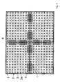
- Fig. 1 shows a plan view of the air distribution system with inventive air duct assemblies 30, joints and connectors 4.
- the view shows four air duct assemblies 30, which are connected via connecting elements 4 on the plate joint 1.
- the air guide assemblies 30 consist of a support surface or support plate 31 and conically tapered feet 3, 3a.
- the feet 3, 3a run on the bottom opposite conical.
- the connecting elements 4 are made of plastic plates with precisely fitting holes or recesses, which are pressed with a stamping device. For easier adaptation of the plates or support plates 31 to the spatial conditions, these can be modulated (stretched or compressed) at the existing perforations 2.
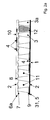
- Fig. 2a shows a section of the distribution system or through the air guide assembly 30 for floating floor coverings 6a.
- the section of the air distribution system shows the support plate 31 with the plate bottom 5, the feet 3 and the Abinneanpassungs owned 2.
- the feet 3, 3a run for better adhesion between the plate or support plate 31 and connector or connecting elements 4 at its respective bottom 9th conical to.
- the plate joints 1 are fixed together with connecting elements 4.
- the pressed-in air guide 12 gives the air-conveying cavity 11, the planned distributions of the supplied air.
- the cover 6 for floating floor coverings 6a preferably designed as a surface-finished floor covering is provided with Einrast Huawein 7, round recesses 8 in the lid for engaging the feet and at the top with knobs 10 for connectors. These nubs 10 also serve to bond adhesives.
- the cover is also provided with a height adjustment device 2 for better adaptation.
- Fig. 2b shows a section of the distribution system for bonded floor coverings.
- the distribution system corresponds 2a
- the cover has 6 b on the top over the entire surface distributed knobs 10 to increase the adhesion of a floor adhesive.
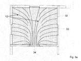
- Fig. 3a shows a plan view of the air distribution with symmetrical air supply with central air inlet without cover.
- An exemplary floor plan consisting of exterior walls and floor-to-ceiling windows on the left and top sides.
- the right and bottom sides feature interior walls with interior doors.
- the room is completely designed with connected support mats or support plates 30 and has circumferential air outlet strips in the wall, window and door area.
- the air distribution takes place via the air guide wedges 12 introduced according to the planning specification, which are laid between the feet 3, 3a.
- the air supply takes place at a central location, shown here by way of example in the door area, which is located in the center of the wall.
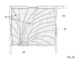
- Fig. 3b shows a plan view of the air distribution in asymmetric air supply.
- the spatial representation corresponds Fig. 3a However, the door area and thus the air supply is laterally offset.
- Fig. 4a schematically shows an air outlet strip, which is provided for a wall. Top view and section of the air outlet for the wall area.
- the two-piece air outlet strip is attached to the base body on the wall, preferably glued.
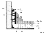
- the shape of the body consists of two air spoilers 13 with aerodynamic shape and recesses 16, which serve for mechanical attachment of the cover 14, in particular by means of snapping.
- the cover 14 of the air outlet strip with different designs and surfaces is positioned according to planning specification and locked via the spacers 15 on the body.
- the space between the base and cover is the air guide 11th
- Fig. 4b shows a section through the air outlet strip, as in Fig. 4a described in the application with flush mounting.
- the illustration shows the two-part air outlet in the application of flush mounting.
- the base body is mounted on the existing wall surface.
- the air duct assemblies of the air distribution system are brought flush to the air outlet.
- the air supplied to the bottom flows down into the air outlet and out at the top.
- the circumferential or circumferential strip ensures a uniform distribution of the air.
- flooring can be performed up to the lid of the air outlet and a skirting 26 are optional.
- the air outlet strip can be flush-mounted at the top.
- Fig. 4c shows the air outlet strip in section, as in Fig. 4a described in the application for surface mounting, preferably with grouting between the top of the body and the wall.
- flooring can be performed up to the lid of the air outlet and a skirting board 26 are optional.
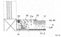
- Fig. 5a shows in section an air outlet strip for the floor ⁇ arranged here in the window area.
- the illustration shows the air outlet strip for use in front of windows, the air outlet strip being left in this illustration connects to the window sill.
- the air spoiler 25 serves for the aerodynamic air deflection of the supplied via the distribution system air 11 to the cover plate 18 with oblique air ducts.
- the cover is on two sides; one side contains a sound-decoupling, fixed support 19.
- the other side contains a sound-decoupled column foot 24 with screw 23 for height adjustment and a support guide 22 with internal thread and column head 21, which is threaded in the integrated guide rail 20 of the cover plate and can be adjusted in height , If necessary, the air outlet strip can be secured by screwing.
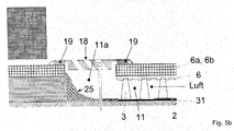
- Fig. 5b shows on average an air outlet strip for the floor - arranged here in the interior door area.
- the air outlet corresponds Fig. 5a , However, here is formed with double-sided fixed, sound-decoupling support 19 for the interior door area.
Landscapes
- Engineering & Computer Science (AREA)
- Architecture (AREA)
- General Engineering & Computer Science (AREA)
- Civil Engineering (AREA)
- Structural Engineering (AREA)
- Chemical & Material Sciences (AREA)
- Combustion & Propulsion (AREA)
- Mechanical Engineering (AREA)
- Duct Arrangements (AREA)
- Ventilation (AREA)
Applications Claiming Priority (1)
| Application Number | Priority Date | Filing Date | Title |
|---|---|---|---|
| DE102010048939A DE102010048939A1 (de) | 2010-10-19 | 2010-10-19 | Luftverteilsystem für Gebäude |
Publications (3)
| Publication Number | Publication Date |
|---|---|
| EP2444752A2 true EP2444752A2 (fr) | 2012-04-25 |
| EP2444752A3 EP2444752A3 (fr) | 2015-03-04 |
| EP2444752B1 EP2444752B1 (fr) | 2016-09-21 |
Family
ID=45524210
Family Applications (1)
| Application Number | Title | Priority Date | Filing Date |
|---|---|---|---|
| EP11008349.0A Not-in-force EP2444752B1 (fr) | 2010-10-19 | 2011-10-17 | Composant de guidage d'air pour un système de répartition d'air, système de répartition d'air pour bâtiments dotés de ce composant, procédé destiné à l'agencement du composant de guidage d'air ainsi que procédé de fonctionnement d'un système de répartition d'air |
Country Status (2)
| Country | Link |
|---|---|
| EP (1) | EP2444752B1 (fr) |
| DE (2) | DE102010048939A1 (fr) |
Cited By (4)
| Publication number | Priority date | Publication date | Assignee | Title |
|---|---|---|---|---|
| EP3115700A1 (fr) * | 2015-07-07 | 2017-01-11 | Rettig ICC B.V. | Convecteur souterrain |
| CN111867703A (zh) * | 2018-03-07 | 2020-10-30 | 产品无限公司 | 用于过滤装置的孔限定入口板 |
| SE545285C2 (en) * | 2022-02-23 | 2023-06-20 | Wahlberg Ventigolv AB | A diffuser component, a system and methods for floor displacement ventilation |
| US12201931B2 (en) | 2018-03-07 | 2025-01-21 | Products Unlimited, Inc. | Orifice-defining entry plate with support brace for filtration device |
Families Citing this family (2)
| Publication number | Priority date | Publication date | Assignee | Title |
|---|---|---|---|---|
| DE202019105353U1 (de) * | 2019-09-26 | 2021-01-04 | Ardex Anlagen Gmbh | Befestigungsprofil zur Befestigung einer Dekorleiste an einer Wand |
| FR3138837B1 (fr) * | 2022-08-11 | 2024-11-08 | Synapse Concept | Ensemble de diffusion d’air |
Family Cites Families (12)
| Publication number | Priority date | Publication date | Assignee | Title |
|---|---|---|---|---|
| DE2521374A1 (de) * | 1975-05-14 | 1976-12-02 | Rosemeier Kg | Bauelement fuer die draenage, bewaesserung, belueftung und beheizung von flaechen im erd-, grund-, wasser- und heizungsbau |
| DE3014390A1 (de) * | 1980-04-15 | 1981-10-22 | Polytherm Vertriebsgesellschaft haustechnischer Artikel mbH & Co KG, 4434 Ochtrup | Einrichtung fuer eine flaechenbeheizung |
| DE3217498C2 (de) * | 1982-05-10 | 1986-03-13 | geb. Weckauf Helga 4053 Jüchen Fermen | Verfahren zur Wärmerückgewinnung aus Verlusten von Fußbodenheizungen sowie Vorrichtung zur Durchführung dieses Verfahrens |
| DE3339713A1 (de) * | 1983-11-03 | 1985-05-15 | Ritter Heiztechnik GmbH, 4200 Oberhausen | Fussboden mit integrierter fussbodenheizung |
| SE446022B (sv) * | 1984-10-30 | 1986-08-04 | Peter Af Klinteberg | Ventilerat golv |
| DE3510475C1 (de) * | 1985-03-20 | 1986-10-02 | Donald Dipl.-Ing. 1000 Berlin Herbst | Vorrichtung zur Belüftung von Räumen |
| DE3625851C1 (de) * | 1986-07-31 | 1988-01-21 | Schmidt Reuter Ingenieurgmbh & | Fussboden-Flaechenheizung mit einer auf einem Unterboden verlegten Waermedaemmschicht |
| JP2602194B2 (ja) * | 1993-03-15 | 1997-04-23 | 株式会社インターセントラル | 冷暖房装置および該装置に用いる床パネル |
| DE10043288C2 (de) * | 2000-09-02 | 2002-11-21 | Schuetz Gmbh & Co Kgaa | Luftaußlaßkasten zum Einleiten von Warm- und/oder Kaltluft einer Raumheizung und/oder Raumkühlung in Gebäuderäume |
| DE10103001C1 (de) * | 2001-01-24 | 2002-10-24 | Schuetz Gmbh & Co Kgaa | Bodenelement zum Erstellen von Hohlraumböden für Heizrohre einer Raumheizung sowie für Heiz- und Kühlrohre einer kombinierten Raumheizung und Raumkühlung für Gebäude |
| JP3602101B2 (ja) * | 2002-02-01 | 2004-12-15 | 株式会社インターセントラル | 住宅用全空気方式床冷暖房システム |
| DE202005001965U1 (de) * | 2005-02-08 | 2006-06-14 | Gutjahr, Walter | Drainage-Bahn- oder Plattenmaterial zur entwässernden und/oder entlüftenden Verlegung von Plattenbelägen im Dünnbett |
-
2010
- 2010-10-19 DE DE102010048939A patent/DE102010048939A1/de not_active Withdrawn
-
2011
- 2011-10-17 DE DE102011116219A patent/DE102011116219A1/de not_active Withdrawn
- 2011-10-17 EP EP11008349.0A patent/EP2444752B1/fr not_active Not-in-force
Non-Patent Citations (1)
| Title |
|---|
| None |
Cited By (6)
| Publication number | Priority date | Publication date | Assignee | Title |
|---|---|---|---|---|
| EP3115700A1 (fr) * | 2015-07-07 | 2017-01-11 | Rettig ICC B.V. | Convecteur souterrain |
| CN111867703A (zh) * | 2018-03-07 | 2020-10-30 | 产品无限公司 | 用于过滤装置的孔限定入口板 |
| US11986761B2 (en) | 2018-03-07 | 2024-05-21 | Products Unlimited, Inc. | Orifice-defining entry plate for filtration device |
| US12201931B2 (en) | 2018-03-07 | 2025-01-21 | Products Unlimited, Inc. | Orifice-defining entry plate with support brace for filtration device |
| SE545285C2 (en) * | 2022-02-23 | 2023-06-20 | Wahlberg Ventigolv AB | A diffuser component, a system and methods for floor displacement ventilation |
| SE2250242A1 (en) * | 2022-02-23 | 2023-06-20 | Wahlberg Ventigolv AB | A diffuser component, a system and methods for floor displacement ventilation |
Also Published As
| Publication number | Publication date |
|---|---|
| DE102011116219A1 (de) | 2012-05-03 |
| DE102010048939A1 (de) | 2012-04-19 |
| EP2444752A3 (fr) | 2015-03-04 |
| EP2444752B1 (fr) | 2016-09-21 |
Similar Documents
| Publication | Publication Date | Title |
|---|---|---|
| EP2444752B1 (fr) | Composant de guidage d'air pour un système de répartition d'air, système de répartition d'air pour bâtiments dotés de ce composant, procédé destiné à l'agencement du composant de guidage d'air ainsi que procédé de fonctionnement d'un système de répartition d'air | |
| DE4326495C2 (de) | Fußbodenheizung | |
| EP2887839A1 (fr) | Appareil de réfrigération | |
| EP0074490B1 (fr) | Sol avec chauffage intégré par eau chaude | |
| DE202016002037U1 (de) | System zur Flächentemperierung in Bereichen mit durchlaufenden Zuleitungen | |
| DE102008024634A1 (de) | Wohnmobil oder Wohnwagen mit Warmluft-Thermoboden | |
| DE10103001C1 (de) | Bodenelement zum Erstellen von Hohlraumböden für Heizrohre einer Raumheizung sowie für Heiz- und Kühlrohre einer kombinierten Raumheizung und Raumkühlung für Gebäude | |
| EP2210992B1 (fr) | Plaque semi-finie thermoactive dotée d'un absorbeur acoustique | |
| EP3285017B1 (fr) | Panneau de plafond radiant chauffant et rafraîchissant comprenant au moins un ventilateur | |
| DE202017101128U1 (de) | Flächentemperiersystem | |
| DE3217498C2 (de) | Verfahren zur Wärmerückgewinnung aus Verlusten von Fußbodenheizungen sowie Vorrichtung zur Durchführung dieses Verfahrens | |
| DE102008059459A1 (de) | Herstellverfahren für einen Fußbodenaufbau in einem Gebäuderaum, sowie Fußbodenelemente und Sockelleistenbausatz zur Durchführung des Verfahrens | |
| DE202007017185U1 (de) | Wärmeverbundsystem sowie ein Flächenheizungs/-kühlungs-Baukastensystem mit einem derartigen Wärmeverbundsystem | |
| EP3361164B1 (fr) | Panneau de plancher, en particulier destiné à la construction d'un plancher au sol ventilé pouvant être tempéré | |
| DE102011002605B4 (de) | Dezentrale Raumlüftungsvorrichtung mit Wärmerückgewinnung | |
| CH701880A2 (de) | Luftführungssystem zur Belüftung von Räumen eines Gebäudes. | |
| DE102017221725B4 (de) | Fluidkanal | |
| DE3625851C1 (de) | Fussboden-Flaechenheizung mit einer auf einem Unterboden verlegten Waermedaemmschicht | |
| DE19848003A1 (de) | Betondecken- und Wandelement | |
| DE3941618A1 (de) | Vorrichtung zum kuehlen oder heizen eines raumes | |
| EP0098464A1 (fr) | Diffuseur d'air pour ventilation d'enceintes | |
| DE8400402U1 (de) | Sandwich-Wärmetauscher | |
| DE3329551C1 (de) | Fußbodenheizeinrichtung | |
| WO2010034498A2 (fr) | Dispositif de climatisation d'un local | |
| EP3106766A1 (fr) | Dispositif de climatisation sous plancher |
Legal Events
| Date | Code | Title | Description |
|---|---|---|---|
| AK | Designated contracting states |
Kind code of ref document: A2 Designated state(s): AL AT BE BG CH CY CZ DE DK EE ES FI FR GB GR HR HU IE IS IT LI LT LU LV MC MK MT NL NO PL PT RO RS SE SI SK SM TR |
|
| AX | Request for extension of the european patent |
Extension state: BA ME |
|
| PUAI | Public reference made under article 153(3) epc to a published international application that has entered the european phase |
Free format text: ORIGINAL CODE: 0009012 |
|
| PUAL | Search report despatched |
Free format text: ORIGINAL CODE: 0009013 |
|
| AK | Designated contracting states |
Kind code of ref document: A3 Designated state(s): AL AT BE BG CH CY CZ DE DK EE ES FI FR GB GR HR HU IE IS IT LI LT LU LV MC MK MT NL NO PL PT RO RS SE SI SK SM TR |
|
| AX | Request for extension of the european patent |
Extension state: BA ME |
|
| RIC1 | Information provided on ipc code assigned before grant |
Ipc: F24F 13/06 20060101ALI20150129BHEP Ipc: F24F 7/04 20060101AFI20150129BHEP Ipc: E04F 19/06 20060101ALI20150129BHEP Ipc: E04F 15/024 20060101ALI20150129BHEP Ipc: F24F 13/22 20060101ALI20150129BHEP Ipc: E04F 19/04 20060101ALI20150129BHEP Ipc: E04B 5/48 20060101ALI20150129BHEP |
|
| 17P | Request for examination filed |
Effective date: 20150818 |
|
| RBV | Designated contracting states (corrected) |
Designated state(s): AL AT BE BG CH CY CZ DE DK EE ES FI FR GB GR HR HU IE IS IT LI LT LU LV MC MK MT NL NO PL PT RO RS SE SI SK SM TR |
|
| GRAP | Despatch of communication of intention to grant a patent |
Free format text: ORIGINAL CODE: EPIDOSNIGR1 |
|
| RIC1 | Information provided on ipc code assigned before grant |
Ipc: E04F 19/04 20060101ALI20160304BHEP Ipc: E04F 15/024 20060101ALI20160304BHEP Ipc: E04B 5/48 20060101ALI20160304BHEP Ipc: F24F 13/06 20060101ALI20160304BHEP Ipc: F24F 13/22 20060101ALI20160304BHEP Ipc: F24F 7/04 20060101AFI20160304BHEP Ipc: E04F 19/06 20060101ALI20160304BHEP |
|
| INTG | Intention to grant announced |
Effective date: 20160405 |
|
| GRAS | Grant fee paid |
Free format text: ORIGINAL CODE: EPIDOSNIGR3 |
|
| GRAA | (expected) grant |
Free format text: ORIGINAL CODE: 0009210 |
|
| AK | Designated contracting states |
Kind code of ref document: B1 Designated state(s): AL AT BE BG CH CY CZ DE DK EE ES FI FR GB GR HR HU IE IS IT LI LT LU LV MC MK MT NL NO PL PT RO RS SE SI SK SM TR |
|
| REG | Reference to a national code |
Ref country code: GB Ref legal event code: FG4D Free format text: NOT ENGLISH |
|
| REG | Reference to a national code |
Ref country code: CH Ref legal event code: EP |
|
| REG | Reference to a national code |
Ref country code: AT Ref legal event code: REF Ref document number: 831373 Country of ref document: AT Kind code of ref document: T Effective date: 20161015 |
|
| REG | Reference to a national code |
Ref country code: IE Ref legal event code: FG4D Free format text: LANGUAGE OF EP DOCUMENT: GERMAN |
|
| REG | Reference to a national code |
Ref country code: FR Ref legal event code: PLFP Year of fee payment: 6 |
|
| REG | Reference to a national code |
Ref country code: DE Ref legal event code: R096 Ref document number: 502011010708 Country of ref document: DE |
|
| REG | Reference to a national code |
Ref country code: LT Ref legal event code: MG4D Ref country code: NL Ref legal event code: MP Effective date: 20160921 |
|
| PG25 | Lapsed in a contracting state [announced via postgrant information from national office to epo] |
Ref country code: FI Free format text: LAPSE BECAUSE OF FAILURE TO SUBMIT A TRANSLATION OF THE DESCRIPTION OR TO PAY THE FEE WITHIN THE PRESCRIBED TIME-LIMIT Effective date: 20160921 Ref country code: NO Free format text: LAPSE BECAUSE OF FAILURE TO SUBMIT A TRANSLATION OF THE DESCRIPTION OR TO PAY THE FEE WITHIN THE PRESCRIBED TIME-LIMIT Effective date: 20161221 Ref country code: RS Free format text: LAPSE BECAUSE OF FAILURE TO SUBMIT A TRANSLATION OF THE DESCRIPTION OR TO PAY THE FEE WITHIN THE PRESCRIBED TIME-LIMIT Effective date: 20160921 Ref country code: LT Free format text: LAPSE BECAUSE OF FAILURE TO SUBMIT A TRANSLATION OF THE DESCRIPTION OR TO PAY THE FEE WITHIN THE PRESCRIBED TIME-LIMIT Effective date: 20160921 |
|
| PGFP | Annual fee paid to national office [announced via postgrant information from national office to epo] |
Ref country code: DE Payment date: 20161109 Year of fee payment: 6 Ref country code: GB Payment date: 20161027 Year of fee payment: 6 Ref country code: CH Payment date: 20161107 Year of fee payment: 6 Ref country code: FR Payment date: 20161027 Year of fee payment: 6 |
|
| PG25 | Lapsed in a contracting state [announced via postgrant information from national office to epo] |
Ref country code: NL Free format text: LAPSE BECAUSE OF FAILURE TO SUBMIT A TRANSLATION OF THE DESCRIPTION OR TO PAY THE FEE WITHIN THE PRESCRIBED TIME-LIMIT Effective date: 20160921 Ref country code: SE Free format text: LAPSE BECAUSE OF FAILURE TO SUBMIT A TRANSLATION OF THE DESCRIPTION OR TO PAY THE FEE WITHIN THE PRESCRIBED TIME-LIMIT Effective date: 20160921 Ref country code: GR Free format text: LAPSE BECAUSE OF FAILURE TO SUBMIT A TRANSLATION OF THE DESCRIPTION OR TO PAY THE FEE WITHIN THE PRESCRIBED TIME-LIMIT Effective date: 20161222 Ref country code: LV Free format text: LAPSE BECAUSE OF FAILURE TO SUBMIT A TRANSLATION OF THE DESCRIPTION OR TO PAY THE FEE WITHIN THE PRESCRIBED TIME-LIMIT Effective date: 20160921 Ref country code: BE Free format text: LAPSE BECAUSE OF NON-PAYMENT OF DUE FEES Effective date: 20161031 |
|
| PGFP | Annual fee paid to national office [announced via postgrant information from national office to epo] |
Ref country code: AT Payment date: 20161109 Year of fee payment: 6 |
|
| PG25 | Lapsed in a contracting state [announced via postgrant information from national office to epo] |
Ref country code: EE Free format text: LAPSE BECAUSE OF FAILURE TO SUBMIT A TRANSLATION OF THE DESCRIPTION OR TO PAY THE FEE WITHIN THE PRESCRIBED TIME-LIMIT Effective date: 20160921 Ref country code: RO Free format text: LAPSE BECAUSE OF FAILURE TO SUBMIT A TRANSLATION OF THE DESCRIPTION OR TO PAY THE FEE WITHIN THE PRESCRIBED TIME-LIMIT Effective date: 20160921 |
|
| PG25 | Lapsed in a contracting state [announced via postgrant information from national office to epo] |
Ref country code: IS Free format text: LAPSE BECAUSE OF FAILURE TO SUBMIT A TRANSLATION OF THE DESCRIPTION OR TO PAY THE FEE WITHIN THE PRESCRIBED TIME-LIMIT Effective date: 20170121 Ref country code: ES Free format text: LAPSE BECAUSE OF FAILURE TO SUBMIT A TRANSLATION OF THE DESCRIPTION OR TO PAY THE FEE WITHIN THE PRESCRIBED TIME-LIMIT Effective date: 20160921 Ref country code: PL Free format text: LAPSE BECAUSE OF FAILURE TO SUBMIT A TRANSLATION OF THE DESCRIPTION OR TO PAY THE FEE WITHIN THE PRESCRIBED TIME-LIMIT Effective date: 20160921 Ref country code: BG Free format text: LAPSE BECAUSE OF FAILURE TO SUBMIT A TRANSLATION OF THE DESCRIPTION OR TO PAY THE FEE WITHIN THE PRESCRIBED TIME-LIMIT Effective date: 20161221 Ref country code: PT Free format text: LAPSE BECAUSE OF FAILURE TO SUBMIT A TRANSLATION OF THE DESCRIPTION OR TO PAY THE FEE WITHIN THE PRESCRIBED TIME-LIMIT Effective date: 20170123 Ref country code: CZ Free format text: LAPSE BECAUSE OF FAILURE TO SUBMIT A TRANSLATION OF THE DESCRIPTION OR TO PAY THE FEE WITHIN THE PRESCRIBED TIME-LIMIT Effective date: 20160921 Ref country code: SK Free format text: LAPSE BECAUSE OF FAILURE TO SUBMIT A TRANSLATION OF THE DESCRIPTION OR TO PAY THE FEE WITHIN THE PRESCRIBED TIME-LIMIT Effective date: 20160921 Ref country code: SM Free format text: LAPSE BECAUSE OF FAILURE TO SUBMIT A TRANSLATION OF THE DESCRIPTION OR TO PAY THE FEE WITHIN THE PRESCRIBED TIME-LIMIT Effective date: 20160921 |
|
| REG | Reference to a national code |
Ref country code: DE Ref legal event code: R097 Ref document number: 502011010708 Country of ref document: DE |
|
| PG25 | Lapsed in a contracting state [announced via postgrant information from national office to epo] |
Ref country code: IT Free format text: LAPSE BECAUSE OF FAILURE TO SUBMIT A TRANSLATION OF THE DESCRIPTION OR TO PAY THE FEE WITHIN THE PRESCRIBED TIME-LIMIT Effective date: 20160921 |
|
| REG | Reference to a national code |
Ref country code: IE Ref legal event code: MM4A |
|
| PLBE | No opposition filed within time limit |
Free format text: ORIGINAL CODE: 0009261 |
|
| STAA | Information on the status of an ep patent application or granted ep patent |
Free format text: STATUS: NO OPPOSITION FILED WITHIN TIME LIMIT |
|
| PG25 | Lapsed in a contracting state [announced via postgrant information from national office to epo] |
Ref country code: DK Free format text: LAPSE BECAUSE OF FAILURE TO SUBMIT A TRANSLATION OF THE DESCRIPTION OR TO PAY THE FEE WITHIN THE PRESCRIBED TIME-LIMIT Effective date: 20160921 |
|
| 26N | No opposition filed |
Effective date: 20170622 |
|
| PG25 | Lapsed in a contracting state [announced via postgrant information from national office to epo] |
Ref country code: LU Free format text: LAPSE BECAUSE OF NON-PAYMENT OF DUE FEES Effective date: 20161017 |
|
| PG25 | Lapsed in a contracting state [announced via postgrant information from national office to epo] |
Ref country code: IE Free format text: LAPSE BECAUSE OF NON-PAYMENT OF DUE FEES Effective date: 20161017 Ref country code: SI Free format text: LAPSE BECAUSE OF FAILURE TO SUBMIT A TRANSLATION OF THE DESCRIPTION OR TO PAY THE FEE WITHIN THE PRESCRIBED TIME-LIMIT Effective date: 20160921 |
|
| REG | Reference to a national code |
Ref country code: BE Ref legal event code: MM Effective date: 20161031 |
|
| REG | Reference to a national code |
Ref country code: DE Ref legal event code: R119 Ref document number: 502011010708 Country of ref document: DE |
|
| PG25 | Lapsed in a contracting state [announced via postgrant information from national office to epo] |
Ref country code: CY Free format text: LAPSE BECAUSE OF FAILURE TO SUBMIT A TRANSLATION OF THE DESCRIPTION OR TO PAY THE FEE WITHIN THE PRESCRIBED TIME-LIMIT Effective date: 20160921 Ref country code: HU Free format text: LAPSE BECAUSE OF FAILURE TO SUBMIT A TRANSLATION OF THE DESCRIPTION OR TO PAY THE FEE WITHIN THE PRESCRIBED TIME-LIMIT; INVALID AB INITIO Effective date: 20111017 |
|
| REG | Reference to a national code |
Ref country code: CH Ref legal event code: PL |
|
| REG | Reference to a national code |
Ref country code: AT Ref legal event code: MM01 Ref document number: 831373 Country of ref document: AT Kind code of ref document: T Effective date: 20171017 |
|
| GBPC | Gb: european patent ceased through non-payment of renewal fee |
Effective date: 20171017 |
|
| PG25 | Lapsed in a contracting state [announced via postgrant information from national office to epo] |
Ref country code: MK Free format text: LAPSE BECAUSE OF FAILURE TO SUBMIT A TRANSLATION OF THE DESCRIPTION OR TO PAY THE FEE WITHIN THE PRESCRIBED TIME-LIMIT Effective date: 20160921 Ref country code: MC Free format text: LAPSE BECAUSE OF FAILURE TO SUBMIT A TRANSLATION OF THE DESCRIPTION OR TO PAY THE FEE WITHIN THE PRESCRIBED TIME-LIMIT Effective date: 20160921 Ref country code: MT Free format text: LAPSE BECAUSE OF FAILURE TO SUBMIT A TRANSLATION OF THE DESCRIPTION OR TO PAY THE FEE WITHIN THE PRESCRIBED TIME-LIMIT Effective date: 20160921 Ref country code: TR Free format text: LAPSE BECAUSE OF FAILURE TO SUBMIT A TRANSLATION OF THE DESCRIPTION OR TO PAY THE FEE WITHIN THE PRESCRIBED TIME-LIMIT Effective date: 20160921 Ref country code: HR Free format text: LAPSE BECAUSE OF FAILURE TO SUBMIT A TRANSLATION OF THE DESCRIPTION OR TO PAY THE FEE WITHIN THE PRESCRIBED TIME-LIMIT Effective date: 20160921 |
|
| REG | Reference to a national code |
Ref country code: FR Ref legal event code: ST Effective date: 20180629 |
|
| PG25 | Lapsed in a contracting state [announced via postgrant information from national office to epo] |
Ref country code: GB Free format text: LAPSE BECAUSE OF NON-PAYMENT OF DUE FEES Effective date: 20171017 Ref country code: DE Free format text: LAPSE BECAUSE OF NON-PAYMENT OF DUE FEES Effective date: 20180501 Ref country code: LI Free format text: LAPSE BECAUSE OF NON-PAYMENT OF DUE FEES Effective date: 20171031 Ref country code: CH Free format text: LAPSE BECAUSE OF NON-PAYMENT OF DUE FEES Effective date: 20171031 |
|
| PG25 | Lapsed in a contracting state [announced via postgrant information from national office to epo] |
Ref country code: FR Free format text: LAPSE BECAUSE OF NON-PAYMENT OF DUE FEES Effective date: 20171031 Ref country code: AT Free format text: LAPSE BECAUSE OF NON-PAYMENT OF DUE FEES Effective date: 20171017 |
|
| PG25 | Lapsed in a contracting state [announced via postgrant information from national office to epo] |
Ref country code: AL Free format text: LAPSE BECAUSE OF FAILURE TO SUBMIT A TRANSLATION OF THE DESCRIPTION OR TO PAY THE FEE WITHIN THE PRESCRIBED TIME-LIMIT Effective date: 20160921 |