EP2444945A1 - Warnsystem und -verfahren für schwerhörige oder taube Personen - Google Patents
Warnsystem und -verfahren für schwerhörige oder taube Personen Download PDFInfo
- Publication number
- EP2444945A1 EP2444945A1 EP11005141A EP11005141A EP2444945A1 EP 2444945 A1 EP2444945 A1 EP 2444945A1 EP 11005141 A EP11005141 A EP 11005141A EP 11005141 A EP11005141 A EP 11005141A EP 2444945 A1 EP2444945 A1 EP 2444945A1
- Authority
- EP
- European Patent Office
- Prior art keywords
- alerting
- sound
- electric
- producing means
- alerting system
- Prior art date
- Legal status (The legal status is an assumption and is not a legal conclusion. Google has not performed a legal analysis and makes no representation as to the accuracy of the status listed.)
- Withdrawn
Links
Images


Classifications
-
- G—PHYSICS
- G08—SIGNALLING
- G08B—SIGNALLING SYSTEMS, e.g. PERSONAL CALLING SYSTEMS; ORDER TELEGRAPHS; ALARM SYSTEMS
- G08B6/00—Tactile signalling systems, e.g. tactile personal calling systems
-
- G—PHYSICS
- G08—SIGNALLING
- G08B—SIGNALLING SYSTEMS, e.g. PERSONAL CALLING SYSTEMS; ORDER TELEGRAPHS; ALARM SYSTEMS
- G08B25/00—Alarm systems in which the location of the alarm condition is signalled to a central station, e.g. fire or police telegraphic systems
- G08B25/009—Signalling of the alarm condition to a substation whose identity is signalled to a central station, e.g. relaying alarm signals in order to extend communication range
-
- H—ELECTRICITY
- H04—ELECTRIC COMMUNICATION TECHNIQUE
- H04R—LOUDSPEAKERS, MICROPHONES, GRAMOPHONE PICK-UPS OR LIKE ACOUSTIC ELECTROMECHANICAL TRANSDUCERS; ELECTRIC HEARING AIDS; PUBLIC ADDRESS SYSTEMS
- H04R5/00—Stereophonic arrangements
- H04R5/02—Spatial or constructional arrangements of loudspeakers
- H04R5/023—Spatial or constructional arrangements of loudspeakers in a chair, pillow
-
- H—ELECTRICITY
- H04—ELECTRIC COMMUNICATION TECHNIQUE
- H04R—LOUDSPEAKERS, MICROPHONES, GRAMOPHONE PICK-UPS OR LIKE ACOUSTIC ELECTROMECHANICAL TRANSDUCERS; ELECTRIC HEARING AIDS; PUBLIC ADDRESS SYSTEMS
- H04R2420/00—Details of connection covered by H04R, not provided for in its groups
- H04R2420/07—Applications of wireless loudspeakers or wireless microphones
Definitions
- the present invention relates to an alerting system and method for hard of hearing or deaf people.
- bed or pillow shakers have become available for people with hearing impairment and may be used with an alarm clock or for emergency notification during sleep, see for example Canadian patent specification CA 1 123 945 .
- bed or pillow shakers are only 80% to 83% effective to wake up hard of hearing and deaf people below the age of 60 years. The effectiveness is even lower for people with an age over 60 years.
- JP 2008 194148 suggests the use a cellular phone in a pillow as an alerting device.
- the cellular phone produces electro-smog close to the head of a sleeping person during the whole night.
- the battery of the cell phone runs low in the night and the cell phone automatically switches off, the alarm cannot be activated.
- mobile phones are complicated devices and it can be difficult for inexperienced users and elderly people to find the correct alarm settings.
- An alarm clock system comprising a base station with a clock for a music player, a radio and main loud speakers, and a bed shaker connected to the base station via a cable.
- the bed shaker is adapted to vibrate and comprises a separate loudspeaker for reproducing sound on the basis of an audio signal from the base station.
- This versatile alarm clock system provides numerous settings selectable by the user.
- a wake mode can be chosen among a plurality of pre-defined wake modes some of which involve the bed shaker and some of which do not. If "buzzer" is selected in the wake mode, the buzzing sound can be selected among a plurality of pre-defined buzzing sounds, some of which may be easily overheard by hard of hearing people.
- a switch is provided for selecting between the base speakers only, the shaker speaker only, or both kinds of speakers.
- the bed shaker comprises a switch for selecting different volume levels of the shaker speaker. For inexperienced users and elderly people the numerous features may be confusing and wrong settings can easily occur such that the bed shaker is set to a mode where it cannot be heard, or can easily be overheard, by a hard of hearing person, or that the bed-shaker is even deactivated.
- the alerting sound is completely produced in the sound producing means, i.e. in the alerting device.
- the activating device provides to the alerting device exclusively AC or DC power supply through the power cable. In simple words, the activating device turns power on for the alerting device in the case of an alarm, and the alerting device when being powered does all the rest by vibrating, and generating and outputs the alarm sound.
- the inventive configuration allows easy upgrading of existing alerting systems by exchanging the conventional alerting device with an inventive alerting device.
- a modification of the activating device by generating an audio signal and sending the same to the alerting device is not required. Furthermore, and very important, the alerting sound does not depend on any settings in the activating device, apart from an eventual alarm setting, which reduces the probability of wrong settings to an absolute minimum. Consequently, the risk that the bed shaker is set to a mode where it cannot be heard, or can easily be overheard, by a hard of hearing person, or that the bed-shaker is even deactivated, is reduced to a minimum.
- Supply voltage according to the invention comprises a DC voltage or an AC voltage, where AC voltage in this application means a voltage with a constant periodic waveform.
- a constant periodic waveform gives a constant curve in an oscillogram.
- This definition comprises for example a preferred sinusoidal waveform, but also a rectangular, square or triangular waveform. This definition does not, however, comprise permanently varying waveforms which are occurring in transmitting sound information like music or speech, or in communication.
- an alerting sound according to the invention in addition to the vibrations, can significantly improve the effectiveness of the alerting system for deaf, profound deaf or hard of hearing people, because even deaf people in some cases hear sound at least to a certain degree.
- the alerting sound is produced in the alerting device which also produces the vibrations.
- the volume of the alerting sound is adjusted such that it is perceptible by an average hard of hearing or deaf person when the alerting device is placed in a tactile relationship to the person, for example in, under or on a pillow or mattress.
- Externally powered means that the alerting device is powered by an external power source, in particular a power source arranged in the activating device like a battery, a transformer, a rectifier and the like, and can preferably mean that the alerting device does not comprise an own internal power source, such as a battery.
- an external power source in particular a power source arranged in the activating device like a battery, a transformer, a rectifier and the like, and can preferably mean that the alerting device does not comprise an own internal power source, such as a battery.
- the activating device and the alerting device are separate devices which are connected by a power cable.
- the activating device may therefore be placed remote from the alerting device, for example on a bed table.
- the activating device may be constantly powered, where electro-smog is unproblematic if the activating device is placed remote from the alerting device which is placed close to the body of the user.
- the alarm signal may be internally produced within the activating device by an integrated alarm generator, for example a timer if the activating device is an alarm clock.
- the activating device may have access to a wired or wireless communication link to one or more external alarm signal emitter, like smoke detector, baby cry emitter, door bell emitter, telephone call transmitter, message transmitter, alarm clock, contact mat, door switch, and/or any suited item of a personal alarm system for hard of hearing persons.
- the activating device expediently comprises a receiver for receiving the alarm signal from the external alarm signal emitter via the communication link.
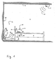
- Fig. 1 shows a bed room 1 of a hard of hearing or deaf person with a bed 3 and a pillow 5.
- An external alarm signal emitter 7, here a smoke detector is provided, here mounted at the ceiling 9 of the bed room 1.
- an alerting system 11 comprising an activating device 13 and an alerting device 15, here a bed shaker or pillow shaker, is provided, here installed at the bed 3 in order to alert a sleeping hard of hearing or deaf person, for example in case of fire.
- the externally powered alerting device 15 is located for example under or in the pillow 5, or alternatively under or in the mattress, of the bed 3.
- the alerting device 15 is located in tactile relationship, i.e. close to the body of a user, such that vibrations of the alerting device 15 can be perceived by the user.
- the activating device 13 is adapted to receive an alarm signal 27 from the alarm signal emitter 7.
- the alarm signal 27 may be emitted as a radio frequency signal.
- the alarm signal 27 could also be any other wireless signal.
- the activating device 13 comprises an appropriate receiving means 10 for receiving such a signal.
- the activating device 13 may be equipped with an R.F. antenna 26 and an R.F. receiver circuit.
- the activating device 13 could be wired to the alarm signal emitter 7.
- the activating device 13 preferably comprises an internal DC or AC power source 23 in particular for the alerting device 15.
- This may for example be a voltage transformer, a rectifier, a battery like a rechargeable battery, or any other suited electric power source.
- the activating device 13 is connectable to mains supply and, therefore, expediently includes a plug 17 which is pluggable into a mains power socket 19 in a wall 21 of the bed room 1.
- the activating device 13 preferably comprises a power cable not shown in Fig. 1 such that the activating device 13 can be placed remotely from the mains socket 19, for example on a bed table.
- the activating device 13 in the present example includes a voltage transformer 23 for transforming AC mains voltage into any desired AC and/or DC voltage for internal powering and powering of the alerting device 15.
- a DC voltage may be preferred in view of upgradeability and simple set-up, since preferably a DC motor is used as a vibrating element 43.
- the voltage applied to the power cable 37 should be below 20 V in view of user safety.
- the activating device 13 is connected to the alerting device 15 via a power cable 37 through which the activating device 13 is able to power the alerting device 15.
- This is controlled by a control means 25 provided in the activating device 13.
- the control means 25 may for example be an electronic processing means, for example a digital signal processor.
- the control means 25 is adapted, in particular programmed, to control providing of a supply current to the alerting device 15 through the power cable 37 upon reception of the alarm signal 27.
- the control means 25 may connect the power source 23 to the power cable 37 by controlling suited switching means.
- the control means 25 may control connecting an external power source, for example mains supply, to the power cable 37.
- the power cable 37 may be fixed to the alerting device 15, and may be detachable from the activating device 13, for example by means of a plug/socket connection 40 as indicated in Figs. 5 to 9 .
- the alerting device 15 comprises an electric vibrating element 43, for example an electric motor with an unbalanced mass.
- the supply voltage is applied to the vibrating element 43 which produces vibrations perceptible by a hard of hearing or deaf person.
- the alerting device 15 comprises a separate sound producing means 45 adapted to produce, upon being supplied with a supply current through the supply cable 37, a pre-defined alerting sound 35 hearable by a hard of hearing or deaf person.
- a pre-defined alerting sound 35 hearable by a hard of hearing or deaf person.
- the volume and the sound pattern of the alerting sound 35 cannot be changed nor affected by the user, at least not in normal operation, nor can the sound producing means be switched off. In this manner it is guaranteed that a perdefined alerting sound with a sufficient volume and optimum sound pattern for a hard of hearing user is emitted if only the alerting device 15 is connected to the activating device 13.
- the alerting sound may be most effective if it comprises an essentially mono-frequent tone with a peak frequency preferably in the range of 400 Hz to 800 Hz, more preferably 400 Hz to 600 Hz, even more preferably 450 Hz to 550 Hz.
- the alerting sound has an intermittent time pattern being on and off in succession, in particular a square wave time pattern.
- the tone is on and off for a predetermined number of times in succession, preferably three to seven times each, more preferably three to five times each.
- each of these ON periods last no more than 2 s, preferably no more than 1 s, for example for about 0.5 s. The same applies to the OFF periods in between the ON periods.
- a pause of at least 5 s for example also in the range of 10 to 30 seconds, preferably 10 to 15 seconds, follows.
- alerting sound patterns and pauses may follow in an alternating manner.
- the ON and OFF periods of the alerting sound may be produced by intermittently switching the power supply through the power cable 37 on and off.
- the power supply through the power cable 37 is constant over an alarm, and the intermittent ON-OFF pattern of the alerting sound is produced in the sound producing means 45.
- the alarm signal emitter 7 detects smoke and emits an alarm signal 27.
- the alarm signal 27 is received by the activating device 13.
- the control means 25 activates for example the voltage transformer 23 by switching on an electric circuit of a primary winding of the voltage transformer 23.
- the secondary winding of the voltage transformer 23 for example is electrically coupled to the alerting device 15 via the cable 37. In this manner, supply current is provided through the cable 37 for powering the alerting device 15.
- the alerting device 15 produces both vibrations and an alerting sound 35 hearable or perceptible by a hard of hearing or deaf person. Such person sleeping in the bed 3 will wake up upon hearing and/or feeling one or both of the vibrations and/or the sound 35.
- Fig. 2 shows a more abstract scheme of an alerting system 11 according to the invention.
- An alarm signal emitter 7 of any kind such as a baby cry emitter, a door bell transmitter, a telephone call transmitter, a message transmitter, a fire alarm emitter, or an alarm clock, is connected via a signal link 39 to the alerting system 11.
- the signal link 39 is preferably wireless, but may also be wired.
- the activating device 13 may be externally powered like in Figure 1 , and may for example be a charging station for a pager, a flash receiver, or any other suitable device of a personal alarm system for deaf or hard of hearing people.
- the activating device 13 may be internally powered, in particular by a battery like a rechargeable battery, and may for example be a portable wireless receiver device, or any other suitable internally powered device of a personal alarm system for deaf or hard of hearing people.
- the alerting system 11 shown in Fig. 3 differs from the one shown in Fig. 2 in that the alarm signal is produced within the activating device 13 in an internal alarm signal generator 8, for example a timer 8 in an alarm clock 13.
- an alarm clock is integrated in the activating device 13, or an alarm clock is designed as an activating device 13 having for example a power output terminal for the alerting device 15.
- an activating device 13, in particular an alarm clock, with an alarm signal generator or timer 8 also comprises a receiver 10 for receiving an alarm signal from an external alarm signal emitter 7, thus forming an alarm clock receiver device 13.
- the control circuit 25 will power the alerting device 15 both upon receipt of an unscheduled alarm signal from the alarm signal emitter 7 and independently upon receipt of a scheduled internal alarm.signal from the timer 8.
- FIGs 5 to 9 show different practical embodiments of an alerting system 11. It should be understood that any of the schematic embodiments shown in Figs. 2 to 4 may be combined with any of the practical embodiments shown in Figs 5 to 9 in order to realize the invention.
- the vibrating element 43 is an electric motor provided with an unbalanced mass. This may be a DC motor or an AC motor, supplied via two electric power lines 38 provided in the power cable 37.
- the sound producing means is a buzzer 45A.
- a buzzer 45A is an electric device which combines all components required to produce an alerting sound 35 from an input supply voltage into a single device preferably having a single casing. In contrast to a dynamic loudspeaker device it does not comprise an oscillating coil.
- the buzzer 45A may in particular be a piezo buzzer or a magnetic buzzer.
- a piezo buzzer comprises a piezo-electric element.
- a magnetic buzzer comprises a fixed permanent magnet and a fixed electro magnet which generates a magnetic flux proportional to the desired sound amplitude from an input acoustic signal. The magnetic flux exerts a force to a membrane which moves and thus emits sound.
- the sound producing means 45B comprises a dynamic loudspeaker 48 with an oscillating coil and a membrane, and an audio signal generator 47 which generates an electric audio signal.
- the electric audio signal comprises the sound information and is input to the dynamic loudspeaker 48 in order to produce the sound waves, or sound, 35.
- the audio signal generator 47 may comprise a memory for storing pre-recorded sound.
- the sound producing means 45C comprises a buzzing element 46 and an audio signal generator, or driving means, 47 which generates an electric driving signal for driving the buzzing element 46.
- the electric driving signal comprises the sound information and is input to the buzzing element 46 in order to produce the sound waves, or sound, 35.
- the buzzing element 46 is a simple loudspeaker not having a moving coil, and may in particular be a piezo-electric loudspeaker or a magnetic loudspeaker.
- a piezo-electric loudspeaker comprises a piezo-electric element.
- a magnetic loudspeaker comprises a fixed permanent magnet and a fixed electro magnet which generates a magnetic flux proportional to the sound amplitude from an input acoustic signal. The magnetic flux exerts a force to a membrane which moves and thus emits sound.
- the buzzer 45A shown in Fig. 5 may be regarded as an integrated element combining a buzzing element 46 and the driving means, or audio signal generator, 47 of Fig. 7 into a single device advantageously having a single casing.
- the sound producing means 45A-45C requires only two voltage supply lines 38 providing a usual DC, or sinusoidal AC, supply voltage. This allows updating of conventional alerting systems 11 by replacing a conventional bed-shaker having a vibrating element 43, only, with an inventive bed-shaker 15 having a vibrating element 43 and a sound generating element 45, without having to modify the activating device 13. Furthermore, the sound producing means 45 and the vibrating element 43 are strictly coupled, such that in case of an alarm it is guaranteed that both vibrations and the alerting sound 35 are always produced simultaneously.
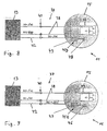
- Figs. 8 and 9 correspond to the embodiments of Figs. 6 and 7 , respectively.
- the embodiments of Figs. 8 and 9 provide an additional supply line 42 in the power cable 37 which allows to drive sound generating element 45 independent of the vibrating element 43, which can be advantageous in some applications.
- the amplifier is preferably arranged in the alerting device 15, for example as a part of the sound producing means 45.
- the alerting device 15 preferably is a completely analogue device in view of a simple and cost-effective set-up.
- the alerting device 15 preferably does not contain any other active electric or electronic components in addition to the vibrating element 43 and the sound producing means 45, in view of a simple, cost-effective and safety oriented set-up as explained in the foregoing.
Landscapes
- Physics & Mathematics (AREA)
- General Physics & Mathematics (AREA)
- Business, Economics & Management (AREA)
- Emergency Management (AREA)
- Engineering & Computer Science (AREA)
- Acoustics & Sound (AREA)
- Signal Processing (AREA)
- Alarm Systems (AREA)
Priority Applications (1)
| Application Number | Priority Date | Filing Date | Title |
|---|---|---|---|
| EP11005141A EP2444945A1 (de) | 2010-10-20 | 2011-06-24 | Warnsystem und -verfahren für schwerhörige oder taube Personen |
Applications Claiming Priority (2)
| Application Number | Priority Date | Filing Date | Title |
|---|---|---|---|
| EP10013812 | 2010-10-20 | ||
| EP11005141A EP2444945A1 (de) | 2010-10-20 | 2011-06-24 | Warnsystem und -verfahren für schwerhörige oder taube Personen |
Publications (1)
| Publication Number | Publication Date |
|---|---|
| EP2444945A1 true EP2444945A1 (de) | 2012-04-25 |
Family
ID=44342882
Family Applications (1)
| Application Number | Title | Priority Date | Filing Date |
|---|---|---|---|
| EP11005141A Withdrawn EP2444945A1 (de) | 2010-10-20 | 2011-06-24 | Warnsystem und -verfahren für schwerhörige oder taube Personen |
Country Status (1)
| Country | Link |
|---|---|
| EP (1) | EP2444945A1 (de) |
Citations (6)
| Publication number | Priority date | Publication date | Assignee | Title |
|---|---|---|---|---|
| CA1123945A (en) | 1979-06-19 | 1982-05-18 | Helen M. Walker | Vibration alarm device |
| JPH10197657A (ja) * | 1997-01-07 | 1998-07-31 | Mitsuru Hayakawa | ブルルン目覚しマクラ |
| JP2002065434A (ja) * | 2000-08-28 | 2002-03-05 | Eishin Denki Kk | Pztセラミックス圧電スピーカーを内蔵した枕 |
| WO2006060679A2 (en) * | 2004-12-03 | 2006-06-08 | Combustion Science & Engineering, Inc. | Method and apparatus for waking a person |
| US20070290817A1 (en) * | 2006-06-16 | 2007-12-20 | Yung-Ching Huang | Timing Pillow with Multiple Alerting Abilities |
| JP2008194148A (ja) | 2007-02-09 | 2008-08-28 | Takayuki Shibazaki | 枕カバーおよび枕 |
-
2011
- 2011-06-24 EP EP11005141A patent/EP2444945A1/de not_active Withdrawn
Patent Citations (6)
| Publication number | Priority date | Publication date | Assignee | Title |
|---|---|---|---|---|
| CA1123945A (en) | 1979-06-19 | 1982-05-18 | Helen M. Walker | Vibration alarm device |
| JPH10197657A (ja) * | 1997-01-07 | 1998-07-31 | Mitsuru Hayakawa | ブルルン目覚しマクラ |
| JP2002065434A (ja) * | 2000-08-28 | 2002-03-05 | Eishin Denki Kk | Pztセラミックス圧電スピーカーを内蔵した枕 |
| WO2006060679A2 (en) * | 2004-12-03 | 2006-06-08 | Combustion Science & Engineering, Inc. | Method and apparatus for waking a person |
| US20070290817A1 (en) * | 2006-06-16 | 2007-12-20 | Yung-Ching Huang | Timing Pillow with Multiple Alerting Abilities |
| JP2008194148A (ja) | 2007-02-09 | 2008-08-28 | Takayuki Shibazaki | 枕カバーおよび枕 |
Similar Documents
| Publication | Publication Date | Title |
|---|---|---|
| US5076260A (en) | Sensible body vibration | |
| ES2352724T3 (es) | Dispositivo para excitar una fuente de vibraciones. | |
| US4853674A (en) | Signalling apparatus for hearing impaired persons | |
| CN101536050B (zh) | 用于具有植入的听力辅助设备的听力受损个体的警报系统 | |
| US8526649B2 (en) | Providing notification sounds in a customizable manner | |
| EP1170709B1 (de) | Informationsübertragungsvorrichtung | |
| US7173881B1 (en) | Silent morning alarm | |
| US20020181336A1 (en) | Portable timer-alarm | |
| JPH1014195A (ja) | 報知用振動発生装置 | |
| US6281785B1 (en) | Vibration generator for notification and portable communication device using the vibration generator | |
| CN220778473U (zh) | 音频牙刷 | |
| WO1998057761A1 (en) | Annunciator | |
| JP3113946U (ja) | 警報システム、及び、テンポラル警報電圧発生装置 | |
| JP3493182B2 (ja) | 難聴者支援方法およびその装置 | |
| US7501935B2 (en) | Multi-frequency fire alarm sounder | |
| US20070290817A1 (en) | Timing Pillow with Multiple Alerting Abilities | |
| RU2406156C1 (ru) | Индивидуальное радиоканальное устройство оповещения | |
| CN108742010A (zh) | 一种基于骨传导的音乐枕头 | |
| CN108432159A (zh) | 信息提供装置以及信息提供系统 | |
| US20230384739A1 (en) | Wearable Wake Up Alarm System | |
| JP2006345212A (ja) | 着呼報知システム、携帯型通信装置及び携帯型電気機器 | |
| JP2004015681A (ja) | 通信機器及び通信機器の着信報知方法 | |
| KR200270757Y1 (ko) | 자명종 시계 | |
| CA2459954A1 (en) | Passive and active escapement for sound resonance | |
| JP6293252B2 (ja) | 補聴器 |
Legal Events
| Date | Code | Title | Description |
|---|---|---|---|
| AK | Designated contracting states |
Kind code of ref document: A1 Designated state(s): AL AT BE BG CH CY CZ DE DK EE ES FI FR GB GR HR HU IE IS IT LI LT LU LV MC MK MT NL NO PL PT RO RS SE SI SK SM TR |
|
| AX | Request for extension of the european patent |
Extension state: BA ME |
|
| PUAI | Public reference made under article 153(3) epc to a published international application that has entered the european phase |
Free format text: ORIGINAL CODE: 0009012 |
|
| STAA | Information on the status of an ep patent application or granted ep patent |
Free format text: STATUS: THE APPLICATION IS DEEMED TO BE WITHDRAWN |
|
| 18D | Application deemed to be withdrawn |
Effective date: 20121026 |