EP2445059A1 - Steckerabdeckung, Stecker und Montageverfahren dafür - Google Patents
Steckerabdeckung, Stecker und Montageverfahren dafür Download PDFInfo
- Publication number
- EP2445059A1 EP2445059A1 EP09009435A EP09009435A EP2445059A1 EP 2445059 A1 EP2445059 A1 EP 2445059A1 EP 09009435 A EP09009435 A EP 09009435A EP 09009435 A EP09009435 A EP 09009435A EP 2445059 A1 EP2445059 A1 EP 2445059A1
- Authority
- EP
- European Patent Office
- Prior art keywords
- wire
- connector
- guide portion
- wire guide
- hole
- Prior art date
- Legal status (The legal status is an assumption and is not a legal conclusion. Google has not performed a legal analysis and makes no representation as to the accuracy of the status listed.)
- Granted
Links
- 238000000034 method Methods 0.000 title claims description 11
- 238000005452 bending Methods 0.000 claims abstract description 23
- 238000010276 construction Methods 0.000 description 6
- 239000011347 resin Substances 0.000 description 3
- 229920005989 resin Polymers 0.000 description 3
- 230000002093 peripheral effect Effects 0.000 description 2
- 239000011248 coating agent Substances 0.000 description 1
- 238000000576 coating method Methods 0.000 description 1
- 230000001419 dependent effect Effects 0.000 description 1
- 238000011156 evaluation Methods 0.000 description 1
- 238000011056 performance test Methods 0.000 description 1
- XLYOFNOQVPJJNP-UHFFFAOYSA-N water Substances O XLYOFNOQVPJJNP-UHFFFAOYSA-N 0.000 description 1
Images




Classifications
-
- H—ELECTRICITY
- H01—ELECTRIC ELEMENTS
- H01R—ELECTRICALLY-CONDUCTIVE CONNECTIONS; STRUCTURAL ASSOCIATIONS OF A PLURALITY OF MUTUALLY-INSULATED ELECTRICAL CONNECTING ELEMENTS; COUPLING DEVICES; CURRENT COLLECTORS
- H01R13/00—Details of coupling devices of the kinds covered by groups H01R12/70 or H01R24/00 - H01R33/00
- H01R13/58—Means for relieving strain on wire connection, e.g. cord grip, for avoiding loosening of connections between wires and terminals within a coupling device terminating a cable
- H01R13/5833—Means for relieving strain on wire connection, e.g. cord grip, for avoiding loosening of connections between wires and terminals within a coupling device terminating a cable the cable being forced in a tortuous or curved path, e.g. knots in cable
-
- H—ELECTRICITY
- H01—ELECTRIC ELEMENTS
- H01R—ELECTRICALLY-CONDUCTIVE CONNECTIONS; STRUCTURAL ASSOCIATIONS OF A PLURALITY OF MUTUALLY-INSULATED ELECTRICAL CONNECTING ELEMENTS; COUPLING DEVICES; CURRENT COLLECTORS
- H01R13/00—Details of coupling devices of the kinds covered by groups H01R12/70 or H01R24/00 - H01R33/00
- H01R13/46—Bases; Cases
- H01R13/50—Bases; Cases formed as an integral body
- H01R13/501—Bases; Cases formed as an integral body comprising an integral hinge or a frangible part
-
- H—ELECTRICITY
- H01—ELECTRIC ELEMENTS
- H01R—ELECTRICALLY-CONDUCTIVE CONNECTIONS; STRUCTURAL ASSOCIATIONS OF A PLURALITY OF MUTUALLY-INSULATED ELECTRICAL CONNECTING ELEMENTS; COUPLING DEVICES; CURRENT COLLECTORS
- H01R13/00—Details of coupling devices of the kinds covered by groups H01R12/70 or H01R24/00 - H01R33/00
- H01R13/46—Bases; Cases
- H01R13/52—Dustproof, splashproof, drip-proof, waterproof, or flameproof cases
- H01R13/5205—Sealing means between cable and housing, e.g. grommet
Definitions
- the present invention relates to a connector cover formed by a pair of cover (preferably half) pieces to be mounted a connector housing, preferably on a rear part of a connector housing, to a connector provided therewith and to a method of assembling such connector.
- a connector cover disclosed in Japanese Unexamined Patent Publication No. H09-293556 is, for example, known as the one of this type.
- a rubber plug is mounted in a rear end portion of a connector housing.
- the connector cover is formed such that a wire drawn out backward through a through hole of a rubber plug is folded to extend forward by being brought into contact with an inner wall of the connector cover and then folded again to extend backward.
- the reason for folding the wire twice is that the entire length of the connector cover becomes longer if the wire is not folded and the connector cover is more subjected to an external force to be broken.
- the entire length of the connector cover is shortened by bending the wire in the connector cover.
- the present invention was developed in view of the above situation and an object thereof is to reduce a variation of sealability by a rubber plug.
- a connector cover comprised of a pair of cover pieces and to be mounted on a connector housing, comprising:
- the wire drawn out from the through hole of the resilient plug can be bent by the second wire guide portion in the direction substantially opposite to the bending direction by the first wire guide portion.
- the wire can be drawn out substantially straight by the pair of ribs without being bent immediately after coming out from the resilient plug, an overall sealability of the resilient plug can be improved, particularly a variation of sealability by the resilient plug can be reduced.
- the first wire guide portion includes a pair of upper and lower ribs formed in one half piece.
- a connector cover comprised of a pair of half pieces and to be mounted on a rear part of a connector housing, comprising:
- the wire drawn out backward from the through hole of the rubber plug can be bent by the second wire guide portion in the direction opposite to the bending direction by the first wire guide portion.
- the wire can be drawn out straight by the pair of ribs without being bent immediately after coming out from the rubber plug, a variation of sealability by the rubber plug can be reduced.
- the present invention is preferably embodied as follows.
- the second wire guide portion may include a wire accommodating groove for at least partly accommodating the wire with a part of the wire exposed.
- the second wire portion may be provided on one cover piece and the other cover piece may include at least one supporting portion for supporting an exposed part of the wire.
- the second wire guide portion may include a wire accommodating groove for accommodating the wire with a part of the wire exposed, and the other half piece may include a supporting portion for supporting an exposed part of the wire.
- the wire can be prevented from coming out of the wire accommodating groove since the exposed part of the wire accommodated in the wire accommodating groove can be supported by the supporting portion.
- the second wire guide portion may be arranged side by side with the first wire guide portion in a direction at an angle different from 0° or 180°, preferably substantially orthogonal to a direction of the extension.
- the entire length of the connector cover can be shortened in forward and backward directions.
- One or more pressing ribs may be provided in or at the wire accommodating groove to hold the wire press-fitted in the wire accommodating groove.
- the wire can be held press-fitted in the wire accommodating groove by being pressed by the pressing ribs.
- At least one protection wall for protecting the wire substantially from front by being arranged before the bent parts of the wire may be provided in the connector cover and preferably projects from the other cover piece.
- the wire may be bent by the first and second wire guide portions to substantially have a mirrored S- or Z-shape.
- the two cover pieces may be formed integral to each other by means of at least one hinge portion.
- a locking structure may be provided for locking the two cover pieces in the assembled state.
- a connector comprising:
- the present invention is preferably embodied as follows.
- the method may further comprise a step of at least partly accommodating the wire in a wire accommodating groove of the second wire guide portion with a part of the wire exposed.
- the method may further comprise a step of supporting an exposed part of the wire by means of at least one supporting portion, wherein the second wire portion preferably is provided on one cover piece and the supporting portion preferably is provided on the other cover piece.
- the method may further comprise a step of holding the wire at least partly press-fitted in the wire accommodating groove by means of one or more pressing ribs provided in or at the wire accommodating groove.
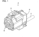
- FIG. 1 is a perspective view showing a state where a connector cover 10 of this embodiment is mounted on (preferably a rear part of) a connector 50.
- the connector cover 10 is formed by assembling at least one pair of half pieces 20, 30 (as preferred cover pieces) preferably integrally or unitarily being formed by being connected via at least one flexible hinge portion 40. It should be understood that the connector cover 10 may be subdivided into three or more pieces preferably connected by respective hinge portions or that the connector cover 10 may be divided into two cover pieces not being half pieces, i.e. respectively spanning a circumference portion being different from half the circumference of the complete connector cover 10.
- the connector cover 10 includes a connector accommodating portion 11 in the form of a hood having an open front side and adapted to at least partly accommodate a connector housing 51 of the connector 50 and a wire accommodating portion 12 for at least partly accommodating a wire W drawn out from a draw out surface (preferably substantially backward) from the connector housing 51.
- one or more, preferably a pair of housing locking portions 52 project from the (preferably substantially opposite) lateral (left and/or right) side(s) of (preferably a rear end portion 51 R of) the connector housing 51.
- These one or more housing locking portions 52 can lock the connector housing 51 in forward and backward directions by being fitted into one or more respective retaining holes 13 formed to penetrate (preferably substantially opposite) side surface portion(s) 11 S of the connector accommodating portion 11.
- one or more lock portions are provided at one or more (e.g. three) separate positions of lateral (upper and/or lower) sides of the connector cover 10.
- the first lock portion is provided on a lateral (preferably upper) surface portion 11 U of the connector accommodating portion 11.
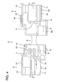
- This first lock portion preferably is made up of or comprises a first lock projection 14A provided on one cover (half) piece 20 and a first lock hole or recess 14B formed in the other cover (half) piece 30 as shown in FIG. 4 .
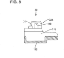
- FIG. 8 is a view (section along A-A of FIG. 4 ) of the first lock hole 14B of the other cover (half) piece 30 when viewed from below.
- the first lock hole 14B is substantially formed to radially or vertically penetrate a first lock piece 32A projecting from an other contact portion 31 which comes into contact with one contact portion 21 of the one cover (half) piece 20.
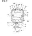
- the first lock projection 14A is to be engaged with an inner peripheral wall (lock piece 32A) of the first lock hole 14B substantially in a lateral direction in a contact state of the both contact portions 21, 31 shown in FIG. 9 .
- the second lock portion is provided on a lateral (preferably lower) surface portion 11 L (particularly different from that where the first lock portion is provided) of the connector accommodating portion 11.
- This second lock portion preferably is made up of or comprises a second lock projection 15A provided on the one cover (half) piece 20 and a second lock hole 15B formed in the other cover (half) piece 30 as shown in FIG. 4 .
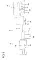
- the second lock hole 15B is substantially formed to radially vertically penetrate a second lock piece 32B projecting from the other contact portion 31 as shown in FIG. 7 .
- the second lock projection 15A is to be engaged with an inner peripheral wall (lock piece 32B) of the second lock hole 15B in the lateral direction in a contact state of the both contact portions 21, 31 shown in FIG. 10 .
- the third lock portion is provided on a supporting portion 12L forming a lateral or lower side of the wire accommodating portion 12.
- This third lock portion preferably is made up of or comprises a third lock projection 16A provided on the one cover (half) piece 20 and a third lock hole 16B formed in the other cover (half) piece 30 as shown in FIG. 4 .
- the third lock hole 16B is substantially formed to radially or vertically penetrate preferably by laterally cutting a part of the supporting portion 12L excluding the leading end as shown in FIG. 6 .
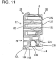
- the third lock projection 16A is to be engaged with an inner wall (leading end of the supporting portion 12L) forming the third lock hole 16B substantially in the lateral direction as shown in FIG. 11 .
- a resilient or rubber plug mount hole (not shown), into which a resilient or rubber plug 60 at least partly is to be mounted, is formed to penetrate the rear end portion 51 R of the connector housing 51 in forward and backward directions.
- the rear end of the resilient or rubber plug mount hole is located at a position substantially aligned with the rear end portion 51 R of the connector housing 51 in forward and backward directions.
- the resilient or rubber plug mount hole is so formed behind or adjacent to a cavity for at least partly accommodating a terminal fitting (not shown) as to communicate with the cavity.
- the resilient or rubber plug 60 is so to be mounted as to at least partly project backward from the rear end of the resilient or rubber plug mount hole.
- the advantage of mounting the resilient or rubber plug 60 in such a state is that a clearance is unlikely to be formed between the resilient or rubber plug 60 and the resilient or rubber plug mount hole or between the wire W and the through hole 61 when the wire W is shaken and/or water is unlikely to penetrate into the cavity through the resilient or rubber plug mount hole.
- a first wire guide portion 22 is provided near the resilient or rubber plug 60 in the one cover (half) piece 20.
- the first wire guide portion 22 includes one or more, preferably a pair of (upper and/or lower) ribs 22U, 22L preferably arranged to substantially face each other or substantially correspond to each other.
- the both ribs 22U, 22L project from a side surface portion 12S of the wire accommodating portion 12.
- the both ribs 22U, 22L preferably are respectively arranged at positions above and below (or substantially laterally opposite with respect to) an extension L of the axial center of the through hole 61.
- the wire W of this embodiment preferably is formed by bundling two small-diameter wires W1 and sheathing these small-diameter wires W1 with insulating resin.
- the small-diameter wires W1 are at least partly exposed by removing the insulating resin at or near an end portion of the wire W.
- cores are at least partly exposed by removing coating(s) made of insulating resin at end portions of the respective small-diameter wires W and these cores are connected (preferably crimp-connected) with (preferably a barrel of) the terminal fitting to electrically connect the cores and the terminal fitting.
- a (preferably substantially R-shaped) bending surface is formed on or at the rear end of the lower rib 22L.
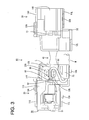
- the small-diameter wires W1 drawn out backward from the through hole 61 of the resilient or rubber plug 60 are bent to extend at an angle different from 0° or 180°, preferably substantially more than 90° and/or substantially obliquely forward by the bending surface.
- a second wire guide portion 23 is provided below or adjacent to the lower rib 22L in the side surface portions 12S of the wire accommodating portion 12.
- the second wire guide portion 23 is arranged side by side with the first wire guide portion 22 in a direction (vertical direction) at an angle different from 0° or 180°, preferably substantially orthogonal to a direction of the extension L and/or adjacent to the lower rib 22L substantially opposite to the upper rib 22U.
- the second wire guide portion 23 is formed with a wire accommodating groove 23A preferably with a substantially open lower side.
- One or more, preferably a plurality of pressing ribs 23B are so provided on (preferably the substantially opposite lateral (left and/or right) sides of) the inner wall of the wire accommodating groove 23A as preferably to substantially face each other.
- the wire W is press-fitted in the wire accommodating groove 23A. Ends of the small-diameter wires W1 toward the sheathed part of the wire W preferably are located at positions slightly before the front end of the second wire guide portion 23.
- a lower part of the wire W preferably is substantially exposed.
- the supporting portion 12L is arranged below the wire accommodating groove 23A, the exposed part of the wire W can be supported and/or at least partly covered by the supporting portion 12L and the wire W can be held in the wire accommodating groove 23A.
- the small-diameter wires W bent to extent obliquely forward by the first wire guide portion 22 are bent to extend substantially backward at the position before the second wire guide portion 23.
- the small-diameter wires W preferably are bent to substantially have a mirrored S- or Z-shape (see FIG. 3 ).
- a protection wall 33 for protecting the small-diameter wires W1 substantially from front by being arranged before the bent parts of the small-diameter wires W1 preferably projects from the other cover (half) piece 30.
- the connector 50 having the wire W at least partly mounted therein is mounted on the inner surface of the one cover (half) piece 20 to fit or engage the housing locking portion(s) 52 into the retaining hole(s) 13.
- the small-diameter wires W1 drawn out substantially backward from the through hole 61 of the resilient or rubber plug 60 are passed adjacent to the lower rib 22L (preferably at least partly between the two ribs 22U, 22L) and folded back or bent by the bending surface at the rear end of the lower rib 22L, thereby preferably being bent to extend obliquely forward.
- the small-diameter wires W1 are bent to extend substantially backward at the position before the second wire guide portion 23 and the wire W at least partly is pushed into the wire accommodating groove 23A. At this time, the wire W preferably is held while being pressed by the pressing ribs 23B.
- the two cover (half) pieces 20, 30 are assembled with each other preferably by bending the hinge portion 40 to at least partly cover the connector 50 by the other cover (half) piece 30.
- the housing locking portion(s) 52 is/are at least partly fitted into or engaged with the retaining hole(s) 13 of the other cover (half) piece 30, particularly the first lock projection 14A is at least partly fitted into the first lock hole 14B, the second lock projection 15A is at least partly fitted into the second lock hole 15B and the third lock projection 16A is at least partly fitted into the third lock hole 16B.
- the connector cover 10 is formed by the two cover (half) pieces 20, 30 and the connector 50 is so held in the connector accommodating portion 11 as not to come out.
- the small-diameter wires W1 and the wire W are at least partly covered by the wire accommodating portion 12.
- the small-diameter wires W1 can be protected from external objects e.g. flying stones and the like.
- a waterproof performance test is conducted for the connector 50 mounted with the connector cover 10 in this way by conducting a sealability test. Specifically, air is fed into the cavity of the connector 50 mounted with the connector cover 10 and an air pressure at which air leakage occurs is measured, whereby sealability is evaluated. Since the small-diameter wires W1 drawn out backward from the through hole 61 of the resilient or rubber plug 60 preferably are held straight by the both ribs 22U, 22L arranged near the resilient or rubber plug 60 without being immediately bent in this embodiment, a clearance is unlikely to be formed between the resilient or rubber plug 60 and the resilient or rubber plug mount hole and/or between the small-diameter wires W1 and the through hole 61 of the resilient or rubber plug 60 and air leakage is unlikely to occur. Thus, an air pressure variation can be reduced.
- the pair of ribs 22U, 22L at the opposite sides of the extension L of the axial center of the through hole 61 preferably are provided near the resilient or rubber plug 60 in this embodiment, the small-diameter wires W1 drawn out backward from the through hole 61 can be held substantially straight and a variation of the sealability by the resilient or rubber plug 60 can be reduced.
- the wire W accommodated in the wire accommodating groove 23A of the second wire guide portion 23 can be supported. Further, the wire W can be press-fitted in the wire accommodating groove 23A by the pressing ribs 23B.
- the wire accommodating portion 12 can be made smaller in forward and backward directions and can avoid interference with other members.
- a connector cover 10 is comprised of two or more cover pieces (preferably a pair of cover (preferably half) pieces) 20, 30 and to be mounted on or to (preferably a rear part of) a connector housing 51.
- the connector cover 10 is provided with a first wire guide portion 22 preferably including a pair of firts and second (upper and lower) ribs 20U, 20L formed in one cover (half) piece 20, arranged near a resilient or rubber plug 60 mounted in a rear end portion of the connector housing 51 and preferably positioned at the substantially opposite sides of an extension L of the axial line of a through hole 61 of the resilient or rubber plug 60, through which hole a wire W is to be inserted, and adapted to bend small-diameter wires W1 drawn out backward from the through hole 61, and a second wire guide portion 23 for bending the small-diameter wires W1 bent by the first wire guide portion 22 in a direction opposite to a bending direction by the first wire guide portion 22.
- a first wire guide portion 22 preferably including a pair of firts and second (upper and lower) ribs 20U, 20L formed in one cover (half) piece 20, arranged near a resilient or rubber plug 60 mounted in a rear end portion
Landscapes
- Details Of Connecting Devices For Male And Female Coupling (AREA)
- Connector Housings Or Holding Contact Members (AREA)
Applications Claiming Priority (1)
| Application Number | Priority Date | Filing Date | Title |
|---|---|---|---|
| JP2008227405A JP5115408B2 (ja) | 2008-09-04 | 2008-09-04 | コネクタカバー |
Publications (2)
| Publication Number | Publication Date |
|---|---|
| EP2445059A1 true EP2445059A1 (de) | 2012-04-25 |
| EP2445059B1 EP2445059B1 (de) | 2014-08-20 |
Family
ID=41726126
Family Applications (1)
| Application Number | Title | Priority Date | Filing Date |
|---|---|---|---|
| EP09009435.0A Not-in-force EP2445059B1 (de) | 2008-09-04 | 2009-07-21 | Steckerabdeckung, Stecker und Montageverfahren dafür |
Country Status (4)
| Country | Link |
|---|---|
| US (1) | US7806717B2 (de) |
| EP (1) | EP2445059B1 (de) |
| JP (1) | JP5115408B2 (de) |
| CN (1) | CN101667691B (de) |
Families Citing this family (13)
| Publication number | Priority date | Publication date | Assignee | Title |
|---|---|---|---|---|
| US8272114B2 (en) * | 2010-09-03 | 2012-09-25 | Cheng Uei Precision Industry Co., Ltd. | Connector cover assembling system |
| JP5651505B2 (ja) * | 2011-03-10 | 2015-01-14 | 矢崎総業株式会社 | 電線引き出し部分の防水構造 |
| JP5654412B2 (ja) * | 2011-04-28 | 2015-01-14 | 住友電装株式会社 | 横出しコネクタ用のカバー |
| WO2013069107A1 (ja) * | 2011-11-09 | 2013-05-16 | 富士電線工業株式会社 | プラグの電線配線構造 |
| JP6056706B2 (ja) * | 2013-08-23 | 2017-01-11 | 住友電装株式会社 | コネクタ |
| JP6179451B2 (ja) * | 2014-04-28 | 2017-08-16 | 住友電装株式会社 | コネクタ |
| JP6255326B2 (ja) * | 2014-10-02 | 2017-12-27 | 矢崎総業株式会社 | 電線係止装置 |
| JP6076319B2 (ja) * | 2014-11-27 | 2017-02-08 | 矢崎総業株式会社 | カバー、及び、ハウジングとカバーとの接続構造 |
| EP3057182B1 (de) * | 2015-02-12 | 2019-04-03 | Aptiv Technologies Limited | Verbinder mit vormontiertem Leitungsadapter |
| JP6570897B2 (ja) * | 2015-06-30 | 2019-09-04 | ダイハツ工業株式会社 | 電線経路規制用カバー |
| US10527464B2 (en) * | 2016-08-18 | 2020-01-07 | Ford Global Technologies, Llc | Rotatable sensor cover |
| JP7004214B2 (ja) * | 2018-03-13 | 2022-01-21 | 住友電装株式会社 | コネクタカバー |
| CN111207441A (zh) * | 2020-02-25 | 2020-05-29 | 珠海格力电器股份有限公司 | 底部结构及电暖器 |
Citations (5)
| Publication number | Priority date | Publication date | Assignee | Title |
|---|---|---|---|---|
| JPH09293556A (ja) * | 1996-04-25 | 1997-11-11 | Sumitomo Wiring Syst Ltd | コネクタ |
| US5830006A (en) * | 1996-01-22 | 1998-11-03 | Yazaki Corporation | Connector with rear holder |
| EP1041682A1 (de) * | 1999-03-29 | 2000-10-04 | Japan Aviation Electronics Industry, Limited | Kabelstecker in welchem zwei Kontakten einen Drahtkern eines Kabels zwischen sich befestigen |
| US20020025713A1 (en) * | 2000-08-28 | 2002-02-28 | Masaaki Tabata | Connector |
| WO2006131607A1 (fr) * | 2005-06-06 | 2006-12-14 | Fci | Dispositif de reprise d'efforts pour cables de connecteur electrique |
Family Cites Families (6)
| Publication number | Priority date | Publication date | Assignee | Title |
|---|---|---|---|---|
| JPS5890677U (ja) * | 1981-12-15 | 1983-06-20 | 富士フアコム制御株式会社 | ケ−ブル固定装置 |
| JPH09102360A (ja) * | 1995-10-05 | 1997-04-15 | Sumitomo Wiring Syst Ltd | 電線カバー付きコネクタ |
| JP3134780B2 (ja) * | 1996-07-15 | 2001-02-13 | 住友電装株式会社 | コネクタカバー |
| JP2001509948A (ja) * | 1997-01-30 | 2001-07-24 | バーグ・テクノロジー・インコーポレーテッド | ケーブルコネクタ |
| JP4043772B2 (ja) * | 2001-12-04 | 2008-02-06 | 株式会社オートネットワーク技術研究所 | 電気接続箱 |
| JP4830770B2 (ja) * | 2006-10-06 | 2011-12-07 | 住友電装株式会社 | 電線ホルダ |
-
2008
- 2008-09-04 JP JP2008227405A patent/JP5115408B2/ja not_active Expired - Fee Related
-
2009
- 2009-07-21 EP EP09009435.0A patent/EP2445059B1/de not_active Not-in-force
- 2009-08-26 US US12/547,864 patent/US7806717B2/en active Active
- 2009-08-28 CN CN200910170604XA patent/CN101667691B/zh not_active Expired - Fee Related
Patent Citations (5)
| Publication number | Priority date | Publication date | Assignee | Title |
|---|---|---|---|---|
| US5830006A (en) * | 1996-01-22 | 1998-11-03 | Yazaki Corporation | Connector with rear holder |
| JPH09293556A (ja) * | 1996-04-25 | 1997-11-11 | Sumitomo Wiring Syst Ltd | コネクタ |
| EP1041682A1 (de) * | 1999-03-29 | 2000-10-04 | Japan Aviation Electronics Industry, Limited | Kabelstecker in welchem zwei Kontakten einen Drahtkern eines Kabels zwischen sich befestigen |
| US20020025713A1 (en) * | 2000-08-28 | 2002-02-28 | Masaaki Tabata | Connector |
| WO2006131607A1 (fr) * | 2005-06-06 | 2006-12-14 | Fci | Dispositif de reprise d'efforts pour cables de connecteur electrique |
Also Published As
| Publication number | Publication date |
|---|---|
| JP2010062034A (ja) | 2010-03-18 |
| US7806717B2 (en) | 2010-10-05 |
| CN101667691B (zh) | 2012-11-14 |
| US20100055963A1 (en) | 2010-03-04 |
| JP5115408B2 (ja) | 2013-01-09 |
| EP2445059B1 (de) | 2014-08-20 |
| CN101667691A (zh) | 2010-03-10 |
Similar Documents
| Publication | Publication Date | Title |
|---|---|---|
| EP2445059B1 (de) | Steckerabdeckung, Stecker und Montageverfahren dafür | |
| JP5534350B2 (ja) | コネクタ装置 | |
| US10476178B2 (en) | Cable mounting member, cable mounting member with cable and connector | |
| CN101385205B (zh) | 电连接器组装体 | |
| CN104682087A (zh) | 连接器 | |
| JP3763574B2 (ja) | コネクタ | |
| JP2001155810A (ja) | コネクタ | |
| JP6709817B2 (ja) | コネクタ | |
| CN100486045C (zh) | 电连接器 | |
| JP2001250621A (ja) | 接続端子 | |
| CN114586245B (zh) | 缆线连接器组件 | |
| CN109256642B (zh) | 连接器后壳组件 | |
| WO2017217208A9 (ja) | コネクタ | |
| CN111211432B (zh) | 连接器 | |
| JP2001250622A (ja) | 接続端子 | |
| US7654865B2 (en) | Electrical connector | |
| CN106257764B (zh) | 带定位板的连接器 | |
| CN104335428A (zh) | 电线保护罩 | |
| US20060116017A1 (en) | Electrical connector housing, electrical connector, and connector assembly | |
| JP6943917B2 (ja) | コネクタ | |
| JP7283946B2 (ja) | コネクタハウジング、及び、コネクタハウジング付き電線 | |
| JP2008293859A (ja) | プロテクタ付きコネクタ | |
| JP5278145B2 (ja) | コネクタ | |
| JP7011785B2 (ja) | 端子金具およびコネクタ | |
| JP7198415B2 (ja) | カバー |
Legal Events
| Date | Code | Title | Description |
|---|---|---|---|
| 17P | Request for examination filed |
Effective date: 20090730 |
|
| AK | Designated contracting states |
Kind code of ref document: A1 Designated state(s): AT BE BG CH CY CZ DE DK EE ES FI FR GB GR HR HU IE IS IT LI LT LU LV MC MK MT NL NO PL PT RO SE SI SK SM TR |
|
| AX | Request for extension of the european patent |
Extension state: AL BA RS |
|
| PUAI | Public reference made under article 153(3) epc to a published international application that has entered the european phase |
Free format text: ORIGINAL CODE: 0009012 |
|
| GRAP | Despatch of communication of intention to grant a patent |
Free format text: ORIGINAL CODE: EPIDOSNIGR1 |
|
| RIC1 | Information provided on ipc code assigned before grant |
Ipc: H01R 13/50 20060101ALN20140220BHEP Ipc: H01R 13/52 20060101ALN20140220BHEP Ipc: H01R 13/58 20060101AFI20140220BHEP |
|
| INTG | Intention to grant announced |
Effective date: 20140312 |
|
| GRAS | Grant fee paid |
Free format text: ORIGINAL CODE: EPIDOSNIGR3 |
|
| GRAA | (expected) grant |
Free format text: ORIGINAL CODE: 0009210 |
|
| AK | Designated contracting states |
Kind code of ref document: B1 Designated state(s): AT BE BG CH CY CZ DE DK EE ES FI FR GB GR HR HU IE IS IT LI LT LU LV MC MK MT NL NO PL PT RO SE SI SK SM TR |
|
| REG | Reference to a national code |
Ref country code: GB Ref legal event code: FG4D |
|
| REG | Reference to a national code |
Ref country code: CH Ref legal event code: EP |
|
| REG | Reference to a national code |
Ref country code: AT Ref legal event code: REF Ref document number: 683902 Country of ref document: AT Kind code of ref document: T Effective date: 20140915 |
|
| REG | Reference to a national code |
Ref country code: IE Ref legal event code: FG4D |
|
| REG | Reference to a national code |
Ref country code: DE Ref legal event code: R096 Ref document number: 602009026079 Country of ref document: DE Effective date: 20141002 |
|
| REG | Reference to a national code |
Ref country code: AT Ref legal event code: MK05 Ref document number: 683902 Country of ref document: AT Kind code of ref document: T Effective date: 20140820 |
|
| REG | Reference to a national code |
Ref country code: NL Ref legal event code: VDEP Effective date: 20140820 |
|
| REG | Reference to a national code |
Ref country code: LT Ref legal event code: MG4D |
|
| PG25 | Lapsed in a contracting state [announced via postgrant information from national office to epo] |
Ref country code: LT Free format text: LAPSE BECAUSE OF FAILURE TO SUBMIT A TRANSLATION OF THE DESCRIPTION OR TO PAY THE FEE WITHIN THE PRESCRIBED TIME-LIMIT Effective date: 20140820 Ref country code: NO Free format text: LAPSE BECAUSE OF FAILURE TO SUBMIT A TRANSLATION OF THE DESCRIPTION OR TO PAY THE FEE WITHIN THE PRESCRIBED TIME-LIMIT Effective date: 20141120 Ref country code: SE Free format text: LAPSE BECAUSE OF FAILURE TO SUBMIT A TRANSLATION OF THE DESCRIPTION OR TO PAY THE FEE WITHIN THE PRESCRIBED TIME-LIMIT Effective date: 20140820 Ref country code: PT Free format text: LAPSE BECAUSE OF FAILURE TO SUBMIT A TRANSLATION OF THE DESCRIPTION OR TO PAY THE FEE WITHIN THE PRESCRIBED TIME-LIMIT Effective date: 20141222 Ref country code: ES Free format text: LAPSE BECAUSE OF FAILURE TO SUBMIT A TRANSLATION OF THE DESCRIPTION OR TO PAY THE FEE WITHIN THE PRESCRIBED TIME-LIMIT Effective date: 20140820 Ref country code: BG Free format text: LAPSE BECAUSE OF FAILURE TO SUBMIT A TRANSLATION OF THE DESCRIPTION OR TO PAY THE FEE WITHIN THE PRESCRIBED TIME-LIMIT Effective date: 20141120 Ref country code: GR Free format text: LAPSE BECAUSE OF FAILURE TO SUBMIT A TRANSLATION OF THE DESCRIPTION OR TO PAY THE FEE WITHIN THE PRESCRIBED TIME-LIMIT Effective date: 20141121 Ref country code: FI Free format text: LAPSE BECAUSE OF FAILURE TO SUBMIT A TRANSLATION OF THE DESCRIPTION OR TO PAY THE FEE WITHIN THE PRESCRIBED TIME-LIMIT Effective date: 20140820 |
|
| PG25 | Lapsed in a contracting state [announced via postgrant information from national office to epo] |
Ref country code: LV Free format text: LAPSE BECAUSE OF FAILURE TO SUBMIT A TRANSLATION OF THE DESCRIPTION OR TO PAY THE FEE WITHIN THE PRESCRIBED TIME-LIMIT Effective date: 20140820 Ref country code: IS Free format text: LAPSE BECAUSE OF FAILURE TO SUBMIT A TRANSLATION OF THE DESCRIPTION OR TO PAY THE FEE WITHIN THE PRESCRIBED TIME-LIMIT Effective date: 20141220 Ref country code: HR Free format text: LAPSE BECAUSE OF FAILURE TO SUBMIT A TRANSLATION OF THE DESCRIPTION OR TO PAY THE FEE WITHIN THE PRESCRIBED TIME-LIMIT Effective date: 20140820 Ref country code: AT Free format text: LAPSE BECAUSE OF FAILURE TO SUBMIT A TRANSLATION OF THE DESCRIPTION OR TO PAY THE FEE WITHIN THE PRESCRIBED TIME-LIMIT Effective date: 20140820 |
|
| PG25 | Lapsed in a contracting state [announced via postgrant information from national office to epo] |
Ref country code: NL Free format text: LAPSE BECAUSE OF FAILURE TO SUBMIT A TRANSLATION OF THE DESCRIPTION OR TO PAY THE FEE WITHIN THE PRESCRIBED TIME-LIMIT Effective date: 20140820 |
|
| PG25 | Lapsed in a contracting state [announced via postgrant information from national office to epo] |
Ref country code: IT Free format text: LAPSE BECAUSE OF FAILURE TO SUBMIT A TRANSLATION OF THE DESCRIPTION OR TO PAY THE FEE WITHIN THE PRESCRIBED TIME-LIMIT Effective date: 20140820 Ref country code: DK Free format text: LAPSE BECAUSE OF FAILURE TO SUBMIT A TRANSLATION OF THE DESCRIPTION OR TO PAY THE FEE WITHIN THE PRESCRIBED TIME-LIMIT Effective date: 20140820 Ref country code: RO Free format text: LAPSE BECAUSE OF FAILURE TO SUBMIT A TRANSLATION OF THE DESCRIPTION OR TO PAY THE FEE WITHIN THE PRESCRIBED TIME-LIMIT Effective date: 20140820 Ref country code: EE Free format text: LAPSE BECAUSE OF FAILURE TO SUBMIT A TRANSLATION OF THE DESCRIPTION OR TO PAY THE FEE WITHIN THE PRESCRIBED TIME-LIMIT Effective date: 20140820 Ref country code: SK Free format text: LAPSE BECAUSE OF FAILURE TO SUBMIT A TRANSLATION OF THE DESCRIPTION OR TO PAY THE FEE WITHIN THE PRESCRIBED TIME-LIMIT Effective date: 20140820 Ref country code: CZ Free format text: LAPSE BECAUSE OF FAILURE TO SUBMIT A TRANSLATION OF THE DESCRIPTION OR TO PAY THE FEE WITHIN THE PRESCRIBED TIME-LIMIT Effective date: 20140820 |
|
| REG | Reference to a national code |
Ref country code: DE Ref legal event code: R097 Ref document number: 602009026079 Country of ref document: DE |
|
| PG25 | Lapsed in a contracting state [announced via postgrant information from national office to epo] |
Ref country code: PL Free format text: LAPSE BECAUSE OF FAILURE TO SUBMIT A TRANSLATION OF THE DESCRIPTION OR TO PAY THE FEE WITHIN THE PRESCRIBED TIME-LIMIT Effective date: 20140820 |
|
| PLBE | No opposition filed within time limit |
Free format text: ORIGINAL CODE: 0009261 |
|
| STAA | Information on the status of an ep patent application or granted ep patent |
Free format text: STATUS: NO OPPOSITION FILED WITHIN TIME LIMIT |
|
| 26N | No opposition filed |
Effective date: 20150521 |
|
| PG25 | Lapsed in a contracting state [announced via postgrant information from national office to epo] |
Ref country code: SI Free format text: LAPSE BECAUSE OF FAILURE TO SUBMIT A TRANSLATION OF THE DESCRIPTION OR TO PAY THE FEE WITHIN THE PRESCRIBED TIME-LIMIT Effective date: 20140820 |
|
| PG25 | Lapsed in a contracting state [announced via postgrant information from national office to epo] |
Ref country code: MC Free format text: LAPSE BECAUSE OF FAILURE TO SUBMIT A TRANSLATION OF THE DESCRIPTION OR TO PAY THE FEE WITHIN THE PRESCRIBED TIME-LIMIT Effective date: 20140820 |
|
| REG | Reference to a national code |
Ref country code: CH Ref legal event code: PL |
|
| GBPC | Gb: european patent ceased through non-payment of renewal fee |
Effective date: 20150721 |
|
| PG25 | Lapsed in a contracting state [announced via postgrant information from national office to epo] |
Ref country code: LU Free format text: LAPSE BECAUSE OF FAILURE TO SUBMIT A TRANSLATION OF THE DESCRIPTION OR TO PAY THE FEE WITHIN THE PRESCRIBED TIME-LIMIT Effective date: 20150721 |
|
| REG | Reference to a national code |
Ref country code: IE Ref legal event code: MM4A |
|
| PG25 | Lapsed in a contracting state [announced via postgrant information from national office to epo] |
Ref country code: GB Free format text: LAPSE BECAUSE OF NON-PAYMENT OF DUE FEES Effective date: 20150721 Ref country code: CH Free format text: LAPSE BECAUSE OF NON-PAYMENT OF DUE FEES Effective date: 20150731 Ref country code: LI Free format text: LAPSE BECAUSE OF NON-PAYMENT OF DUE FEES Effective date: 20150731 |
|
| REG | Reference to a national code |
Ref country code: FR Ref legal event code: PLFP Year of fee payment: 8 |
|
| PG25 | Lapsed in a contracting state [announced via postgrant information from national office to epo] |
Ref country code: BE Free format text: LAPSE BECAUSE OF FAILURE TO SUBMIT A TRANSLATION OF THE DESCRIPTION OR TO PAY THE FEE WITHIN THE PRESCRIBED TIME-LIMIT Effective date: 20140820 Ref country code: IE Free format text: LAPSE BECAUSE OF NON-PAYMENT OF DUE FEES Effective date: 20150721 |
|
| PG25 | Lapsed in a contracting state [announced via postgrant information from national office to epo] |
Ref country code: MT Free format text: LAPSE BECAUSE OF FAILURE TO SUBMIT A TRANSLATION OF THE DESCRIPTION OR TO PAY THE FEE WITHIN THE PRESCRIBED TIME-LIMIT Effective date: 20140820 |
|
| PG25 | Lapsed in a contracting state [announced via postgrant information from national office to epo] |
Ref country code: HU Free format text: LAPSE BECAUSE OF FAILURE TO SUBMIT A TRANSLATION OF THE DESCRIPTION OR TO PAY THE FEE WITHIN THE PRESCRIBED TIME-LIMIT; INVALID AB INITIO Effective date: 20090721 Ref country code: SM Free format text: LAPSE BECAUSE OF FAILURE TO SUBMIT A TRANSLATION OF THE DESCRIPTION OR TO PAY THE FEE WITHIN THE PRESCRIBED TIME-LIMIT Effective date: 20140820 |
|
| REG | Reference to a national code |
Ref country code: FR Ref legal event code: PLFP Year of fee payment: 9 |
|
| PG25 | Lapsed in a contracting state [announced via postgrant information from national office to epo] |
Ref country code: CY Free format text: LAPSE BECAUSE OF FAILURE TO SUBMIT A TRANSLATION OF THE DESCRIPTION OR TO PAY THE FEE WITHIN THE PRESCRIBED TIME-LIMIT Effective date: 20140820 |
|
| PG25 | Lapsed in a contracting state [announced via postgrant information from national office to epo] |
Ref country code: TR Free format text: LAPSE BECAUSE OF FAILURE TO SUBMIT A TRANSLATION OF THE DESCRIPTION OR TO PAY THE FEE WITHIN THE PRESCRIBED TIME-LIMIT Effective date: 20140820 |
|
| REG | Reference to a national code |
Ref country code: DE Ref legal event code: R084 Ref document number: 602009026079 Country of ref document: DE |
|
| REG | Reference to a national code |
Ref country code: FR Ref legal event code: PLFP Year of fee payment: 10 |
|
| PG25 | Lapsed in a contracting state [announced via postgrant information from national office to epo] |
Ref country code: MK Free format text: LAPSE BECAUSE OF FAILURE TO SUBMIT A TRANSLATION OF THE DESCRIPTION OR TO PAY THE FEE WITHIN THE PRESCRIBED TIME-LIMIT Effective date: 20140820 |
|
| PGFP | Annual fee paid to national office [announced via postgrant information from national office to epo] |
Ref country code: FR Payment date: 20210611 Year of fee payment: 13 |
|
| PGFP | Annual fee paid to national office [announced via postgrant information from national office to epo] |
Ref country code: DE Payment date: 20210622 Year of fee payment: 13 |
|
| REG | Reference to a national code |
Ref country code: DE Ref legal event code: R119 Ref document number: 602009026079 Country of ref document: DE |
|
| PG25 | Lapsed in a contracting state [announced via postgrant information from national office to epo] |
Ref country code: FR Free format text: LAPSE BECAUSE OF NON-PAYMENT OF DUE FEES Effective date: 20220731 |
|
| PG25 | Lapsed in a contracting state [announced via postgrant information from national office to epo] |
Ref country code: DE Free format text: LAPSE BECAUSE OF NON-PAYMENT OF DUE FEES Effective date: 20230201 |