EP2445061A1 - Connecteur électrique et ensemble correspondant - Google Patents
Connecteur électrique et ensemble correspondant Download PDFInfo
- Publication number
- EP2445061A1 EP2445061A1 EP11183048A EP11183048A EP2445061A1 EP 2445061 A1 EP2445061 A1 EP 2445061A1 EP 11183048 A EP11183048 A EP 11183048A EP 11183048 A EP11183048 A EP 11183048A EP 2445061 A1 EP2445061 A1 EP 2445061A1
- Authority
- EP
- European Patent Office
- Prior art keywords
- connector
- medium
- transmission
- leg portions
- connection leg
- Prior art date
- Legal status (The legal status is an assumption and is not a legal conclusion. Google has not performed a legal analysis and makes no representation as to the accuracy of the status listed.)
- Granted
Links
Images




Classifications
-
- H—ELECTRICITY
- H01—ELECTRIC ELEMENTS
- H01R—ELECTRICALLY-CONDUCTIVE CONNECTIONS; STRUCTURAL ASSOCIATIONS OF A PLURALITY OF MUTUALLY-INSULATED ELECTRICAL CONNECTING ELEMENTS; COUPLING DEVICES; CURRENT COLLECTORS
- H01R13/00—Details of coupling devices of the kinds covered by groups H01R12/70 or H01R24/00 - H01R33/00
- H01R13/648—Protective earth or shield arrangements on coupling devices, e.g. anti-static shielding
- H01R13/658—High frequency shielding arrangements, e.g. against EMI [Electro-Magnetic Interference] or EMP [Electro-Magnetic Pulse]
- H01R13/6581—Shield structure
-
- H—ELECTRICITY
- H01—ELECTRIC ELEMENTS
- H01R—ELECTRICALLY-CONDUCTIVE CONNECTIONS; STRUCTURAL ASSOCIATIONS OF A PLURALITY OF MUTUALLY-INSULATED ELECTRICAL CONNECTING ELEMENTS; COUPLING DEVICES; CURRENT COLLECTORS
- H01R12/00—Structural associations of a plurality of mutually-insulated electrical connecting elements, specially adapted for printed circuits, e.g. printed circuit boards [PCB], flat or ribbon cables, or like generally planar structures, e.g. terminal strips, terminal blocks; Coupling devices specially adapted for printed circuits, flat or ribbon cables, or like generally planar structures; Terminals specially adapted for contact with, or insertion into, printed circuits, flat or ribbon cables, or like generally planar structures
- H01R12/70—Coupling devices
- H01R12/77—Coupling devices for flexible printed circuits, flat or ribbon cables or like structures
-
- H—ELECTRICITY
- H01—ELECTRIC ELEMENTS
- H01R—ELECTRICALLY-CONDUCTIVE CONNECTIONS; STRUCTURAL ASSOCIATIONS OF A PLURALITY OF MUTUALLY-INSULATED ELECTRICAL CONNECTING ELEMENTS; COUPLING DEVICES; CURRENT COLLECTORS
- H01R12/00—Structural associations of a plurality of mutually-insulated electrical connecting elements, specially adapted for printed circuits, e.g. printed circuit boards [PCB], flat or ribbon cables, or like generally planar structures, e.g. terminal strips, terminal blocks; Coupling devices specially adapted for printed circuits, flat or ribbon cables, or like generally planar structures; Terminals specially adapted for contact with, or insertion into, printed circuits, flat or ribbon cables, or like generally planar structures
- H01R12/50—Fixed connections
- H01R12/59—Fixed connections for flexible printed circuits, flat or ribbon cables or like structures
- H01R12/594—Fixed connections for flexible printed circuits, flat or ribbon cables or like structures for shielded flat cable
- H01R12/598—Each conductor being individually surrounded by shield, e.g. multiple coaxial cables in flat structure
-
- H—ELECTRICITY
- H01—ELECTRIC ELEMENTS
- H01R—ELECTRICALLY-CONDUCTIVE CONNECTIONS; STRUCTURAL ASSOCIATIONS OF A PLURALITY OF MUTUALLY-INSULATED ELECTRICAL CONNECTING ELEMENTS; COUPLING DEVICES; CURRENT COLLECTORS
- H01R12/00—Structural associations of a plurality of mutually-insulated electrical connecting elements, specially adapted for printed circuits, e.g. printed circuit boards [PCB], flat or ribbon cables, or like generally planar structures, e.g. terminal strips, terminal blocks; Coupling devices specially adapted for printed circuits, flat or ribbon cables, or like generally planar structures; Terminals specially adapted for contact with, or insertion into, printed circuits, flat or ribbon cables, or like generally planar structures
- H01R12/70—Coupling devices
- H01R12/77—Coupling devices for flexible printed circuits, flat or ribbon cables or like structures
- H01R12/771—Details
- H01R12/775—Ground or shield arrangements
-
- H—ELECTRICITY
- H01—ELECTRIC ELEMENTS
- H01R—ELECTRICALLY-CONDUCTIVE CONNECTIONS; STRUCTURAL ASSOCIATIONS OF A PLURALITY OF MUTUALLY-INSULATED ELECTRICAL CONNECTING ELEMENTS; COUPLING DEVICES; CURRENT COLLECTORS
- H01R12/00—Structural associations of a plurality of mutually-insulated electrical connecting elements, specially adapted for printed circuits, e.g. printed circuit boards [PCB], flat or ribbon cables, or like generally planar structures, e.g. terminal strips, terminal blocks; Coupling devices specially adapted for printed circuits, flat or ribbon cables, or like generally planar structures; Terminals specially adapted for contact with, or insertion into, printed circuits, flat or ribbon cables, or like generally planar structures
- H01R12/70—Coupling devices
- H01R12/77—Coupling devices for flexible printed circuits, flat or ribbon cables or like structures
- H01R12/79—Coupling devices for flexible printed circuits, flat or ribbon cables or like structures connecting to rigid printed circuits or like structures
-
- H—ELECTRICITY
- H01—ELECTRIC ELEMENTS
- H01R—ELECTRICALLY-CONDUCTIVE CONNECTIONS; STRUCTURAL ASSOCIATIONS OF A PLURALITY OF MUTUALLY-INSULATED ELECTRICAL CONNECTING ELEMENTS; COUPLING DEVICES; CURRENT COLLECTORS
- H01R13/00—Details of coupling devices of the kinds covered by groups H01R12/70 or H01R24/00 - H01R33/00
- H01R13/648—Protective earth or shield arrangements on coupling devices, e.g. anti-static shielding
-
- H—ELECTRICITY
- H01—ELECTRIC ELEMENTS
- H01R—ELECTRICALLY-CONDUCTIVE CONNECTIONS; STRUCTURAL ASSOCIATIONS OF A PLURALITY OF MUTUALLY-INSULATED ELECTRICAL CONNECTING ELEMENTS; COUPLING DEVICES; CURRENT COLLECTORS
- H01R12/00—Structural associations of a plurality of mutually-insulated electrical connecting elements, specially adapted for printed circuits, e.g. printed circuit boards [PCB], flat or ribbon cables, or like generally planar structures, e.g. terminal strips, terminal blocks; Coupling devices specially adapted for printed circuits, flat or ribbon cables, or like generally planar structures; Terminals specially adapted for contact with, or insertion into, printed circuits, flat or ribbon cables, or like generally planar structures
- H01R12/70—Coupling devices
- H01R12/71—Coupling devices for rigid printing circuits or like structures
- H01R12/712—Coupling devices for rigid printing circuits or like structures co-operating with the surface of the printed circuit or with a coupling device exclusively provided on the surface of the printed circuit
- H01R12/716—Coupling device provided on the PCB
Definitions
- the present invention relates to an electrical connector configured to insert and fit its connector main body portion connected with a terminal portion of a signal transmission medium from the above into another connector mounted on a printed circuit board with connection leg portions joined thereto, and an assembly thereof.
- a pair of electrical connectors configured to be capable of be connected to each other in a fitting manner is widely used to connect various signal transmission media, such as a plurality of thin coaxial cables or a flexible circuit board, to a printed circuit board.
- a plug connector first connector
- a receptacle connector second connector mounted on the printed circuit board
- connection leg portions of the receptacle connector joined to the printed circuit board may be extended outward from its connector main body and accordingly exposed, which possibly causes electromagnetic interference (EMI).
- EMI electromagnetic interference
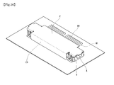
- FIG. 15 in such a configuration where a plug connector X is formed to be smaller in outer shape than a receptacle connector Y so that the fitting of both the connectors X, Y is visible from the above, connection leg portions Y1 of the receptacle connector Y tend to be exposed, and therefore the electromagnetic interference (EMI) is turning into a serious problem along with recent higher-frequency transmission signals.
- a shield cover Z is attached from above so as to cover both the connectors X, Y entirely after fitting, and an end edge portion Z1 of the shield cover Z attached after the connector fitting is extended over the connection leg portions Y1 of the receptacle connector Y to perform electromagnetic shielding.
- the shield cover Z is formed as a separated part, there is the problem that increase in the number of parts and increase in the number of assembling steps due to attachment of the shield cover Z after the fitting of both the connectors X, Y cause reduction in productivity.
- an object of the present invention is to provide an electrical connector with a simple configuration that shields connection leg portions disposed below a signal transmission medium when both connectors are fitted to each other.
- an electronic connector is an electrical connector comprising a connector main body portion provided with a fitting protrusion that is inserted and fitted from above into a fitting recess of another connector mounted on a printed circuit board with connection leg portions joined thereto, a terminal portion of the signal transmission medium being connected to the connector main body portion so as to extend above apart from and substantially in parallel to the printed circuit board, and connection leg portions on a transmission-medium side of the another connector being disposed below the terminal portion of the signal transmission medium connected to the connector main body, wherein the connector main body portion is provided with a transmission-medium-side shield cover extending from between the terminal portion of the signal transmission medium and the connection leg portions on the transmission-medium side of the another connector; and the transmission-medium-side shield cover is extended along the connection leg portions of the transmission-medium side of the another connector so as to cover the connection leg portions on the transmission-medium side of the another connector from above.
- an electronic connector assembly is an electrical connector assembly, where a fitting protrusion provided on a connector main body portion of a first connector is inserted and fitted from above into a fitting recess of a second connector mounted on a printed circuit board with connection leg portions joined thereto, a terminal portion of a signal transmission medium is connected to the connector main body portion of the first connector so as to extend above apart from and substantially in parallel to the printed circuit board, and the connection leg portions on a transmission-medium side of the second connector are disposed below the terminal portion of the signal transmission medium connected to the connector main body, wherein the connector main body portion of the first connector is provided with a transmission-medium-side shield cover extending from between the terminal portion of the signal transmission medium and the connection leg portions on the transmission-medium side of the second connector; and the transmission-medium-side shield cover is extended along the connection leg portions on the transmission-medium side of the second connector so as to cover the connection leg portions on the transmission-medium side of the second connector from
- the transmission-medium-side shield cover that covers the connection leg portions on the transmission-medium side of the another connector (second connector) from above is preliminarily provided on the connector main body portion, the connection leg portions on the transmission-medium side disposed below the signal transmission medium are covered from above with the transmission-medium-side shield cover at a fitting time of both the connectors, so that electromagnetic interference (EMI) can be successfully prevented from occurring.
- EMI electromagnetic interference
- the another connector or the second connector is provided with connection leg portions on an anti-transmission-medium side extending from the connector main body portion in the opposite direction of the connection leg portions on the transmission-medium side, and it is desired that the connector main body portion is provided with an anti-transmission-medium-side shield cover that covers the connection leg portions on the anti-transmission-medium side from above.
- connection leg portions on the anti-transmission-medium side extending in the opposite direction of the terminal portion of the signal transmission medium are covered from above with the anti-transmission-medium-side shield cover when both the connectors are fitted to each other, electromagnetic interference (EMI) can be more successfully prevented from occurring.
- EMI electromagnetic interference
- the transmission-medium-side shield cover and the anti-transmission-medium side shield cover be provided with fitting guide portions that come into contact with an outer surface of the another connector or the second connector in an operation of fitting both the connectors.
- end edge portions of the transmission-medium-side shield cover and the anti-transmission-medium side shield cover be provided with fitting supporting portions that come into contact with or come close to a surface of the printed circuit board when the operation of fitting both the connectors is completed.
- the electrical connector and the assembly thereof since, when external acting force is applied to the connector main body portion via the terminal portion of the signal transmission medium after the connector fitting operation is completed, the fitting supporting portions of the transmission-medium-side shield cover and the anti-transmission-medium side shield cover come into contact with the surface of the printed circuit board and the external acting force is received by the printed circuit board, so that the strength of the connector main body portion against external force is improved and accordingly good stability of electrical connection is maintained.
- the electrical connector and the assembly thereof according to the present invention adopts the configuration that successfully prevents occurrence of electromagnetic interference (EMI) by providing the connector main body portion preliminarily with the transmission-medium-side shield cover extending from between the terminal portion of the signal transmission medium and the connection leg portions on the transmission-medium side of the another connector (second connector), and covering the connection leg portions on the transmission-medium side disposed below the signal transmission medium (thin coaxial cables) from above with the transmission-medium-side shield cover when both the connectors are fitted to each other, the connection leg portions disposed below the signal transmission medium can be electromagnetically shielded with the simple configuration immediately when both the connectors are fitted to each other, so that performance or reliability of the electrical connector can be significantly improved at low cost.
- EMI electromagnetic interference
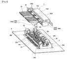
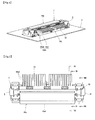
- an electrical connector assembly according to an embodiment of the present invention shown in FIGS. 1 to 8 is constituted by a vertically-fitting type connector composed of a plug connector (first connector) 1 connected to terminal portions of thin coaxial cables SC as signal transmission media and a receptacle connector (second connector) 2 into which the plug connector 1 is fitted from above.
- the receptacle connector 2 included therein is configured to be mounted on a printed circuit board P with connection leg portions joined thereto, and the operation of fitting both the connectors 1, 2 is performed by bringing down the plug connector 1 disposed above the receptacle connector 2 in a downward direction in FIG.
- a direction in which the plug connector 1 is inserted is defined as “downward direction”
- the opposite direction in which the plug connector 1 is drawn out is defined as “upward direction”.
- plug connector (first connector) 1 and receptacle connector (second connector) 2 have connector main body portions 10, 20 formed in an elongated shape.
- a longitudinal direction of the connector main body portions 10, 20 is called “connector longitudinal direction”, and a direction perpendicular to both the connector longitudinal direction and the upward and downward directions described above is called “front-back direction”.
- metal conductive shells 14, 24 also included in the connector main body portions 10, 20 are attached to outer surfaces of the insulating housings 11, 21 described above.
- the conductive shell 14 of the plug connector (first connector) 1 is attached so as to cover almost an entire surface except for a bottom face having the fitting protrusion 1A (see FIGS. 12 and 13 ) described above, while the conductive shell 24 of the receptacle connector (second connector) 2 is attached so as to cover peripheral portions except for an upper face having the fitting recess 2A (see FIGS. 12 and 13 ) described above and a lower face which is a mounting face.
- the fitting protrusion 1A and the fitting recess 2A (see FIGS. 12 and 13 ) of both the connectors 1, 2 described above are obtained by forming the insulating housings 11, 21 and the conductive shells 14, 24 into a protruded shape and a recessed shape extending in the connector longitudinal direction, and in these protruded portions and recessed portions of the insulating housings 11, 21 and the conductive shells 14, 24, the contact portions of the conductive terminals (contacts) 12, 13 and 22, 23 and contact portions of the conductive shells 14, 24 are disposed, so that an electrical and mechanical fitting relationship is formed between both the connectors 1, 2 at the time of fitting.
- the terminal portions of the thin coaxial cables (signal transmission medium) SC are connected to one end edge portion of the plug connector (first connector) 1 in the front-back direction, and the plurality of thin coaxial cables SC are arranged in the connector longitudinal direction so as to form multipolar shape.
- the elongated end edge portion connected to the terminal portions of the thin coaxial cables SC is called “rear-end edge portion”
- the opposite front elongated end edge portion is called “front-end edge portion”.
- respective elongated end edge portions of the receptacle connector 2 that correspond to the "rear-end edge portion” and the “front-end edge portion” of the plug connector 1 are also called “rear-end edge portion” and "front-end edge portion” in the same manner.
- a cable central conductor (signal line) SCa and a cable external conductor (shield line) SCb are exposed by peeling off their cable sheaths.
- the cable central conductors SCa disposed along the axes of the thin coaxial cables SC are collectively soldered to the respective first and second conductive terminals (contacts) 12, 13 of the plug connector (first connector) 1 described above, and signal transmission circuits are formed by connecting the first and second conductive terminals (contacts) 12, 13 of the plug connector (first connector) 1 to the respective first and second conductive terminals (contacts) 22, 23 of the receptacle connector (second connector) 2, as described later.
- the respective conductive terminals (contacts) 12, 13 of the plug connector 1 and the thin coaxial cables SC can also be connected by swaging, crimping, or the like.
- the cable external conductors SCb disposed around an outer periphery of the cable central conductors SCa are collectively soldered so as to be held between a pair of ground bars SCc, SCd disposed one above the other from above and below.
- These ground bars SCc, SCd are electrically connected by contact with the conductive shell 14 of the plug connector 1, as described later.
- the conductive shell 14 attached to the plug connector (first connector) 1 is formed by bending a thin-plate-shaped metal member elongated in the connector longitudinal direction into a suitable shape, and configured to cover the plug connector 1 from above almost entirely except for the fitting protrusion 1A, and to cover the electrical connector assembly including the receptacle connector (second connector) 2 from above almost entirely, as described later, after the fitting operation, so that the conductive shell 14 has a preferred structure in obtaining an electromagnetic shielding effect against electromagnetic interference (EMI).
- EMI electromagnetic interference
- the conductive shell 14 is composed of a front conductive shell 14a covering a front portion of the plug connector (first connector) 1 and a rear conductive shell 14b covering a rear portion of the plug connector 1.
- the front conductive shell 14a has such a shape as shown particularly in FIG. 9 , and is attached to the insulating housing 11 from above by press-fitting. Specifically, the conductive shell 14 is fixed to the insulating housing 11 by engagement of insertion fixing portions 14a1 provided on both end portions of the front conductive shell 14a in the connector longitudinal direction with the insulating housing 11.
- a main shell portion 14a2 constituting a uppermost face portion of the front conductive shell 14a is formed of a substantially flat plate-shaped member extending in the connector longitudinal direction, and a rear-end edge portion of the main shell portion 14a2 is provided with a plurality of ground connection tabs 14a3 disposed at suitable intervals in the connector longitudinal direction.
- the respective ground connection tabs 14a3 are formed by notching, and melting solder is poured into respective notches, thereby soldering the ground connection tabs 14a3 to an upper face of the upper ground bar SCd described above so that a ground circuit is electrically connected.
- a front-end edge portion of the main shell portion 14a2 constituting the front conductive shell 14a of the plug connector (first connector) 1 is formed so as to extend substantially flatly, and the flat front-end edge portion of the main shell portion 14a2 is configured to come into contact from above with a portion of the receptacle connector (second connector) 2, specifically, a front-end protrusion 24d of the conductive shell 24 described later, when the operation of fitting both the connectors 1, 2 is completed, so that the ground circuit is electrically connected between the plug connector 1 and the receptacle connector 2.
- the main shell portion 14a2 constituting the front conductive shell 14a of the plug connector 1 is provided with an anti-transmission-medium-side shield cover 14a4 extending frontward, that is, in the opposite direction of the thin coaxial cables (signal transmission medium) SC described above.
- the anti-transmission-medium-side shield cover 14a4 is a component of an important portion of the present invention and therefore will be described later in detail.
- the rear conductive shell 14b has such a shape as shown particularly in FIG. 10 , and includes an intermediate ground portion 14b1 for so-called crosstalk prevention disposed so as to form an elongated bar in the connector longitudinal direction, a plurality of curved connection pieces 14b2 extending backward from the intermediate ground portion 14b1, and a main shell portion 14b3 connected to rear-end portions of the plurality of curved connection pieces 14b2.
- the main shell portion 14b3 is formed of a substantially-flat plate-shaped member extending in the connector longitudinal direction, and a front end portion of the main shell portion 14b3 is insert-molded to the insulating housing 11 described above along with the intermediate ground portion 14b1 and the curved connection pieces 14b2, thereby fixing the whole of the rear conductive shell 14b.
- a rear end portion of the main shell portion 14b3 constituting the rear conductive shell 14b of the plug connector (first connector) 1 is formed so as to extend horizontally backward from the insulating housing 11, and configured to be disposed so as to contact from below with the lower ground bar SCc described above so that the ground circuit is electrically connected. Note that it is also possible to bring the main shell portion 14b3 in direct contact with the respective cable external conductors SCb of the plurality of thin coaxial cables SC, without using the lower ground bar SCc so that the ground circuit is electrically connected.
- transmission medium restricting plates 14b4 that position the terminal portions of the thin coaxial cables SC are formed so as to rise from both end portions and a central portion of the main shell portion 14b3 in the connector longitudinal direction.
- a rear end portion of the main shell portion 14b3 is provided with a transmission-medium-side shield cover 14b5 extending backward, that is, in the same direction as the thin coaxial cables (signal transmission medium) SC described above, and the transmission-medium-side shield cover 14b5 is a component of an important portion of the present invention, and therefore will be described later in detail.
- the conductive shell 24 provided on the receptacle connector 2 as the second connector described above is disposed so as to extend up to both end edge portions in the connector longitudinal direction along both end portions of the insulating housing 21 in the frontward and backward directions.
- Both end portions of the conductive shell 24 in the connector longitudinal direction are provided with holddowns 24a, 24b formed by bending so as to protrude in the frontward and backward directions, respectively, and holddowns 24c are also formed so as to protrude forward and backward at substantially-central portions of front-end edge portion and rear-end edge portion of the conductive shell 24 in the connector longitudinal direction.
- the conductive shell 24 of the receptacle connector (second connector) 2 described above is provided with a front-end protrusion 24d covering a protruded portion formed at the front-end edge portion of the insulating housing 21 from above.
- the front-end protrusion 24d includes elastic connection tabs 24e protruding obliquely downward toward the fitting recess 2A (see FIGS. 12 and 13 ) described above, and these elastic connection tabs 24e are arranged by plural numbers at suitable intervals in the connector longitudinal direction.
- the respective elastic connection tabs 24e are formed in a cantilever shape by notching so as to have suitable elastic flexibility and configured to come into pressure contact with a front-end wall face of the insulating housing 11 of the plug connector (first connector) 1 described above when the operation of fitting both the connectors 1, 2 is completed.
- first connection leg portions 22a protruding substantially horizontally frontward from the front-end edge portion of the insulating housing 21 are formed at front-end edge portions of one first conductive terminals (contacts) 22 attached to the receptacle connector (second connector) 2, and electrical connection is performed by soldering frontward-protruding portions of the respective first connection leg portions 22a to signal conductive paths (not shown) on the printed circuit board P described above, and thus a signal transmission circuit is configured.
- these first connection leg portions 22a are members corresponding to what are called anti-transmission-medium-side connection leg portions in the present invention, since they protrude in the opposite direction (frontward) of the terminal portions of the thin coaxial cables (signal transmission medium) SC described above.
- second connection leg portions 23a protruding substantially horizontally backward from the rear-end edge portion of the insulating housing 21 are formed at rear-end edge portions of the other second conductive terminals (contacts) 23 attached to the receptacle connector 2, and electrical connection is performed by soldering backward-protruding portions of the respective second connection leg portions 23a to signal conductive paths (not shown) on the printed circuit board P, and thus a signal transmission circuit is configured in the same manner.
- these second connection leg portions 23a are members corresponding to what are called transmission-medium-side connection leg portions in the present invention, since they protrude in the same direction (backward) as the terminal portions of the thin coaxial cables (signal transmission medium) SC described above.
- the terminal portions of the thin coaxial cables SC as signal transmission media are connected to the insulating housing 11 constituting the connector main body portion 10 of the plug connector (first connector) 1, and the terminal portions of the thin coaxial cables SC are positioned above and slightly apart from a surface of the printed circuit board P, and extend backward in substantially parallel with the surface of the printed circuit board P. Further, an arrangement relationship where the second connection leg portions (transmission-medium-side connection leg portions) 23a provided on the second conductive terminals (contacts) 23 of the receptacle connector (second connector) 2 described above extend backward over a suitable distance below the thin coaxial cables (signal transmission medium) SC is adopted.
- the rear conductive shell 14b of the conductive shell 14 provided on the plug connector (first connector) 1 includes the main shell portion 14b3 extending backward in contact with the lower ground bar SCc from below, as described above, and the rear end portion of the main shell portion 14b3 is provided with the transmission-medium-side shield cover 14b5 protruding backward further.
- the transmission-medium-side shield cover 14b5 is disposed below the terminal portions of the thin coaxial cables (signal transmission media) described above, and disposed above the second connection leg portions 23a of the receptacle connector (second connector) 2 so as to extend backward along the second connection leg portions 23a, thereby covering externally-exposed portions of the second connection leg portions 23a from above.
- the transmission-medium-side shield cover 14b5 is extended substantially horizontally from the insulating housing 11 of the plug connector (first connector) 1 and then bent down at a substantially right angle so as to serve as a rear fitting guide portion 14b6.
- the transmission-medium-side shield cover 14b5 is bent again in a substantially-horizontal direction at a substantially right angle from a lower end edge portion of the rear fitting guide portion 14a6 described above, extended backward, and then extended substantially vertically toward the surface of the printed circuit board P so as to bring a distal-end edge portion of the transmission-medium-side shield cover 14b5 close to the surface of the printed circuit board P at the time of fitting both the connectors 1, 2.
- the distal-end edge portion of the transmission-medium-side shield cover 14b5 constitutes a fitting supporting portion 14b7 having a holding action against external force.
- the fitting supporting portion 14b7 provided on the distal-end edge portion of the transmission-medium-side shield cover 14b5 comes into contact with the surface of the printed circuit board P, and accordingly the external acting force is received by the printed circuit board P, and therefore the strength of the whole of the electrical connector assembly against external force is improved so that good stability of electrical connection is maintained.
- fitting supporting portion 14b7 is disposed close to the surface of the printed circuit board P at the time of fitting both the connectors 1, 2, as described above, but an arrangement relationship can be adopted that the fitting supporting portion 14b7 is brought into contact with the surface of the printed circuit board P at that time.
- fitting supporting portion 14b7 provided on the distal-end edge portion of the transmission-medium-side shield cover 14b5 is formed so as to be positioned behind backward-protruding ends of the second connection leg portions 23a, so that the second connection leg portions 23a, including land portions P1 formed on the surface of the printed circuit board P, are covered from above with the transmission-medium-side shield cover 14b5.
- the connector main body portion 10 is preliminarily provided with the transmission-medium-side shield cover 14b5 that covers the second connection leg portions 23a of the receptacle connector (second connector) 2 from above, the second connection leg portions 23a disposed below the terminal portions of the thin coaxial cables (signal transmission media) SC are covered from above with the transmission-medium-side shield cover 14b5 when both the connectors 1, 2 are fitted to each other, so that electromagnetic interference (EMI) is successfully prevented from occurring.
- EMI electromagnetic interference
- the main shell portion 14a2 of the front conductive shell 14a constituting the conductive shell 14 is similarly provided with the anti-transmission-medium-side shield cover 14a4 extending frontward.
- the anti-transmission-medium-side shield cover 14a4 is bent down at a substantially right angle from the front-end edge portion of the main shell portion 14a2 so as to form a front fitting guide portion 14a5.
- the operation of fitting the plug connector 1 into the receptacle connector (second connector) 2 is stably performed. That is, when both the connectors 1, 2 are fitted to each other, positioning in the fitting operation is successfully performed by, first of all, bringing the front fitting guide portion 14a5 of the plug connector 1 into contact with the front-end edge portion of the receptacle connector, for example, as shown in FIG. 12 , pivoting a rear end portion of the plug connector 1 downward in the direction of arrow about the contact edge so as to be in a state shown in FIG.
- the anti-transmission-medium-side shield cover 14b4 is bent again in a substantially-horizontal direction at a substantially right angle from a lower end edge portion of the front fitting guide portion 14a5 described above, extended frontward, and then extended substantially vertically toward the surface of the printed circuit board P so as to bring a distal end edge portion of the anti-transmission-medium-side shield cover 14a4 close to the surface of the printed circuit board P at the time of fitting both the connectors 1, 2.
- the distal end edge portion of the anti-transmission-medium-side shield cover 14a4 constitutes a fitting supporting portion 14a6 having a holding action against external force.
- the fitting supporting portion 14b6 provided on the distal end edge portion of the anti-transmission-medium-side shield cover 14b4 comes into contact with the surface of the printed circuit board P, and accordingly the external acting force is received by the printed circuit board P, and therefore the strength of the whole of the electrical connector assembly against external force is improved so that good stability of electrical connection is maintained.
- fitting supporting portions 14a6, 14b7 according to this embodiment is disposed close to the surface of the printed circuit board P at the time of fitting both the connectors 1, 2, as described above, but such an arrangement relationship can be adopted that the fitting supporting portions 14a6, 14b7 are brought into contact with the surface of the printed circuit board P at that time.
- fitting supporting portion 14a6 provided on the distal end edge portion of the anti-transmission-medium-side shield cover 14a4 is formed so as to be positioned behind frontward-protruding ends of the first connection leg portions 22a, so that the first connection leg portions 22a, including land portions P1 formed on the surface of the printed circuit board P, are covered from above with the anti-transmission-medium-side shield cover 14a4.
- the connector main body portion 10 is preliminarily provided with the anti-transmission-medium-side shield cover 14a4 that covers the first connection leg portions 22a of the receptacle connector (second connector) 2 from above, the first connection leg portions 22a is covered from above with the anti-transmission-medium-side shield cover 14a4 when both the connectors 1, 2 are fitted to each other, so that electromagnetic interference (EMI) is successfully prevented from occurring.
- EMI electromagnetic interference
- conductive terminals (contacts) different in shape from each other are alternately disposed, but the present invention is also similarly applicable to an electrical connector where conductive terminals having the same shape are arranged so as to form a multipolar arrangement.
- the present invention is not limited to such a connector for thin coaxial cables as in the embodiment described above, and is also similarly applicable to an electrical connector of a type in which a plurality of thin coaxial cables and insulating cables coexist, an electrical connector that connects a flexible circuit board or the like, or the like.
- the present invention is widely applicable to various electrical connectors used for electrical devices.
Landscapes
- Details Of Connecting Devices For Male And Female Coupling (AREA)
- Coupling Device And Connection With Printed Circuit (AREA)
Applications Claiming Priority (1)
| Application Number | Priority Date | Filing Date | Title |
|---|---|---|---|
| JP2010237065A JP5594053B2 (ja) | 2010-10-22 | 2010-10-22 | 電気コネクタ及びその組立体 |
Publications (2)
| Publication Number | Publication Date |
|---|---|
| EP2445061A1 true EP2445061A1 (fr) | 2012-04-25 |
| EP2445061B1 EP2445061B1 (fr) | 2016-07-20 |
Family
ID=44674622
Family Applications (1)
| Application Number | Title | Priority Date | Filing Date |
|---|---|---|---|
| EP11183048.5A Not-in-force EP2445061B1 (fr) | 2010-10-22 | 2011-09-28 | Connecteur électrique et ensemble correspondant |
Country Status (6)
| Country | Link |
|---|---|
| US (1) | US8602812B2 (fr) |
| EP (1) | EP2445061B1 (fr) |
| JP (1) | JP5594053B2 (fr) |
| KR (1) | KR101294607B1 (fr) |
| CN (1) | CN102570187B (fr) |
| TW (1) | TWI456850B (fr) |
Cited By (2)
| Publication number | Priority date | Publication date | Assignee | Title |
|---|---|---|---|---|
| FR3035273A1 (fr) * | 2015-04-17 | 2016-10-21 | Dai-Ichi Seiko Co Ltd | Connecteur electrique et dispositif de connecteur electrique |
| CN111628336A (zh) * | 2020-06-24 | 2020-09-04 | 东莞市信翰精密工业有限公司 | 一种屏蔽线束直头连接器 |
Families Citing this family (25)
| Publication number | Priority date | Publication date | Assignee | Title |
|---|---|---|---|---|
| TWM405736U (en) * | 2010-11-30 | 2011-06-21 | Bing Xu Prec Co Ltd | Connector and connector assembly |
| TWM458009U (zh) * | 2012-01-05 | 2013-07-21 | Ant Prec Industry Co Ltd | 電連接器及使用該電連接器之電子裝置 |
| JP5786228B2 (ja) * | 2012-08-08 | 2015-09-30 | ヒロセ電機株式会社 | 電気コネクタ |
| EP2936618A1 (fr) * | 2012-12-19 | 2015-10-28 | 3M Innovative Properties Company | Connecteur câble-carte |
| JP5970400B2 (ja) * | 2013-03-19 | 2016-08-17 | 日本航空電子工業株式会社 | 導電パターン式コネクタ及びコネクタユニット |
| JP6005575B2 (ja) * | 2013-04-11 | 2016-10-12 | 日本航空電子工業株式会社 | コネクタ |
| US9112302B2 (en) * | 2013-05-02 | 2015-08-18 | Hon Hai Precision Industry Co., Ltd. | Electrical connector and assembly thereof |
| JP5747953B2 (ja) * | 2013-06-27 | 2015-07-15 | Smk株式会社 | コネクタ |
| CN203932413U (zh) * | 2013-07-22 | 2014-11-05 | 秉旭精密股份有限公司 | Sata电连接器及电连接器组合 |
| JP6249676B2 (ja) * | 2013-08-21 | 2017-12-20 | 宏致電子股▲ふん▼有限公司Aces Electronics Co.,Ltd. | 電気コネクタ |
| JP5716933B2 (ja) * | 2013-10-04 | 2015-05-13 | 第一精工株式会社 | 配線基板連結装置 |
| JP6056830B2 (ja) * | 2014-10-10 | 2017-01-11 | 第一精工株式会社 | 電気コネクタ及び電気コネクタ装置 |
| JP6052268B2 (ja) * | 2014-11-28 | 2016-12-27 | 第一精工株式会社 | 電気コネクタ及び電気コネクタ装置 |
| JP6741040B2 (ja) * | 2018-05-10 | 2020-08-19 | 第一精工株式会社 | ケーブルコネクタ装置 |
| CN110611221B (zh) * | 2018-06-14 | 2021-02-26 | 鸿富锦精密电子(天津)有限公司 | 锁固结构及采用该锁固结构的线缆接头组件 |
| JP7202937B2 (ja) * | 2018-12-19 | 2023-01-12 | モレックス エルエルシー | コネクタ及びコネクタ組立体 |
| JP6859998B2 (ja) | 2018-12-28 | 2021-04-14 | I−Pex株式会社 | 電気コネクタおよびコネクタ装置 |
| CN111555067B (zh) * | 2020-04-15 | 2022-03-04 | 东莞立讯技术有限公司 | 连接器 |
| KR102304611B1 (ko) * | 2021-01-14 | 2021-09-24 | 협진커넥터(주) | 고주파용 기판 대 기판 커넥터 |
| JP7623212B2 (ja) * | 2021-05-17 | 2025-01-28 | 日本航空電子工業株式会社 | コネクタ組立体 |
| CN113422254B (zh) * | 2021-06-22 | 2022-04-01 | 中航光电科技股份有限公司 | 母端连接器及高速极细同轴连接器组件 |
| TWI850635B (zh) * | 2022-03-11 | 2024-08-01 | 唐虞企業股份有限公司 | 電連接器及其製造方法與上層斜插組立件及其組立方法 |
| CN115149295B (zh) * | 2022-07-01 | 2026-03-31 | 立讯精密工业股份有限公司 | 线缆连接器以及连接器组件 |
| US20250079735A1 (en) * | 2023-09-05 | 2025-03-06 | Foxconn (Kunshan) Computer Connector Co., Ltd. | Electrical connector assembly with improved mating interfaces |
| WO2026019018A1 (fr) * | 2024-07-19 | 2026-01-22 | 삼성전자주식회사 | Connecteur et dispositif électronique comprenant ce dernier |
Citations (8)
| Publication number | Priority date | Publication date | Assignee | Title |
|---|---|---|---|---|
| JP2005116447A (ja) * | 2003-10-10 | 2005-04-28 | Sony Corp | コネクタおよび電子機器 |
| JP2005339985A (ja) * | 2004-05-27 | 2005-12-08 | Kel Corp | コネクタ |
| JP3118719U (ja) | 2004-12-28 | 2006-02-02 | 鴻海精密工業股▲ふん▼有限公司 | ケーブル用コネクタ装置 |
| EP1801918A2 (fr) * | 2005-12-21 | 2007-06-27 | Hosiden Corporation | Connecteur et dispositif électronique doté de celui-ci |
| JP2008166094A (ja) * | 2006-12-28 | 2008-07-17 | Hosiden Corp | コネクタ |
| JP2009004117A (ja) | 2007-06-19 | 2009-01-08 | Smk Corp | 多極コネクタ |
| US20100055984A1 (en) * | 2008-09-01 | 2010-03-04 | Masahiro Tsuchida | Connector device |
| JP2010160976A (ja) | 2009-01-08 | 2010-07-22 | I-Pex Co Ltd | コネクタ装置 |
Family Cites Families (9)
| Publication number | Priority date | Publication date | Assignee | Title |
|---|---|---|---|---|
| JP2002170640A (ja) * | 2000-11-29 | 2002-06-14 | Sumitomo Wiring Syst Ltd | コネクタ |
| JP2004247086A (ja) * | 2003-02-12 | 2004-09-02 | Sumitomo Wiring Syst Ltd | 垂直嵌合型コネクタ |
| JP2005122995A (ja) * | 2003-10-15 | 2005-05-12 | Jst Mfg Co Ltd | コネクタ |
| JP4889243B2 (ja) * | 2005-06-09 | 2012-03-07 | モレックス インコーポレイテド | コネクタ装置 |
| JP4175657B2 (ja) * | 2006-01-17 | 2008-11-05 | 日本航空電子工業株式会社 | コネクタ |
| JP5110271B2 (ja) * | 2007-08-22 | 2012-12-26 | 第一精工株式会社 | コネクタ装置 |
| US7883364B2 (en) * | 2008-12-09 | 2011-02-08 | Hon Hai Precision Ind. Co., Ltd. | Cable assembly having shroud substantially covering mated receptacle connector |
| JP2010157367A (ja) * | 2008-12-26 | 2010-07-15 | Jst Mfg Co Ltd | 電気コネクタ |
| TWM371317U (en) * | 2009-08-10 | 2009-12-21 | Ant Prec Industry Co Ltd | SATA electrical connector and assembly thereof |
-
2010
- 2010-10-22 JP JP2010237065A patent/JP5594053B2/ja not_active Expired - Fee Related
-
2011
- 2011-09-23 US US13/243,111 patent/US8602812B2/en not_active Expired - Fee Related
- 2011-09-28 EP EP11183048.5A patent/EP2445061B1/fr not_active Not-in-force
- 2011-10-17 TW TW100137480A patent/TWI456850B/zh not_active IP Right Cessation
- 2011-10-20 KR KR1020110107302A patent/KR101294607B1/ko not_active Expired - Fee Related
- 2011-10-21 CN CN201110322401.5A patent/CN102570187B/zh not_active Expired - Fee Related
Patent Citations (8)
| Publication number | Priority date | Publication date | Assignee | Title |
|---|---|---|---|---|
| JP2005116447A (ja) * | 2003-10-10 | 2005-04-28 | Sony Corp | コネクタおよび電子機器 |
| JP2005339985A (ja) * | 2004-05-27 | 2005-12-08 | Kel Corp | コネクタ |
| JP3118719U (ja) | 2004-12-28 | 2006-02-02 | 鴻海精密工業股▲ふん▼有限公司 | ケーブル用コネクタ装置 |
| EP1801918A2 (fr) * | 2005-12-21 | 2007-06-27 | Hosiden Corporation | Connecteur et dispositif électronique doté de celui-ci |
| JP2008166094A (ja) * | 2006-12-28 | 2008-07-17 | Hosiden Corp | コネクタ |
| JP2009004117A (ja) | 2007-06-19 | 2009-01-08 | Smk Corp | 多極コネクタ |
| US20100055984A1 (en) * | 2008-09-01 | 2010-03-04 | Masahiro Tsuchida | Connector device |
| JP2010160976A (ja) | 2009-01-08 | 2010-07-22 | I-Pex Co Ltd | コネクタ装置 |
Cited By (2)
| Publication number | Priority date | Publication date | Assignee | Title |
|---|---|---|---|---|
| FR3035273A1 (fr) * | 2015-04-17 | 2016-10-21 | Dai-Ichi Seiko Co Ltd | Connecteur electrique et dispositif de connecteur electrique |
| CN111628336A (zh) * | 2020-06-24 | 2020-09-04 | 东莞市信翰精密工业有限公司 | 一种屏蔽线束直头连接器 |
Also Published As
| Publication number | Publication date |
|---|---|
| KR20120042662A (ko) | 2012-05-03 |
| JP2012089435A (ja) | 2012-05-10 |
| JP5594053B2 (ja) | 2014-09-24 |
| KR101294607B1 (ko) | 2013-08-08 |
| EP2445061B1 (fr) | 2016-07-20 |
| CN102570187B (zh) | 2014-12-31 |
| US8602812B2 (en) | 2013-12-10 |
| TWI456850B (zh) | 2014-10-11 |
| TW201251237A (en) | 2012-12-16 |
| US20120100743A1 (en) | 2012-04-26 |
| CN102570187A (zh) | 2012-07-11 |
Similar Documents
| Publication | Publication Date | Title |
|---|---|---|
| EP2445061B1 (fr) | Connecteur électrique et ensemble correspondant | |
| EP2789056B1 (fr) | Connecteur d'embase pour cable | |
| US6582252B1 (en) | Termination connector assembly with tight angle for shielded cable | |
| EP3591767B1 (fr) | Faisceau de câbles comprenant une pluralite de cables de signal | |
| US9806475B2 (en) | Waterproof electrical connector | |
| US8888533B2 (en) | Cable header connector | |
| EP2333910B1 (fr) | Fiche multipolaire | |
| US8021187B2 (en) | Electric connector | |
| US7465186B2 (en) | Electric connector | |
| US9595793B2 (en) | Electric connector having a retaining member with a cover in electrical contact with a shell of a mating connector | |
| EP2330693B1 (fr) | Connecteur électrique | |
| EP2770588A1 (fr) | Structures de mise à la terre pour modules de contact d'ensembles connecteurs | |
| EP1017134A2 (fr) | Connecteur à grande fréquence et méthode de sa fabrication | |
| JP4900707B2 (ja) | 電気コネクタ及びその製造方法 | |
| US10868392B2 (en) | Ground commoning conductors for electrical connector assemblies | |
| JP5315912B2 (ja) | 多連装電気コネクタ | |
| US12300957B2 (en) | Contact assembly for a cable card assembly of an electrical connector | |
| JP5338261B2 (ja) | 電気コネクタ | |
| JP2022171889A (ja) | 電気コネクタ | |
| CN112655119A (zh) | 具有阴阳同体的端子和壳体的电连接器 | |
| US20240347982A1 (en) | Cable card assembly of an electrical connector having capacitors | |
| CN118712821A (zh) | 用于电连接器组件的片式组件的电屏蔽 | |
| US12580332B2 (en) | Ground bus for a cable card assembly of an electrical connector | |
| US20250266628A1 (en) | Cable card assembly of an electrical connector | |
| EP0739061A1 (fr) | Connecteur à angle droit avec embout séparé |
Legal Events
| Date | Code | Title | Description |
|---|---|---|---|
| AK | Designated contracting states |
Kind code of ref document: A1 Designated state(s): AL AT BE BG CH CY CZ DE DK EE ES FI FR GB GR HR HU IE IS IT LI LT LU LV MC MK MT NL NO PL PT RO RS SE SI SK SM TR |
|
| AX | Request for extension of the european patent |
Extension state: BA ME |
|
| PUAI | Public reference made under article 153(3) epc to a published international application that has entered the european phase |
Free format text: ORIGINAL CODE: 0009012 |
|
| 17P | Request for examination filed |
Effective date: 20121025 |
|
| 17Q | First examination report despatched |
Effective date: 20140723 |
|
| REG | Reference to a national code |
Ref country code: DE Ref legal event code: R079 Ref document number: 602011028282 Country of ref document: DE Free format text: PREVIOUS MAIN CLASS: H01R0013658100 Ipc: H01R0012790000 |
|
| GRAP | Despatch of communication of intention to grant a patent |
Free format text: ORIGINAL CODE: EPIDOSNIGR1 |
|
| RIC1 | Information provided on ipc code assigned before grant |
Ipc: H01R 12/71 20110101ALN20160105BHEP Ipc: H01R 12/77 20110101ALI20160105BHEP Ipc: H01R 12/79 20110101AFI20160105BHEP Ipc: H01R 13/6581 20110101ALI20160105BHEP Ipc: H01R 12/59 20110101ALI20160105BHEP |
|
| INTG | Intention to grant announced |
Effective date: 20160208 |
|
| GRAS | Grant fee paid |
Free format text: ORIGINAL CODE: EPIDOSNIGR3 |
|
| GRAA | (expected) grant |
Free format text: ORIGINAL CODE: 0009210 |
|
| AK | Designated contracting states |
Kind code of ref document: B1 Designated state(s): AL AT BE BG CH CY CZ DE DK EE ES FI FR GB GR HR HU IE IS IT LI LT LU LV MC MK MT NL NO PL PT RO RS SE SI SK SM TR |
|
| REG | Reference to a national code |
Ref country code: GB Ref legal event code: FG4D |
|
| REG | Reference to a national code |
Ref country code: CH Ref legal event code: EP |
|
| REG | Reference to a national code |
Ref country code: IE Ref legal event code: FG4D |
|
| REG | Reference to a national code |
Ref country code: AT Ref legal event code: REF Ref document number: 814748 Country of ref document: AT Kind code of ref document: T Effective date: 20160815 |
|
| REG | Reference to a national code |
Ref country code: DE Ref legal event code: R096 Ref document number: 602011028282 Country of ref document: DE |
|
| REG | Reference to a national code |
Ref country code: FR Ref legal event code: PLFP Year of fee payment: 6 |
|
| REG | Reference to a national code |
Ref country code: NL Ref legal event code: FP |
|
| REG | Reference to a national code |
Ref country code: LT Ref legal event code: MG4D |
|
| REG | Reference to a national code |
Ref country code: AT Ref legal event code: MK05 Ref document number: 814748 Country of ref document: AT Kind code of ref document: T Effective date: 20160720 |
|
| PG25 | Lapsed in a contracting state [announced via postgrant information from national office to epo] |
Ref country code: IT Free format text: LAPSE BECAUSE OF FAILURE TO SUBMIT A TRANSLATION OF THE DESCRIPTION OR TO PAY THE FEE WITHIN THE PRESCRIBED TIME-LIMIT Effective date: 20160720 Ref country code: FI Free format text: LAPSE BECAUSE OF FAILURE TO SUBMIT A TRANSLATION OF THE DESCRIPTION OR TO PAY THE FEE WITHIN THE PRESCRIBED TIME-LIMIT Effective date: 20160720 Ref country code: LT Free format text: LAPSE BECAUSE OF FAILURE TO SUBMIT A TRANSLATION OF THE DESCRIPTION OR TO PAY THE FEE WITHIN THE PRESCRIBED TIME-LIMIT Effective date: 20160720 Ref country code: RS Free format text: LAPSE BECAUSE OF FAILURE TO SUBMIT A TRANSLATION OF THE DESCRIPTION OR TO PAY THE FEE WITHIN THE PRESCRIBED TIME-LIMIT Effective date: 20160720 Ref country code: NO Free format text: LAPSE BECAUSE OF FAILURE TO SUBMIT A TRANSLATION OF THE DESCRIPTION OR TO PAY THE FEE WITHIN THE PRESCRIBED TIME-LIMIT Effective date: 20161020 Ref country code: IS Free format text: LAPSE BECAUSE OF FAILURE TO SUBMIT A TRANSLATION OF THE DESCRIPTION OR TO PAY THE FEE WITHIN THE PRESCRIBED TIME-LIMIT Effective date: 20161120 Ref country code: HR Free format text: LAPSE BECAUSE OF FAILURE TO SUBMIT A TRANSLATION OF THE DESCRIPTION OR TO PAY THE FEE WITHIN THE PRESCRIBED TIME-LIMIT Effective date: 20160720 |
|
| PG25 | Lapsed in a contracting state [announced via postgrant information from national office to epo] |
Ref country code: SE Free format text: LAPSE BECAUSE OF FAILURE TO SUBMIT A TRANSLATION OF THE DESCRIPTION OR TO PAY THE FEE WITHIN THE PRESCRIBED TIME-LIMIT Effective date: 20160720 Ref country code: PT Free format text: LAPSE BECAUSE OF FAILURE TO SUBMIT A TRANSLATION OF THE DESCRIPTION OR TO PAY THE FEE WITHIN THE PRESCRIBED TIME-LIMIT Effective date: 20161121 Ref country code: ES Free format text: LAPSE BECAUSE OF FAILURE TO SUBMIT A TRANSLATION OF THE DESCRIPTION OR TO PAY THE FEE WITHIN THE PRESCRIBED TIME-LIMIT Effective date: 20160720 Ref country code: PL Free format text: LAPSE BECAUSE OF FAILURE TO SUBMIT A TRANSLATION OF THE DESCRIPTION OR TO PAY THE FEE WITHIN THE PRESCRIBED TIME-LIMIT Effective date: 20160720 Ref country code: LV Free format text: LAPSE BECAUSE OF FAILURE TO SUBMIT A TRANSLATION OF THE DESCRIPTION OR TO PAY THE FEE WITHIN THE PRESCRIBED TIME-LIMIT Effective date: 20160720 Ref country code: GR Free format text: LAPSE BECAUSE OF FAILURE TO SUBMIT A TRANSLATION OF THE DESCRIPTION OR TO PAY THE FEE WITHIN THE PRESCRIBED TIME-LIMIT Effective date: 20161021 Ref country code: AT Free format text: LAPSE BECAUSE OF FAILURE TO SUBMIT A TRANSLATION OF THE DESCRIPTION OR TO PAY THE FEE WITHIN THE PRESCRIBED TIME-LIMIT Effective date: 20160720 Ref country code: BE Free format text: LAPSE BECAUSE OF NON-PAYMENT OF DUE FEES Effective date: 20160720 |
|
| REG | Reference to a national code |
Ref country code: DE Ref legal event code: R097 Ref document number: 602011028282 Country of ref document: DE |
|
| PG25 | Lapsed in a contracting state [announced via postgrant information from national office to epo] |
Ref country code: EE Free format text: LAPSE BECAUSE OF FAILURE TO SUBMIT A TRANSLATION OF THE DESCRIPTION OR TO PAY THE FEE WITHIN THE PRESCRIBED TIME-LIMIT Effective date: 20160720 Ref country code: RO Free format text: LAPSE BECAUSE OF FAILURE TO SUBMIT A TRANSLATION OF THE DESCRIPTION OR TO PAY THE FEE WITHIN THE PRESCRIBED TIME-LIMIT Effective date: 20160720 Ref country code: MC Free format text: LAPSE BECAUSE OF FAILURE TO SUBMIT A TRANSLATION OF THE DESCRIPTION OR TO PAY THE FEE WITHIN THE PRESCRIBED TIME-LIMIT Effective date: 20160720 |
|
| REG | Reference to a national code |
Ref country code: CH Ref legal event code: PL Ref country code: FR Ref legal event code: PLFP Year of fee payment: 7 |
|
| PLBE | No opposition filed within time limit |
Free format text: ORIGINAL CODE: 0009261 |
|
| STAA | Information on the status of an ep patent application or granted ep patent |
Free format text: STATUS: NO OPPOSITION FILED WITHIN TIME LIMIT |
|
| PG25 | Lapsed in a contracting state [announced via postgrant information from national office to epo] |
Ref country code: DK Free format text: LAPSE BECAUSE OF FAILURE TO SUBMIT A TRANSLATION OF THE DESCRIPTION OR TO PAY THE FEE WITHIN THE PRESCRIBED TIME-LIMIT Effective date: 20160720 Ref country code: CZ Free format text: LAPSE BECAUSE OF FAILURE TO SUBMIT A TRANSLATION OF THE DESCRIPTION OR TO PAY THE FEE WITHIN THE PRESCRIBED TIME-LIMIT Effective date: 20160720 Ref country code: SK Free format text: LAPSE BECAUSE OF FAILURE TO SUBMIT A TRANSLATION OF THE DESCRIPTION OR TO PAY THE FEE WITHIN THE PRESCRIBED TIME-LIMIT Effective date: 20160720 Ref country code: SM Free format text: LAPSE BECAUSE OF FAILURE TO SUBMIT A TRANSLATION OF THE DESCRIPTION OR TO PAY THE FEE WITHIN THE PRESCRIBED TIME-LIMIT Effective date: 20160720 Ref country code: BG Free format text: LAPSE BECAUSE OF FAILURE TO SUBMIT A TRANSLATION OF THE DESCRIPTION OR TO PAY THE FEE WITHIN THE PRESCRIBED TIME-LIMIT Effective date: 20161020 |
|
| 26N | No opposition filed |
Effective date: 20170421 |
|
| GBPC | Gb: european patent ceased through non-payment of renewal fee |
Effective date: 20161020 |
|
| REG | Reference to a national code |
Ref country code: IE Ref legal event code: MM4A |
|
| PG25 | Lapsed in a contracting state [announced via postgrant information from national office to epo] |
Ref country code: CH Free format text: LAPSE BECAUSE OF NON-PAYMENT OF DUE FEES Effective date: 20160930 Ref country code: IE Free format text: LAPSE BECAUSE OF NON-PAYMENT OF DUE FEES Effective date: 20160928 Ref country code: LI Free format text: LAPSE BECAUSE OF NON-PAYMENT OF DUE FEES Effective date: 20160930 Ref country code: GB Free format text: LAPSE BECAUSE OF NON-PAYMENT OF DUE FEES Effective date: 20161020 |
|
| PG25 | Lapsed in a contracting state [announced via postgrant information from national office to epo] |
Ref country code: LU Free format text: LAPSE BECAUSE OF NON-PAYMENT OF DUE FEES Effective date: 20160928 Ref country code: SI Free format text: LAPSE BECAUSE OF FAILURE TO SUBMIT A TRANSLATION OF THE DESCRIPTION OR TO PAY THE FEE WITHIN THE PRESCRIBED TIME-LIMIT Effective date: 20160720 |
|
| PG25 | Lapsed in a contracting state [announced via postgrant information from national office to epo] |
Ref country code: HU Free format text: LAPSE BECAUSE OF FAILURE TO SUBMIT A TRANSLATION OF THE DESCRIPTION OR TO PAY THE FEE WITHIN THE PRESCRIBED TIME-LIMIT; INVALID AB INITIO Effective date: 20110928 Ref country code: CY Free format text: LAPSE BECAUSE OF FAILURE TO SUBMIT A TRANSLATION OF THE DESCRIPTION OR TO PAY THE FEE WITHIN THE PRESCRIBED TIME-LIMIT Effective date: 20160720 |
|
| PG25 | Lapsed in a contracting state [announced via postgrant information from national office to epo] |
Ref country code: MT Free format text: LAPSE BECAUSE OF NON-PAYMENT OF DUE FEES Effective date: 20160930 Ref country code: TR Free format text: LAPSE BECAUSE OF FAILURE TO SUBMIT A TRANSLATION OF THE DESCRIPTION OR TO PAY THE FEE WITHIN THE PRESCRIBED TIME-LIMIT Effective date: 20160720 Ref country code: MK Free format text: LAPSE BECAUSE OF FAILURE TO SUBMIT A TRANSLATION OF THE DESCRIPTION OR TO PAY THE FEE WITHIN THE PRESCRIBED TIME-LIMIT Effective date: 20160720 |
|
| REG | Reference to a national code |
Ref country code: FR Ref legal event code: PLFP Year of fee payment: 8 |
|
| PG25 | Lapsed in a contracting state [announced via postgrant information from national office to epo] |
Ref country code: AL Free format text: LAPSE BECAUSE OF FAILURE TO SUBMIT A TRANSLATION OF THE DESCRIPTION OR TO PAY THE FEE WITHIN THE PRESCRIBED TIME-LIMIT Effective date: 20160720 |
|
| PGFP | Annual fee paid to national office [announced via postgrant information from national office to epo] |
Ref country code: FR Payment date: 20180925 Year of fee payment: 8 Ref country code: DE Payment date: 20180920 Year of fee payment: 8 |
|
| PGFP | Annual fee paid to national office [announced via postgrant information from national office to epo] |
Ref country code: NL Payment date: 20180919 Year of fee payment: 8 |
|
| REG | Reference to a national code |
Ref country code: DE Ref legal event code: R119 Ref document number: 602011028282 Country of ref document: DE |
|
| REG | Reference to a national code |
Ref country code: NL Ref legal event code: MM Effective date: 20191001 |
|
| PG25 | Lapsed in a contracting state [announced via postgrant information from national office to epo] |
Ref country code: NL Free format text: LAPSE BECAUSE OF NON-PAYMENT OF DUE FEES Effective date: 20191001 Ref country code: DE Free format text: LAPSE BECAUSE OF NON-PAYMENT OF DUE FEES Effective date: 20200401 |
|
| PG25 | Lapsed in a contracting state [announced via postgrant information from national office to epo] |
Ref country code: FR Free format text: LAPSE BECAUSE OF NON-PAYMENT OF DUE FEES Effective date: 20190930 |