EP2445319A2 - Procédé et dispositif destinés à la définition d'au moins un paramètre de variation de lumière pour une lampe à décharge à haute pression (HID) raccordée à un appareil de fonctionnement multilampes et dotée d'une puissance nominale prédéterminée - Google Patents
Procédé et dispositif destinés à la définition d'au moins un paramètre de variation de lumière pour une lampe à décharge à haute pression (HID) raccordée à un appareil de fonctionnement multilampes et dotée d'une puissance nominale prédéterminée Download PDFInfo
- Publication number
- EP2445319A2 EP2445319A2 EP11186483A EP11186483A EP2445319A2 EP 2445319 A2 EP2445319 A2 EP 2445319A2 EP 11186483 A EP11186483 A EP 11186483A EP 11186483 A EP11186483 A EP 11186483A EP 2445319 A2 EP2445319 A2 EP 2445319A2
- Authority
- EP
- European Patent Office
- Prior art keywords
- lamp
- determined
- dimming
- power
- voltage
- Prior art date
- Legal status (The legal status is an assumption and is not a legal conclusion. Google has not performed a legal analysis and makes no representation as to the accuracy of the status listed.)
- Withdrawn
Links
Images


Classifications
-
- H—ELECTRICITY
- H05—ELECTRIC TECHNIQUES NOT OTHERWISE PROVIDED FOR
- H05B—ELECTRIC HEATING; ELECTRIC LIGHT SOURCES NOT OTHERWISE PROVIDED FOR; CIRCUIT ARRANGEMENTS FOR ELECTRIC LIGHT SOURCES, IN GENERAL
- H05B41/00—Circuit arrangements or apparatus for igniting or operating discharge lamps
- H05B41/14—Circuit arrangements
- H05B41/26—Circuit arrangements in which the lamp is fed by power derived from DC by means of a converter, e.g. by high-voltage DC
- H05B41/28—Circuit arrangements in which the lamp is fed by power derived from DC by means of a converter, e.g. by high-voltage DC using static converters
- H05B41/288—Circuit arrangements in which the lamp is fed by power derived from DC by means of a converter, e.g. by high-voltage DC using static converters with semiconductor devices and specially adapted for lamps without preheating electrodes, e.g. for high-intensity discharge lamps, high-pressure mercury or sodium lamps or low-pressure sodium lamps
- H05B41/2885—Static converters especially adapted therefor; Control thereof
- H05B41/2887—Static converters especially adapted therefor; Control thereof characterised by a controllable bridge in the final stage
-
- H—ELECTRICITY
- H05—ELECTRIC TECHNIQUES NOT OTHERWISE PROVIDED FOR
- H05B—ELECTRIC HEATING; ELECTRIC LIGHT SOURCES NOT OTHERWISE PROVIDED FOR; CIRCUIT ARRANGEMENTS FOR ELECTRIC LIGHT SOURCES, IN GENERAL
- H05B41/00—Circuit arrangements or apparatus for igniting or operating discharge lamps
- H05B41/14—Circuit arrangements
- H05B41/36—Controlling
-
- H—ELECTRICITY
- H05—ELECTRIC TECHNIQUES NOT OTHERWISE PROVIDED FOR
- H05B—ELECTRIC HEATING; ELECTRIC LIGHT SOURCES NOT OTHERWISE PROVIDED FOR; CIRCUIT ARRANGEMENTS FOR ELECTRIC LIGHT SOURCES, IN GENERAL
- H05B41/00—Circuit arrangements or apparatus for igniting or operating discharge lamps
- H05B41/14—Circuit arrangements
- H05B41/36—Controlling
- H05B41/38—Controlling the intensity of light
- H05B41/382—Controlling the intensity of light during the transitional start-up phase
-
- Y—GENERAL TAGGING OF NEW TECHNOLOGICAL DEVELOPMENTS; GENERAL TAGGING OF CROSS-SECTIONAL TECHNOLOGIES SPANNING OVER SEVERAL SECTIONS OF THE IPC; TECHNICAL SUBJECTS COVERED BY FORMER USPC CROSS-REFERENCE ART COLLECTIONS [XRACs] AND DIGESTS
- Y02—TECHNOLOGIES OR APPLICATIONS FOR MITIGATION OR ADAPTATION AGAINST CLIMATE CHANGE
- Y02B—CLIMATE CHANGE MITIGATION TECHNOLOGIES RELATED TO BUILDINGS, e.g. HOUSING, HOUSE APPLIANCES OR RELATED END-USER APPLICATIONS
- Y02B20/00—Energy efficient lighting technologies, e.g. halogen lamps or gas discharge lamps
Definitions
- the invention relates to a method for setting at least one dimming parameter for a high-pressure (HID) discharge lamp with a predefined rated output, which is connected to a multi-lamp operating device. Moreover, the invention relates to a multi-lamp operating device for carrying out such a method.
- HID high-pressure
- the next higher rated power is set from the ensemble of the lamps to be differentiated and, in turn, it is determined whether the voltage / current characteristic has a positive slope at the set operating point.
- the present invention has the object, when operating a high-pressure discharge lamp from an ensemble of different discharge lamps with respect to their type, but with the same nominal power to detect at least one, the respective lamp associated dimming parameters, so that the lamp then operated with its associated dimming parameters can be.
- the method according to the invention is characterized by the fact that, after the lamp has been ignited, it is initially operated stably at the predetermined rated power and the lamp voltage is detected at this first operating point Subsequently, at least one further operating point with a further lamp power is set, which is smaller than the rated power, and wherein after stationary reaching the further operating point again the lamp voltage is detected and at least a single difference of measured lamp voltages is determined, the lamp type of the lamp in Dependence of the determined, determined at least one voltage difference and the at least one dimming parameter as a function of the determined lamp type of the lamp, respectively defined as a function of at least one voltage difference and the operation of the lamp is based.
- the inventive method is particularly suitable for operation of a dimmable high-pressure discharge lamp on a multi-lamp operating device, said lamp having a predetermined rated power such as 150 watts and the lamp may be in particular a metal halide vapor lamp or a high-pressure sodium lamp.
- the respective type of HID lamp is automatically detected, so that the multi-lamp operating device can operate the recognized lamp with its associated dimming parameters, without the user beyond arranging the lamp for feeding through the multi-lamp operating device out any further action to operate the lamp optimally with its specific dimming parameters.
- stable operation of the lamp at an operating point denotes the achievement of a static or stationary operating point, which is characterized in that the lamp voltage no longer changes when the lamp current is set, and thus the said operating point with predetermined lamp power how the lamp power is reached.
- the second operating point with respect to the lamp power is then adjusted according to the invention, so that this second operating point is "approached” in a dynamic operating phase, at which the lamp voltage at the then achieved lamp power no longer changes.
- detecting or “detecting” the lamp voltage generally refer to the determinations of this parameter.
- the process can be performed solely by measuring, but for example also by a measurement and a subsequent calculation or any other kind of determination.
- the individual steps of the method according to the invention do not have to follow one another without a time delay; instead, there may also be a time interval between successively executed method steps.
- the lamp may first be ignited and then operated stably at its nominal power until a command for dimming the lamp takes place, for example, a corresponding signal is received or detected by a control device. Previously, the lamp voltage may have been detected at this operating point.
- the method according to the invention is continued and terminated only after receipt of the dimming command, so that the lamp can be operated with its associated dimming parameter upon completion of the method.
- the at least one dimming parameter-dependent dimming parameter is read from a memory of the operating device.
- a predetermined table is stored in this memory, with which values of lamp voltage differences are assigned values of dimming parameters.
- the respectively assigned dimming parameter can then be determined and determined for the operation of the lamp.
- the determination of the type of lamp of the connected lamp is insofar as equating the determination of the respective lamp associated dimming parameter.
- the dimming range of the lamp is determined by the at least one dimming parameter.
- This dimming range can be e.g. determine the power range of the lamp within which the lamp is operable based on its nominal power.
- the discharge lamp of the same rated power that can be operated on the one multi-lamp operating device can be both metal halide vapor lamps and high-pressure sodium lamps.
- both lamps of different types of lamps are usually operated within different dimming ranges in order to avoid a reduced operating time of the respective lighting means. In this way it can be ensured that the respective HID lamp is operated in the power range permitted for this lamp.
- a conventional metal-halide vapor lamp has a dimming range of 100% to 50% of the nominal lamp power, while in the case of a sodium high-pressure lamp, this range is usually between 100% and 30% of the specified nominal power.
- the number of different types of HID bulbs is small as in the present case, it may be sufficient to drive only two such operating points of different lamp power and on the basis of the determined lamp voltages by comparison with stored values, in particular threshold values of lamp differential voltages to determine the type of lamp and thus the dimming parameters.
- a plurality of difference values of the lamp voltages detected at the set operating points can be determined to determine the type of lamp or of the at least one dimming parameter of the lamp and these difference values can each be compared with one or more predetermined threshold values.
- a specification of (n-1) threshold values may be expedient in order to carry out the desired differentiation within the ensemble of dimmable lamps with the same nominal power but different light sources and thus different dimming parameters.
- the entire dimming characteristic of the determined type of light-emitting device in the lamp is determined by the at least one dimming parameter, so that this lamp can then be operated with its specific dimming characteristic.
- the indication of the respective operating parameters of the lamp for setting a predetermined luminous level include.
- the or after the operating point with rated power started further operating points.mit lower lamp power can be selected in particular with respect to their performance with equidistant performance difference of 10 - 20%, in particular 15%.
- the determined dimming parameter of the HID lamp is transmitted via an associated communication interface to a central control device of an illumination system, so that the central control device has all control-relevant information.
- the invention solves the above technical problem with a multi-lamp operating device for operating high-pressure (HID) discharge lamps of a given nominal power and for detecting at least one dimming parameter for the lamp, with an ignition device and an inverter for feeding the connected high pressure (HID ) Discharge lamp and a control device which drives the inverter.
- HID high-pressure
- a control device which drives the inverter.
- the multi-lamp operating device is characterized in that the control device is programmed so that after the ignition of the lamp, first a first operating point at the predetermined nominal power is set, at which the lamp voltage can be detected, wherein subsequently at least one further operating point with another Lamp power is set, which is smaller than the predetermined rated power, in turn, after reaching the other operating point, the lamp voltage is detected and at least a difference of measured lamp voltages can be determined, and wherein the lamp type of the lamp depending on the determined, determines at least one voltage difference and the at least one dimming parameter is set as a function of the determined type of lamp of the lamp.
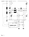
- FIG. 1 schematically shows a multi-lamp operating device for operating dimmable high pressure (HID) discharge lamps of a fixed, predetermined nominal power, with which the inventive method can be carried out to set at least one dimming parameter for the lamp inserted in the operating device, which consists of an ensemble of lamps is selected, which all have the same rated power.
- the operating device is formed in the illustrated embodiment as a half-bridge with two controllable switches S1, S2 of an inverter, which is fed by a DC voltage Vbus.
- This DC voltage Vbus can be taken from a DC voltage source or alternatively from a rectified Netzspahnungsario.
- the typically formed as a semiconductor switch such as a field effect transistor switches S1, S2 are driven by a control unit CU to open and close.
- the half-bridge feeds a high-pressure discharge lamp Lp1 with a rated power of 150 watts across the half-bridge capacitors.
- the lamp may in the described embodiment be either a metal-halogen lamp or a sodium-vapor lamp of said rated power of 150 watts.
- Such high-pressure discharge lamps in contrast to low-pressure gas discharge lamps, require a comparatively high ignition voltage; moreover, they have a high luminance, which is why they are frequently used for illumination in outdoor areas.
- FIG. 1 illustrated exemplary circuitry on an ignition circuit part, which comprises a surge capacitor C3, which is charged via the resistor R1 from the DC voltage Vbus.
- the ignition circuit part further comprises the primary-side part L3b of a transformer L3b of a transformer L3b / L3a and a switch S3, which is also controlled by the control device CU.
- the switch S3 By closing the switch S3, the capacitor C3 discharges, so that a primary-side ignition pulse is generated, which is transmitted with a corresponding transmission ratio to the lamp Lp1 to provide the necessary breakdown voltage in the lamp.
- the half-bridge inverter further comprises the two inductors L1, L2 and the smoothing capacitors C1, C2, C4 and C5.
- the operating device detects the potentials at the electrodes of the lamp and thus the lamp voltage Ui as the difference of both potentials.
- the two lamp potentials are located at the associated inputs of the control device CU on. Also indicated schematically in the figure on the device side is the means for detecting the lamp current, an associated signal being applied to the input I of the control device CU.
- the actuation of the switches S1, S2 takes place in the described embodiment with the aid of a pulse-width-modulated control signal, which is output by the control device CU at its outputs G1, G2.
- the duty cycle of the pulse-width-modulated signal can be used to set the electrical power delivered to the lamp, starting from the rated power and depending on a predetermined dimming value.
- the half-bridge operates as a current source for the lamp, wherein the power supplied to the lamp is controlled or regulated taking into account the detected lamp voltage or the detected lamp current.
- an adjustable power is controlled, the current acting as a setpoint ⁇ e and measuring only the resulting lamp voltage.
- the multi-lamp operating device instead of a half-bridge may also have a full bridge.
- a series resonant circuit may also be provided as the ignition arrangement, comprising at least one inductance and a capacitance in which the lamp is arranged.
- FIG. 2 shows the course of lamp current and lamp voltage for a metal halide vapor lamp as a function of the duty cycle of the pulse width modulated control signal for driving the switches S1, S2.
- This duty cycle corresponds directly to the electrical power supplied to the lamp.
- the two operating points N1 and N2 are marked according to a duty cycle of 46% and 23% respectively, which corresponds to the rated power of 150 watts or the Dimming level of 50%.
- the lamp voltage increases only slightly from the operating point N1 corresponding to the nominal power to the operating point N2 corresponding to a power of 50% of the rated power, for example by 12%. It should also be noted that the voltage increases with reduced power.
- FIG. 3 shows the course of the lamp current or the lamp voltage in turn as a function of the duty cycle, ie the electrical power for a sodium vapor lamp.
- the nominal power of 150 watts is achieved at a duty cycle of 50% with the operating point N1
- the operating point N2 at 75 watts lamp power corresponds to a duty cycle of 25%.
- the difference of the lamp voltage in the two specified operating points, starting from the operating point of the rated power is about 40%.
- the lamp voltage drops with reduced lamp power.
- FIG. 4 a flowchart of the method shows.
- the in FIG. 1 illustrated half-bridge circuit ignites the lamp Lp1 initially by driving the switch S3 to generate a secondary-side ignition pulse of several kV.
- the switches S1, S2 are driven by the control device CU after ignition to provide the rated power of 150 watts. This is followed after ignition by a Elektrodenaufsammlungphase of usually a few seconds, then the warm-up of the lamp to its final temperature corresponding to the set rated power and the corresponding duty cycle of the drive signal for the switches S1, S2.
- the step S3 follows, at which the resulting lamp voltage is detected.
- the potentials V1, V2 are measured at the two lamp electrodes and the difference potential is determined as the lamp voltage.
- the metal halide vapor lamp according to FIG. 2 results in a lamp voltage of about 80 volts
- the sodium vapor lamp according to FIG. 3 a lamp voltage of about 74 volts at the rated power of 150 watts.
- step S4 see FIG. 4 the lamp is controlled to a second operating point N2 with a second lamp power P2, which in the described embodiment is just 50% of the nominal power. It is understood that other lamp powers are possible, it should be ensured only that this second used lamp power is less than the nominal power and the set dimming level is not outside the dimming range of one of the lamps of the lamp ensemble.
- This second operating point N2 is also driven or approached dynamically, wherein the lamp power is regulated to the second predetermined value P2, ie here 75 watts.
- the lamp voltage, here U2 is again measured, step S1.
- the lamp voltage in the second static operating point N2 for the sodium vapor lamp according to FIG. 3 is about 44 volts.
- step S6 the difference voltage ⁇ U of the detected lamp voltages U1 and U2 can now be determined.
- this is about -10 volts
- the differential voltage ⁇ U is about +30 volts.
- a threshold value is stored in the memory of the control device, which is compared with the measured value .DELTA.U to make a decision as to which type of illuminant the lamp is in accordance with step S7, see FIG.
- the dimming range assigned to the respective type of lamp is stored in the memory of the control device CU and is subsequently used to operate the lamp. If a metal-halide vapor lamp is detected, the dimming range is 100% to 50% of the rated power of the lamp; for a high-pressure sodium lamp, it is 100% to 30% of the nominal power.
- the dimming characteristic for the various types of lamps is also stored, so that the lamp of a recognized type of lamp can be operated with the respective associated dimming characteristic.
Landscapes
- Discharge-Lamp Control Circuits And Pulse- Feed Circuits (AREA)
- Circuit Arrangements For Discharge Lamps (AREA)
Applications Claiming Priority (1)
| Application Number | Priority Date | Filing Date | Title |
|---|---|---|---|
| DE102010042887A DE102010042887A1 (de) | 2010-10-25 | 2010-10-25 | Verfahren und Vorrichtung zum Festlegen von zumindest einem Dimmparameter für eine, an einem Multilampen-Betriebsgerät angeschlossene Hochdruck (HID)-Entladungslampe mit vorgegebener Nennleistung |
Publications (2)
| Publication Number | Publication Date |
|---|---|
| EP2445319A2 true EP2445319A2 (fr) | 2012-04-25 |
| EP2445319A3 EP2445319A3 (fr) | 2014-09-03 |
Family
ID=44862672
Family Applications (1)
| Application Number | Title | Priority Date | Filing Date |
|---|---|---|---|
| EP11186483.1A Withdrawn EP2445319A3 (fr) | 2010-10-25 | 2011-10-25 | Procédé et dispositif destinés à la définition d'au moins un paramètre de variation de lumière pour une lampe à décharge à haute pression (HID) raccordée à un appareil de fonctionnement multilampes et dotée d'une puissance nominale prédéterminée |
Country Status (2)
| Country | Link |
|---|---|
| EP (1) | EP2445319A3 (fr) |
| DE (1) | DE102010042887A1 (fr) |
Citations (1)
| Publication number | Priority date | Publication date | Assignee | Title |
|---|---|---|---|---|
| DE102008016753A1 (de) | 2008-03-31 | 2009-10-01 | Tridonicatco Schweiz Ag | Erkennung des Typs einer Hochdruck (HID)-Entladungslampe |
Family Cites Families (4)
| Publication number | Priority date | Publication date | Assignee | Title |
|---|---|---|---|---|
| US5600211A (en) * | 1994-09-16 | 1997-02-04 | Tridonic Bauelemente Gmbh | Electronic ballast for gas discharge lamps |
| US6160361A (en) * | 1998-07-29 | 2000-12-12 | Philips Electronics North America Corporation | For improvements in a lamp type recognition scheme |
| JP2003249392A (ja) * | 2002-02-22 | 2003-09-05 | Mitsubishi Electric Corp | 放電灯点灯装置 |
| DE102007008148A1 (de) * | 2007-02-19 | 2008-08-21 | Patent-Treuhand-Gesellschaft für elektrische Glühlampen mbH | Universal-EVG zum Betrieb Hg-freier und Hg-haltiger D-Lampen |
-
2010
- 2010-10-25 DE DE102010042887A patent/DE102010042887A1/de not_active Withdrawn
-
2011
- 2011-10-25 EP EP11186483.1A patent/EP2445319A3/fr not_active Withdrawn
Patent Citations (1)
| Publication number | Priority date | Publication date | Assignee | Title |
|---|---|---|---|---|
| DE102008016753A1 (de) | 2008-03-31 | 2009-10-01 | Tridonicatco Schweiz Ag | Erkennung des Typs einer Hochdruck (HID)-Entladungslampe |
Also Published As
| Publication number | Publication date |
|---|---|
| EP2445319A3 (fr) | 2014-09-03 |
| DE102010042887A1 (de) | 2012-04-26 |
Similar Documents
| Publication | Publication Date | Title |
|---|---|---|
| EP1103165B1 (fr) | Ballast electronique destine a au moins une lampe a decharge basse tension | |
| DE4017415C2 (de) | Schaltungsanordnung zum Betrieb einer Hochdruck-Entladungslampe für einen Fahrzeugscheinwerfer | |
| DE69912093T2 (de) | Elektrisches vorschaltgerät | |
| DE69019862T2 (de) | Anordnung zur Versorgung einer Entladungslampe. | |
| DE102009038843B4 (de) | Entladungslampe-Beleuchtungsvorrichtung, Scheinwerfervorrichtung und ein diese aufweisendes Kraftfahrzeug | |
| WO1996003017A1 (fr) | Procede permettant de faire fonctionner au moins une lampe a fluorescence au moyen d'un ballast electronique et ballast electronique utilise a cet effet | |
| EP1103166B1 (fr) | Ballast electronique destine a au moins une lampe a decharge basse tension | |
| DE69911493T2 (de) | Beleuchtungssystem einer Entladungslampe mit Überstromschutz für die Schalter eines Wechselrichters | |
| DE102006032091B4 (de) | Entladungslampen-Lichtstromkreis | |
| DE102008031409A1 (de) | Erkennung des Typs einer an einem Betriebsgerät angeschlossenen Gasentladungslampe | |
| EP2138015B1 (fr) | Circuit permettant de produire une tension auxiliaire et de faire fonctionner au moins une lampe à décharge | |
| AT16163U1 (de) | Lampenbetriebsgerät | |
| DE102012007450A1 (de) | Wandler für ein Leuchtmittel, LED-Konverter und Verfahren zum Betreiben eines LLC-Resonanzwandlers | |
| DE10111220A1 (de) | Entladungslampenzündschaltung | |
| EP2274960B1 (fr) | Procédé et agencement de circuits pour faire fonctionner au moins une lampe à décharge | |
| DE102010042887A1 (de) | Verfahren und Vorrichtung zum Festlegen von zumindest einem Dimmparameter für eine, an einem Multilampen-Betriebsgerät angeschlossene Hochdruck (HID)-Entladungslampe mit vorgegebener Nennleistung | |
| EP2425684B1 (fr) | Circuit de ballast régulé en puissance pour un luminaire, et procédé de fonctionnement | |
| DE102009004851A1 (de) | Detektorschaltung und Verfahren zur Ansteuerung einer Leuchtstofflampe | |
| EP2421336A1 (fr) | Appareil électronique placé en amont et procédé de fonctionnement d'au moins une lampe à décharge | |
| AT18370U1 (de) | Konverterschaltung und Regelung einer Konverterschaltung | |
| WO2006122525A1 (fr) | Ballast electronique destine a une lampe a decharge gazeuse basse pression comportant un microcontroleur | |
| DE102011081211B4 (de) | Schaltungsanordnung und Verfahren zum alternativen Betreiben entweder einer Hochdruckentladungslampe oder mindestens einer Halbleiterlichtquellenlampe | |
| DE10127135B4 (de) | Dimmbares elektronisches Vorschaltgerät | |
| EP1732365A2 (fr) | Circuit et méthode pour détecter le facteur de forme d' un courant à travers une lampe ou d' une tension aux bornes d' une lampe | |
| EP1294215A2 (fr) | Ballast pour au moins une lampe à incandescence |
Legal Events
| Date | Code | Title | Description |
|---|---|---|---|
| AK | Designated contracting states |
Kind code of ref document: A2 Designated state(s): AL AT BE BG CH CY CZ DE DK EE ES FI FR GB GR HR HU IE IS IT LI LT LU LV MC MK MT NL NO PL PT RO RS SE SI SK SM TR |
|
| AX | Request for extension of the european patent |
Extension state: BA ME |
|
| PUAI | Public reference made under article 153(3) epc to a published international application that has entered the european phase |
Free format text: ORIGINAL CODE: 0009012 |
|
| RAP1 | Party data changed (applicant data changed or rights of an application transferred) |
Owner name: BAG ENGINEERING GMBH |
|
| PUAL | Search report despatched |
Free format text: ORIGINAL CODE: 0009013 |
|
| AK | Designated contracting states |
Kind code of ref document: A3 Designated state(s): AL AT BE BG CH CY CZ DE DK EE ES FI FR GB GR HR HU IE IS IT LI LT LU LV MC MK MT NL NO PL PT RO RS SE SI SK SM TR |
|
| AX | Request for extension of the european patent |
Extension state: BA ME |
|
| RIC1 | Information provided on ipc code assigned before grant |
Ipc: H05B 41/36 20060101ALI20140725BHEP Ipc: H05B 41/288 20060101AFI20140725BHEP Ipc: H05B 41/38 20060101ALI20140725BHEP |
|
| STAA | Information on the status of an ep patent application or granted ep patent |
Free format text: STATUS: THE APPLICATION IS DEEMED TO BE WITHDRAWN |
|
| 18D | Application deemed to be withdrawn |
Effective date: 20150304 |