EP2446180B2 - Elektrisch beheizbare medienleitung sowie leitungsverbinder - Google Patents
Elektrisch beheizbare medienleitung sowie leitungsverbinder Download PDFInfo
- Publication number
- EP2446180B2 EP2446180B2 EP10730133.5A EP10730133A EP2446180B2 EP 2446180 B2 EP2446180 B2 EP 2446180B2 EP 10730133 A EP10730133 A EP 10730133A EP 2446180 B2 EP2446180 B2 EP 2446180B2
- Authority
- EP
- European Patent Office
- Prior art keywords
- housing
- line according
- fluid
- connector
- conductor
- Prior art date
- Legal status (The legal status is an assumption and is not a legal conclusion. Google has not performed a legal analysis and makes no representation as to the accuracy of the status listed.)
- Active
Links
Images



Classifications
-
- F—MECHANICAL ENGINEERING; LIGHTING; HEATING; WEAPONS; BLASTING
- F16—ENGINEERING ELEMENTS AND UNITS; GENERAL MEASURES FOR PRODUCING AND MAINTAINING EFFECTIVE FUNCTIONING OF MACHINES OR INSTALLATIONS; THERMAL INSULATION IN GENERAL
- F16L—PIPES; JOINTS OR FITTINGS FOR PIPES; SUPPORTS FOR PIPES, CABLES OR PROTECTIVE TUBING; MEANS FOR THERMAL INSULATION IN GENERAL
- F16L53/00—Heating of pipes or pipe systems; Cooling of pipes or pipe systems
- F16L53/30—Heating of pipes or pipe systems
- F16L53/35—Ohmic-resistance heating
- F16L53/38—Ohmic-resistance heating using elongate electric heating elements, e.g. wires or ribbons
-
- F—MECHANICAL ENGINEERING; LIGHTING; HEATING; WEAPONS; BLASTING
- F16—ENGINEERING ELEMENTS AND UNITS; GENERAL MEASURES FOR PRODUCING AND MAINTAINING EFFECTIVE FUNCTIONING OF MACHINES OR INSTALLATIONS; THERMAL INSULATION IN GENERAL
- F16L—PIPES; JOINTS OR FITTINGS FOR PIPES; SUPPORTS FOR PIPES, CABLES OR PROTECTIVE TUBING; MEANS FOR THERMAL INSULATION IN GENERAL
- F16L25/00—Construction or details of pipe joints not provided for in, or of interest apart from, groups F16L13/00 - F16L23/00
- F16L25/01—Construction or details of pipe joints not provided for in, or of interest apart from, groups F16L13/00 - F16L23/00 specially adapted for realising electrical conduction between the two pipe ends of the joint or between parts thereof
-
- H—ELECTRICITY
- H05—ELECTRIC TECHNIQUES NOT OTHERWISE PROVIDED FOR
- H05B—ELECTRIC HEATING; ELECTRIC LIGHT SOURCES NOT OTHERWISE PROVIDED FOR; CIRCUIT ARRANGEMENTS FOR ELECTRIC LIGHT SOURCES, IN GENERAL
- H05B3/00—Ohmic-resistance heating
- H05B3/40—Heating elements having the shape of rods or tubes
-
- F—MECHANICAL ENGINEERING; LIGHTING; HEATING; WEAPONS; BLASTING
- F01—MACHINES OR ENGINES IN GENERAL; ENGINE PLANTS IN GENERAL; STEAM ENGINES
- F01N—GAS-FLOW SILENCERS OR EXHAUST APPARATUS FOR MACHINES OR ENGINES IN GENERAL; GAS-FLOW SILENCERS OR EXHAUST APPARATUS FOR INTERNAL-COMBUSTION ENGINES
- F01N2610/00—Adding substances to exhaust gases
- F01N2610/02—Adding substances to exhaust gases the substance being ammonia or urea
-
- F—MECHANICAL ENGINEERING; LIGHTING; HEATING; WEAPONS; BLASTING
- F01—MACHINES OR ENGINES IN GENERAL; ENGINE PLANTS IN GENERAL; STEAM ENGINES
- F01N—GAS-FLOW SILENCERS OR EXHAUST APPARATUS FOR MACHINES OR ENGINES IN GENERAL; GAS-FLOW SILENCERS OR EXHAUST APPARATUS FOR INTERNAL-COMBUSTION ENGINES
- F01N2610/00—Adding substances to exhaust gases
- F01N2610/10—Adding substances to exhaust gases the substance being heated, e.g. by heating tank or supply line of the added substance
-
- F—MECHANICAL ENGINEERING; LIGHTING; HEATING; WEAPONS; BLASTING
- F01—MACHINES OR ENGINES IN GENERAL; ENGINE PLANTS IN GENERAL; STEAM ENGINES
- F01N—GAS-FLOW SILENCERS OR EXHAUST APPARATUS FOR MACHINES OR ENGINES IN GENERAL; GAS-FLOW SILENCERS OR EXHAUST APPARATUS FOR INTERNAL-COMBUSTION ENGINES
- F01N2610/00—Adding substances to exhaust gases
- F01N2610/14—Arrangements for the supply of substances, e.g. conduits
-
- H—ELECTRICITY
- H01—ELECTRIC ELEMENTS
- H01R—ELECTRICALLY-CONDUCTIVE CONNECTIONS; STRUCTURAL ASSOCIATIONS OF A PLURALITY OF MUTUALLY-INSULATED ELECTRICAL CONNECTING ELEMENTS; COUPLING DEVICES; CURRENT COLLECTORS
- H01R13/00—Details of coupling devices of the kinds covered by groups H01R12/70 or H01R24/00 - H01R33/00
- H01R13/005—Electrical coupling combined with fluidic coupling
Definitions
- the present invention relates to an electrically heatable media line according to the preamble of claim 1.
- Such an electrically heatable media line is from the DE 20 2007 018 086 U1 known.
- the housing has a branch with an electrical connection element, in the form of a plug connection for external electrical conductors.
- an external connector plug or plugged and locked for example, locking means.
- the connection element is fastened within the branch at the end of the encapsulation forming the branch and connected to the heating means of the fluid connector and the connected fluid line.
- the external electrical lead terminates at the terminal, and this is not inserted into the housing.
- Generic media lines can be used in particular in motor vehicles for such media, which already tend to freeze due to their freezing at relatively high, at least in winter, often occurring ambient temperatures. This can affect certain functions. This is the case, for example, with water pipes for the windscreen washer system, but especially with lines for an aqueous urea solution, which is used as an NO x reduction additive for diesel engines with so-called SCR catalysts. Therefore, at low temperatures, the electrical heating means can be activated to avoid freezing or to thaw the already frozen medium.
- the present invention is based on the object to improve a media line of the type described above so that good ease of use can be achieved with simple and economical assembly and packaging.
- the housing has fixing means for purely mechanically fixing receiving the fluid connector with the connected line end and of electrical conductors and conductor connections of the heating means.
- fixing means for purely mechanically fixing receiving the fluid connector with the connected line end and of electrical conductors and conductor connections of the heating means.
- all internal components are mechanically fixed so securely that the assembly is easy and quick to carry out without parts, such as electrical conductor sections in particular could come when closing the housing between the housing parts.
- a complex casting or encapsulation is no longer necessary.
- the housing advantageously includes a certain volume of air, and thus achieves an improved efficiency of the electrical heating means.
- An inventive, ready-made and electrically heatable media line 1 consists of a fluid line 2, which is connected at least one end to a line connector 4.
- the fluid line 2 is connected at both ends with one line connector 4 for most applications.
- each line connector 4 may be an angle connector ( Fig. 1 to 7 ) or a rectilinear connector (exemplified in Fig. 12 shown).
- the line connector 4 consists of an inner fluid connector 6 and an outer housing 8.
- the fluid connector 6 has at least one connection section 10 (see this in particular Fig. 2 ) to the media-tight connection connection with a line end of the fluid line 2.
- Adjoining the connection section 10 is a transition section 12, which preferably merges into a second connection section 14, which is preferably designed as a plug connection of a fluid plug-in system.
- the plug connection is designed as a sleeve for receiving a fluid plug, not shown.
- the second connection section 14 may also be designed as a plug.
- the fluid connector 6 can also be connected on the side of the second connection portion 14 either directly to any aggregate or analogous to the first connection portion 10 for connection to a further fluid conduit. Through the fluid connector 6 extends an inner, the connecting portions 10, 14 connecting fluid channel.
- the fluid line 2 is equipped with electrical heating means 18, in particular in the form of at least one heating conductor 20 extending preferably helically over the circumference of the fluid line 2.
- the heating conductor or conductors 20 can be fixed by means of a fixing line 21 which encloses the fluid line 2 closely, including the heating conductors 20 (only in FIG FIGS. 18 and 19 indicated), for example by means of at least one helically wound around the fluid conduit 2 adhesive tape, or be fixed in any other suitable manner on the fluid line 2.
- the line connector 4 and the inner fluid connector 6 is equipped with electric heating means 22 (see Fig. 4 ), which are likewise formed by at least one heating conductor 24 extending over the outer surface of the fluid connector 6.
- the heating element 24 consists of a wound forward conductor and a likewise wound or guided over a short path return.
- the fluid connector 6 is at least in the region of its heating means 22 and enclosed together with an end portion of the fluid line 2 capsule of the housing 8.
- the housing 8 has fixing means 30 for exclusively mechanically fixing the fluid connector 6 to the connected line end of the fluid line 2 and the conductor connections 28 to the associated heating conductors 20, 24 and connection conductors 26.
- the fluid line 2 is enclosed together with its heating means 18 by a tubular or tubular enclosure 32.
- the fixing means 30 of the housing 8 also take an end region of the envelope 32 in a fixing manner.
- the envelope 32 is formed by a corrugated tube (parallel corrugated protective tube, in particular made of plastic).
- Fig. 5 results the housing 8 from (at least) two, in particular half-shell-like housing parts 8a and 8b, that in an open state, all components in the first, designed as a lower part housing part 8a are used, so that even before closing the housing 8 by placing the second, as Upper part formed housing part 8b all internal components via the fixing means 30 are fixed in the housing 8.
- the housing parts 8a and 8b are preferably insoluble, ie not non-destructive or separable only by use of a special tool, connected together. This avoids unauthorized opening.
- the housing parts 8a, 8b connected via positive, non-destructive to be released locking connections 34.
- latching connections 34 each consist of a latching element, which in the closed state engages behind a latching edge in a form-fitting manner with an undercut angle ⁇ 90 °.
- Fig. 8 engages a locking projection 36 of a housing part (eg., 8b) in a locking recess 38 of the other housing part (eg 8a) a form-fitting manner.
- the latching recess 38 is designed such that the material must elastically deform during engagement in the arrow direction. Therefore, a subsequent release is no longer possible nondestructive.
- the locking projection 36 has a spring tongue 40, which is no longer accessible for release from the outside when the housing 8 is closed because it points into the interior of the housing.
- Fig. 12 is alternatively shown that the housing parts of the housing 8 via not, at least not without a special tool, detachable screw 42 are connected.
- the housing 8 has at least one receiving chamber 44 for fixing the electrical conductor connections 28, but preferably two receiving chambers 44 arranged on both sides parallel to the line connection area. This is in particular on Fig. 2 and 5 directed.
- the respect to the connected fluid line 2 and the connecting portion 10 on both sides preferably diametrically opposite receiving chambers 44 are bounded towards the inside by partitions 46 which can be sized with respect to their mutual distance so that they also between the connecting portion 10 with the fluid line 2 and their Fix enclosure 32 frictionally.
- the electrical conductor connections 28 are each formed, for example, by an elongate metallic connector element, wherein each connector element is surrounded by an electrically insulating sheath and together with the sheath for fixing and conductor-strain relief and / or positive fit into the respective receiving chamber 44 of the housing eighth is used.
- An additional conductor-strain relief can optionally be achieved by wrapping the envelope 32 of the fluid line 2 or by laying in meandering form.
- the conductor connections 28 are each formed as a crimp connector. Alternatively or additionally, it may also be soldering or welding connector. For example, a first conductor may be connected by crimping, and at least one second conductor may be welded.
- Each conductor connection 28 may also be formed as a so-called pointed connection by direct twisting of wire ends with an insulating sheath, in particular a shrink tube.
- each receiving chamber 44 may preferably more (at least two) conductor connections 28 are accommodated.
- each conductor connection 28 is preferably provided with a sheath made of a shrink tube.
- a sheath made of a shrink tube.
- it may be a shrink tube with inner adhesive, which is shrunk thermally and then materially connected to the electrical connector element and / or with the conductors.
- the heat-shrinkable sleeve covering fixed in the housing 8 via the fixing means 30 can thereby absorb tensile forces for strain relief.
- a separate fixing member 48 in the housing 8 is used as a fixing means 30 for the running within the housing 8 electrical conductor (in particular heating conductor 20, 24), a separate fixing member 48 in the housing 8.
- This fixing member 48 is preferably latched laterally as a clip on the envelope 32 of the fluid line 2, the fixing member 48 having a cross-sectionally approximately C-shaped and a slot-like conductor insertion opening 50 receiving 52 for the conductors to be fixed 20, 24. This is especially on the cut in Fig. 4a directed.
- the arrangement of the fixing part 48 within the housing 8 is such that the conductor insertion opening 50 is closed after closing the housing 8 by the patch upper part 8b.
- the housing 8 furthermore has, as fixing means 30 for the envelope 32 of the fluid line 2, a receiving portion 54 designed in such a way that the envelope 32 is fixed both against movements in the longitudinal direction and against rotation about its longitudinal axis.
- the receiving portion 54 has an engagement contour with inner circumferential ribs 56 which engage radially in circumferential grooves 58 of the corrugated tube envelope 32.
- the circumferential ribs 56 according to Fig. 5 Tooth-like projections 60, the non-positively and / or positively against groove flanks of the grooves 58 of the corrugated tube envelope 32 act. How special, too Fig.
- the lugs 60 extend substantially perpendicular to the parting plane of the housing parts 8a, 8b, wherein each two outer lugs 60 of the lower housing part 8a tangentially through one of the grooves 58 of the corrugated tube enclosure 32 (see FIGS. 13 and 14 and also Fig. 15 ).
- textile casings can also be fixed in a special embodiment.
- the housing 8 has at least one passage opening 62 for the connection conductor or conductors 26.
- the connection conductors 26 can then be connected externally to an electrical supply voltage.
- a separate, connected to the housing 8 or connectable branch 64 is provided with a branch 66 for the / the connection conductor 26.
- the branch part 64 is connected to the housing 8 in particular via latching means 68.
- the branch part 64 is formed in the region of the branch 66 for fixingly receiving an end region of a conductor sheath 70, in particular of a corrugated tube, for the connecting conductor (s) 26.
- Fig. 7 consists of the branch part 64 of two housing halves, which are preferably integrally connected to each other via a film hinge 72, that they can be easily folded to close and locked together.
- the branch part 64 then preferably also surrounds the envelope 32 of the fluid line 2.
- the fixation of the conductor sleeve 70 in the branch 66 can basically take place analogously to the fixation of the envelope 32 in the receiving portion 54 of the housing 8.
- the two housing parts 8a and 8b of the housing 8 can also be sealed against each other via a circumferential seal 74, as shown by way of example in FIG Fig. 11 is illustrated. The same applies if necessary also for the branch 64.
- the envelope 32 of the fluid line 2 is sealed in its end region within the housing 8 via sealing means, in particular made of butyl rubber, relative to the fluid line 2 and / or to the fluid connector 6.
- sealing means in particular made of butyl rubber, relative to the fluid line 2 and / or to the fluid connector 6.
- a form sealing ring for example as a molded part made of a suitable material, such as HNBR, may be provided.
- HNBR suitable material
- the envelope 32 can also be sealed by means of a shrink tube against the fluid connector 6.
- each conductor is crimped individually in a crimping section, the crimping sections being connected via a connecting section.
- it may be an initially approximately H-shaped sheet metal blank, wherein in the region of the vertical H-webs in each case a conductor can be crimped.
- the crosspiece of the H-shape forms the connecting portion.
- an electrical connector in the housing 8 or in the branch part 64 may be integrated for connection of the connecting conductor 26 (not shown in the drawing).
- connection conductors are formed with a same outer diameter.
- the cross sections of the existing heating wires can nevertheless vary, in that then the wall thickness of the conductor insulation also varies accordingly.
- the housing 8 also in the region of the fluid connector 6 and in particular of the second connection portion 14 fixing means, in particular in the form of inwardly projecting webs, which engage in groove-like recesses (undercuts) of the fluid connector 6.
- fixing means in particular in the form of inwardly projecting webs, which engage in groove-like recesses (undercuts) of the fluid connector 6.
- the branch part 64 may be made arbitrary with respect to the outgoing direction of the branch 66. According to 6 and 7 the branch 66 has an outlet direction parallel to the fluid line 2. As a result, the conductor shell 70 extends parallel to the fluid line 2 and its envelope 32. Alternatively, the branch part 64 may also be formed so that the conductor shell 70 extends at any other angle to the conduit axis of the fluid line 2, for example 90 ° or 45 °.
- a heating wire for winding the fluid connector 6 and an excess length of the heating wire 20 of the fluid line 2 can be used. In this way, a conductor connection (in particular crimp connection) can be saved.
- the fluid line 2 is surrounded by an additional heat protection envelope 80, preferably including the enclosure 32.
- an additional heat protection envelope 80 preferably including the enclosure 32.
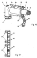
- Fig. 16 only a short end portion of the heat protection sleeve 80 is shown, but it may extend over the entire length or at least over a partial length of the fluid line 2.
- the heat-insulating envelope 80 is fixed to at least one end region on or in the housing 8 of the line connector 4.
- the heat protection cover 80 is outside with its end face in front of the housing 8, but it can also be guided into the housing 8.
- a retaining clip 82 is expediently provided according to FIGS.
- 16 and 17 consists of two preferably connected via a film hinge 84 halves, which can be folded and locked together so that then the retaining clip 82 surrounds the heat protection sleeve 80 annularly and positively and / or positively receives.
- the retaining clip 82 is connected or connectable to the housing 8 in particular via latching means 86, the heat shield 80 is fixed relative to the housing 8.
- the locking means 86 are formed analogous to the locking means 68 of the branch 64.
- the heat shield 80 may have a corresponding groove-like on its outer surface Profiling (not shown), in which the elements 88 can engage radially.
- the heat protection envelope 80 consists essentially of a metal foil, preferably an aluminum foil, wherein it may preferably have an internal reinforcement, in particular made of a laminated glass fabric.
- the metal foil may also consist of (possibly high-alloyed) stainless steel and of several layers, for. B. a first (inner) aluminum layer and a second (outer) stainless steel layer.
- special means for zugentlastenden fixation of / the Ranleiterls 26 are formed within the housing 8, in particular in the form of a deflection clamp 90 through which the or the connecting conductor 26 at least easily ( Fig. 19 ) or preferably several times ( Fig. 18 ) are deflected by clamping.
- the feed-through opening 62 for the connecting conductor or leads 26 can be equipped with an additional closing element, which is not recognizable in the drawings, which encloses the connecting conductors 26 in an elastically sealing manner.
- an additional closing element which is not recognizable in the drawings, which encloses the connecting conductors 26 in an elastically sealing manner.
- For a version without connecting conductor 26 may also be a not shown closure element, for. B. in the form of a blind plug into the passage opening 62 are used to close the housing 8 at this point tightly.
Landscapes
- Engineering & Computer Science (AREA)
- General Engineering & Computer Science (AREA)
- Mechanical Engineering (AREA)
- Pipe Accessories (AREA)
- Connector Housings Or Holding Contact Members (AREA)
- Instantaneous Water Boilers, Portable Hot-Water Supply Apparatuses, And Control Of Portable Hot-Water Supply Apparatuses (AREA)
- Resistance Heating (AREA)
- Control Or Security For Electrophotography (AREA)
- Discharging, Photosensitive Material Shape In Electrophotography (AREA)
Priority Applications (3)
| Application Number | Priority Date | Filing Date | Title |
|---|---|---|---|
| PL13185702T PL2679874T3 (pl) | 2009-06-23 | 2010-06-24 | Elektrycznie ogrzewalny przewód dla mediów oraz złączka przewodowa |
| PL10730133T PL2446180T5 (pl) | 2009-06-23 | 2010-06-24 | Elektrycznie ogrzewalny przewód dla mediów oraz złączka przewodowa |
| EP13185702.1A EP2679874B1 (de) | 2009-06-23 | 2010-06-24 | Elektrisch beheizbare Medienleitung mit Leitungsverbinder |
Applications Claiming Priority (4)
| Application Number | Priority Date | Filing Date | Title |
|---|---|---|---|
| DE202009008703 | 2009-06-23 | ||
| DE202009008763 | 2009-06-24 | ||
| DE202009012230U DE202009012230U1 (de) | 2009-06-23 | 2009-09-10 | Elektrisch beheizbare Medienleitung sowie Leitungsverbinder |
| PCT/EP2010/059033 WO2010149757A1 (de) | 2009-06-23 | 2010-06-24 | Elektrisch beheizbare medienleitung sowie leitungsverbinder |
Related Child Applications (3)
| Application Number | Title | Priority Date | Filing Date |
|---|---|---|---|
| EP13185702.1A Division EP2679874B1 (de) | 2009-06-23 | 2010-06-24 | Elektrisch beheizbare Medienleitung mit Leitungsverbinder |
| EP13185702.1A Division-Into EP2679874B1 (de) | 2009-06-23 | 2010-06-24 | Elektrisch beheizbare Medienleitung mit Leitungsverbinder |
| EP13185702.1 Division-Into | 2013-09-24 |
Publications (3)
| Publication Number | Publication Date |
|---|---|
| EP2446180A1 EP2446180A1 (de) | 2012-05-02 |
| EP2446180B1 EP2446180B1 (de) | 2013-11-06 |
| EP2446180B2 true EP2446180B2 (de) | 2017-04-26 |
Family
ID=43049602
Family Applications (2)
| Application Number | Title | Priority Date | Filing Date |
|---|---|---|---|
| EP10730133.5A Active EP2446180B2 (de) | 2009-06-23 | 2010-06-24 | Elektrisch beheizbare medienleitung sowie leitungsverbinder |
| EP13185702.1A Active EP2679874B1 (de) | 2009-06-23 | 2010-06-24 | Elektrisch beheizbare Medienleitung mit Leitungsverbinder |
Family Applications After (1)
| Application Number | Title | Priority Date | Filing Date |
|---|---|---|---|
| EP13185702.1A Active EP2679874B1 (de) | 2009-06-23 | 2010-06-24 | Elektrisch beheizbare Medienleitung mit Leitungsverbinder |
Country Status (7)
| Country | Link |
|---|---|
| US (1) | US8591241B2 (pl) |
| EP (2) | EP2446180B2 (pl) |
| DE (1) | DE202009012230U1 (pl) |
| ES (2) | ES2437915T5 (pl) |
| MX (1) | MX2011013066A (pl) |
| PL (2) | PL2446180T5 (pl) |
| WO (1) | WO2010149757A1 (pl) |
Families Citing this family (28)
| Publication number | Priority date | Publication date | Assignee | Title |
|---|---|---|---|---|
| EP2137449B2 (de) * | 2007-04-26 | 2018-10-17 | Voss Automotive GmbH | Leitungsverbinder für medienleitungen |
| US9651185B2 (en) | 2008-03-19 | 2017-05-16 | Voss Automotive Gmbh | Line connector for media lines |
| DE102010035028B4 (de) * | 2010-08-20 | 2013-07-18 | Voss Automotive Gmbh | Beheizbare Leitungsverbinder mit Isolations- und/oder Schutzabdeckung und beheizbare Medienleitung mit zumindest einem Leitungsverbinder mit Isolations- und/oder Schutzabdeckung |
| DE102010053737A1 (de) * | 2010-12-08 | 2012-06-14 | Voss Automotive Gmbh | Beheizbare Fluidleitung, deren Verwendung sowie Verfahren zu ihrer Herstellung |
| DE102011120356A1 (de) | 2011-12-07 | 2013-06-13 | Voss Automotive Gmbh | Konfektionierte Medienleitung und Verfahren zum Konfektionieren einer Medienleitung mit innenliegenden Heizelementen |
| JP6131277B2 (ja) | 2012-02-28 | 2017-05-17 | ノーマ・ユー・エス・ホールディング・リミテッド・ライアビリティ・カンパニーNorma U. S. Holding Llc | 自動車選択的接触還元(scr)システムのセンサ保持部およびアセンブリ |
| DE102012018069A1 (de) * | 2012-09-13 | 2014-03-13 | Eugen Forschner Gmbh | Vorrichtung zum Verbinden von Fluid führenden Leitungen |
| DE202013101265U1 (de) * | 2013-03-25 | 2014-06-26 | Rehau Ag + Co. | Medienleitung |
| EP2876273B1 (de) * | 2013-11-22 | 2017-01-04 | TI Automotive (Heidelberg) GmbH | Verbindungsaggregat aus einer beheizbaren Kraftfahrzeugleitung und einem beheizbaren Verbinder |
| JPWO2015098684A1 (ja) * | 2013-12-25 | 2017-03-23 | ニッタ株式会社 | 継手カバー |
| DE202014100268U1 (de) | 2014-01-23 | 2015-04-27 | Rehau Ag + Co | Medienleitung |
| US11174148B2 (en) * | 2014-04-18 | 2021-11-16 | Wayne Fueling Systems Llc | Devices and methods for heating fluid dispensers, hoses, and nozzles |
| US10597285B2 (en) | 2014-04-18 | 2020-03-24 | Wayne Fueling Systems Llc | Devices and methods for heating fuel hoses and nozzles |
| FR3022581B1 (fr) * | 2014-06-19 | 2016-07-01 | Peugeot Citroen Automobiles Sa | Systeme de reduction selective catalytique muni d'un dispositif d'isolation actif |
| DE202014105908U1 (de) * | 2014-12-06 | 2015-01-14 | Eugen Forschner Gmbh | Beheizungssystem für eine fluidführende Leitung |
| US20170023164A1 (en) * | 2015-07-24 | 2017-01-26 | Eichenauer Heizelemente Gmbh & Co. Kg | Pipe connector and method for manufacturing a pipe connector |
| DE102016109051A1 (de) | 2015-10-21 | 2017-04-27 | Voss Automotive Gmbh | Steckverbinder für Medienleitungen |
| EP3211190B1 (de) * | 2016-02-23 | 2019-04-17 | TI Automotive (Fuldabrück) GmbH | Verbinderanordnung mit zumindest einem verbinder und zumindest einer medienleitung |
| CN106090484B (zh) * | 2016-08-07 | 2018-06-26 | 广东星艺装饰集团股份有限公司 | 带有方便等电位线连接的金属内牙水管接头 |
| US10396500B2 (en) | 2016-08-31 | 2019-08-27 | Norma U.S. Holding Llc | Electrically conductive conduit assembly |
| DE202016107103U1 (de) * | 2016-12-19 | 2018-03-21 | Voss Automotive Gmbh | Leitungsstrang zur temperierten Führung eines Reduktionsmittels für die Abgasnachbehandlung einer Brennkraftmaschine |
| EP3382255B1 (de) * | 2017-03-29 | 2019-07-03 | TI Automotive (Fuldabrück) GmbH | Rohrleitung umfassend einen verbinder sowie verfahren zum betrieb dieser rohrleitung |
| EP3382254B1 (de) | 2017-03-29 | 2020-06-03 | TI Automotive (Fuldabrück) GmbH | Beheizte rohrleitung mit stecker sowie ein verfahren zum betrieb dieser rohrleitung |
| IT201700094931A1 (it) | 2017-08-22 | 2019-02-22 | Hutchinson Srl | Connettore per un condotto per un fluido riscaldabile, in particolare di un sistema scr o un sistema di iniezione ad acqua |
| DE102018103571A1 (de) * | 2018-02-16 | 2019-08-22 | Voss Automotive Gmbh | Verbindungsanordnung zum Verbinden von beheizbaren Fluidleitungen |
| DE102018107004B4 (de) * | 2018-03-23 | 2025-11-06 | Voss Automotive Gmbh | Beheizte Medienleitung mit Fixierteil |
| IT201900007016A1 (it) * | 2019-05-20 | 2020-11-20 | Hutchinson Srl | Sistema di collegamento idraulico ed elettrico per una pluralità di condotti configurati per essere attraversati da un fluido riscaldabile elettricamente. |
| FR3106390B1 (fr) * | 2020-01-20 | 2021-12-10 | Hutchinson | Coque chauffante pour raccord trois voies |
Citations (5)
| Publication number | Priority date | Publication date | Assignee | Title |
|---|---|---|---|---|
| DE3837851A1 (de) † | 1988-11-08 | 1990-05-10 | Heraeus Wittmann Gmbh | Elektrisch beheizbarer schlauch, insbesondere fuer scheiben- oder scheinwerfer-waschanlagen von kraftfahrzeugen |
| DE29715336U1 (de) † | 1997-08-27 | 1997-11-06 | Kromberg & Schubert, 42389 Wuppertal | Heizschlauchanschlußstück |
| EP1513227A1 (de) † | 2003-09-03 | 2005-03-09 | MAN Nutzfahrzeuge Aktiengesellschaft | Vorrichtung zur Führung eines fliessfähigen Mediums |
| WO2008131993A1 (de) † | 2007-04-26 | 2008-11-06 | Voss Automotive Gmbh | Leitungsverbinder für medienleitungen |
| WO2009013342A2 (de) † | 2007-07-26 | 2009-01-29 | Voss Automotive Gmbh | Konfektionierte medienleitung |
Family Cites Families (7)
| Publication number | Priority date | Publication date | Assignee | Title |
|---|---|---|---|---|
| NO311277B1 (no) * | 1999-12-28 | 2001-11-05 | Nexans | Kopling for varmekabel for offshore produksjonsrörledning |
| NO327252B1 (no) * | 2006-12-14 | 2009-05-25 | Nexans | Kabel til en rorledningsforbindelse |
| DE202007009588U1 (de) | 2007-04-26 | 2008-09-04 | Voss Automotive Gmbh | Leitungsverbinder für Medienleitungen |
| EP2167860B1 (de) * | 2007-06-12 | 2012-11-14 | ContiTech Schlauch GmbH | Anschlussvorrichtung für medienführende, elektrisch beheizbare schläuche |
| DE202008004954U1 (de) | 2008-04-09 | 2009-08-13 | Voss Automotive Gmbh | Leitungsverbinder für Medienleitungen sowie konfektionierte Medienleitung mit mindestens einem solchen Leitungsverbinder |
| DE202007018089U1 (de) | 2007-12-21 | 2009-05-07 | Voss Automotive Gmbh | Beheizbare Medienleitung |
| DE202007018086U1 (de) | 2007-12-21 | 2009-05-07 | Voss Automotive Gmbh | Leitungsverbinder für Medienleitungen sowie konfektionierte Medienleitung mit mindestens einem solchen Leitungsverbinder |
-
2009
- 2009-09-10 DE DE202009012230U patent/DE202009012230U1/de not_active Expired - Lifetime
-
2010
- 2010-06-24 US US13/380,290 patent/US8591241B2/en active Active
- 2010-06-24 MX MX2011013066A patent/MX2011013066A/es active IP Right Grant
- 2010-06-24 EP EP10730133.5A patent/EP2446180B2/de active Active
- 2010-06-24 PL PL10730133T patent/PL2446180T5/pl unknown
- 2010-06-24 PL PL13185702T patent/PL2679874T3/pl unknown
- 2010-06-24 ES ES10730133.5T patent/ES2437915T5/es active Active
- 2010-06-24 ES ES13185702.1T patent/ES2551909T3/es active Active
- 2010-06-24 WO PCT/EP2010/059033 patent/WO2010149757A1/de not_active Ceased
- 2010-06-24 EP EP13185702.1A patent/EP2679874B1/de active Active
Patent Citations (5)
| Publication number | Priority date | Publication date | Assignee | Title |
|---|---|---|---|---|
| DE3837851A1 (de) † | 1988-11-08 | 1990-05-10 | Heraeus Wittmann Gmbh | Elektrisch beheizbarer schlauch, insbesondere fuer scheiben- oder scheinwerfer-waschanlagen von kraftfahrzeugen |
| DE29715336U1 (de) † | 1997-08-27 | 1997-11-06 | Kromberg & Schubert, 42389 Wuppertal | Heizschlauchanschlußstück |
| EP1513227A1 (de) † | 2003-09-03 | 2005-03-09 | MAN Nutzfahrzeuge Aktiengesellschaft | Vorrichtung zur Führung eines fliessfähigen Mediums |
| WO2008131993A1 (de) † | 2007-04-26 | 2008-11-06 | Voss Automotive Gmbh | Leitungsverbinder für medienleitungen |
| WO2009013342A2 (de) † | 2007-07-26 | 2009-01-29 | Voss Automotive Gmbh | Konfektionierte medienleitung |
Also Published As
| Publication number | Publication date |
|---|---|
| DE202009012230U1 (de) | 2010-11-04 |
| PL2679874T3 (pl) | 2016-02-29 |
| US20120100735A1 (en) | 2012-04-26 |
| EP2679874B1 (de) | 2015-09-09 |
| PL2446180T5 (pl) | 2017-10-31 |
| ES2437915T3 (es) | 2014-01-15 |
| EP2446180A1 (de) | 2012-05-02 |
| US8591241B2 (en) | 2013-11-26 |
| EP2679874A1 (de) | 2014-01-01 |
| MX2011013066A (es) | 2013-01-21 |
| ES2551909T3 (es) | 2015-11-24 |
| EP2446180B1 (de) | 2013-11-06 |
| WO2010149757A8 (de) | 2012-05-31 |
| WO2010149757A1 (de) | 2010-12-29 |
| PL2446180T3 (pl) | 2014-04-30 |
| ES2437915T5 (es) | 2017-08-09 |
Similar Documents
| Publication | Publication Date | Title |
|---|---|---|
| EP2446180B2 (de) | Elektrisch beheizbare medienleitung sowie leitungsverbinder | |
| EP2222995B1 (de) | Leitungsverbinder für medienleitungen sowie konfektionierte medienleitung mit mindestens einem solchen leitungsverbinder | |
| EP2347163B2 (de) | Leitungsverbinder für medienleitungen | |
| EP2220419B1 (de) | Beheizbare medienleitung | |
| EP2055535B2 (de) | Kabelsatz, insbesondere ein Hochvoltkabelsatz für ein Kraftfahrzeug, sowie eine Vorrichtung zur Durchführung eines elektrischen Kabels und zur Anbindung einer Abschirmung des Kabels | |
| DE102010032189B4 (de) | Verfahren zum Herstellen einer beheizbaren Medienleitung und beheizbare Medienleitung, hergestellt nach dem Verfahren | |
| EP3342006B1 (de) | Elektrische kabelbaugruppe | |
| EP2766651B1 (de) | Konfektionierte medienleitung mit zumindest einer beheizbaren medienleitung und mit zumindest einem zumindest teilweise beheizbaren leitungsverbinder | |
| EP3076487B1 (de) | Kunststoff-dichtungshülle für eine leiterverbindung,verbindungsteil, abdeckmutter sowie abgedichtete verbindung zwischen zwei leitern | |
| EP2596275B9 (de) | Beheizbare medienleitung | |
| DE202011106751U1 (de) | Zumindest teilweise beheizbarer Leitungsverbinder für eine beheizbare Medienleitung sowie konfektionierte Medienleitung mit einem solchen Leitungsverbinder | |
| DE10058265C1 (de) | Kabelstecker für elektrische Kabelverbindungen | |
| EP2896093B1 (de) | Elektrischer kontaktstecker sowie steckergehäuse | |
| EP1796216B1 (de) | Kabelschuh | |
| EP2245705B1 (de) | Steckverbinderelement mit abdichtung im kabelanschlussbereich | |
| EP2420715B1 (de) | Isolations- und/oder Schutzabdeckung für beheizbare Leitungsverbinder | |
| DE202007018086U1 (de) | Leitungsverbinder für Medienleitungen sowie konfektionierte Medienleitung mit mindestens einem solchen Leitungsverbinder | |
| DE202008004954U1 (de) | Leitungsverbinder für Medienleitungen sowie konfektionierte Medienleitung mit mindestens einem solchen Leitungsverbinder | |
| DE4206014C2 (de) | Anschlußelement zur Haltung eines Schutzschlauches | |
| EP3737885B1 (de) | Konfektionierte fluidleitung | |
| WO2018059666A1 (de) | Verbindungsteil, abdeckmutter, kunststoff-dichtungshülle für eine leiterverbindung und abgedichtete verbindung zwischen zwei leitern | |
| DE102011115890A1 (de) | Zumindest teilweise beheizbarer Leitungsverbinder für einebeheizbare Medienleitung sowie konfektionierte Medienleitung mit einem solchen Leitungsverbinder |
Legal Events
| Date | Code | Title | Description |
|---|---|---|---|
| PUAI | Public reference made under article 153(3) epc to a published international application that has entered the european phase |
Free format text: ORIGINAL CODE: 0009012 |
|
| 17P | Request for examination filed |
Effective date: 20111122 |
|
| AK | Designated contracting states |
Kind code of ref document: A1 Designated state(s): AL AT BE BG CH CY CZ DE DK EE ES FI FR GB GR HR HU IE IS IT LI LT LU LV MC MK MT NL NO PL PT RO SE SI SK SM TR |
|
| DAX | Request for extension of the european patent (deleted) | ||
| 17Q | First examination report despatched |
Effective date: 20121018 |
|
| REG | Reference to a national code |
Ref country code: DE Ref legal event code: R079 Ref document number: 502010005296 Country of ref document: DE Free format text: PREVIOUS MAIN CLASS: F16L0025010000 Ipc: H01R0013000000 |
|
| GRAP | Despatch of communication of intention to grant a patent |
Free format text: ORIGINAL CODE: EPIDOSNIGR1 |
|
| RIC1 | Information provided on ipc code assigned before grant |
Ipc: F16L 53/00 20060101ALI20130430BHEP Ipc: H01R 13/00 20060101AFI20130430BHEP Ipc: H05B 3/40 20060101ALI20130430BHEP Ipc: F16L 25/01 20060101ALI20130430BHEP |
|
| INTG | Intention to grant announced |
Effective date: 20130604 |
|
| GRAS | Grant fee paid |
Free format text: ORIGINAL CODE: EPIDOSNIGR3 |
|
| GRAA | (expected) grant |
Free format text: ORIGINAL CODE: 0009210 |
|
| AK | Designated contracting states |
Kind code of ref document: B1 Designated state(s): AL AT BE BG CH CY CZ DE DK EE ES FI FR GB GR HR HU IE IS IT LI LT LU LV MC MK MT NL NO PL PT RO SE SI SK SM TR |
|
| REG | Reference to a national code |
Ref country code: GB Ref legal event code: FG4D Free format text: NOT ENGLISH |
|
| REG | Reference to a national code |
Ref country code: CH Ref legal event code: EP |
|
| REG | Reference to a national code |
Ref country code: AT Ref legal event code: REF Ref document number: 639985 Country of ref document: AT Kind code of ref document: T Effective date: 20131215 |
|
| REG | Reference to a national code |
Ref country code: IE Ref legal event code: FG4D Free format text: LANGUAGE OF EP DOCUMENT: GERMAN |
|
| REG | Reference to a national code |
Ref country code: NL Ref legal event code: T3 |
|
| REG | Reference to a national code |
Ref country code: DE Ref legal event code: R096 Ref document number: 502010005296 Country of ref document: DE Effective date: 20140102 |
|
| REG | Reference to a national code |
Ref country code: ES Ref legal event code: FG2A Ref document number: 2437915 Country of ref document: ES Kind code of ref document: T3 Effective date: 20140115 |
|
| REG | Reference to a national code |
Ref country code: SE Ref legal event code: TRGR |
|
| REG | Reference to a national code |
Ref country code: LT Ref legal event code: MG4D |
|
| PG25 | Lapsed in a contracting state [announced via postgrant information from national office to epo] |
Ref country code: NO Free format text: LAPSE BECAUSE OF FAILURE TO SUBMIT A TRANSLATION OF THE DESCRIPTION OR TO PAY THE FEE WITHIN THE PRESCRIBED TIME-LIMIT Effective date: 20140206 Ref country code: FI Free format text: LAPSE BECAUSE OF FAILURE TO SUBMIT A TRANSLATION OF THE DESCRIPTION OR TO PAY THE FEE WITHIN THE PRESCRIBED TIME-LIMIT Effective date: 20131106 Ref country code: LT Free format text: LAPSE BECAUSE OF FAILURE TO SUBMIT A TRANSLATION OF THE DESCRIPTION OR TO PAY THE FEE WITHIN THE PRESCRIBED TIME-LIMIT Effective date: 20131106 Ref country code: HR Free format text: LAPSE BECAUSE OF FAILURE TO SUBMIT A TRANSLATION OF THE DESCRIPTION OR TO PAY THE FEE WITHIN THE PRESCRIBED TIME-LIMIT Effective date: 20131106 Ref country code: IS Free format text: LAPSE BECAUSE OF FAILURE TO SUBMIT A TRANSLATION OF THE DESCRIPTION OR TO PAY THE FEE WITHIN THE PRESCRIBED TIME-LIMIT Effective date: 20140306 |
|
| REG | Reference to a national code |
Ref country code: PL Ref legal event code: T3 |
|
| PG25 | Lapsed in a contracting state [announced via postgrant information from national office to epo] |
Ref country code: LV Free format text: LAPSE BECAUSE OF FAILURE TO SUBMIT A TRANSLATION OF THE DESCRIPTION OR TO PAY THE FEE WITHIN THE PRESCRIBED TIME-LIMIT Effective date: 20131106 |
|
| PG25 | Lapsed in a contracting state [announced via postgrant information from national office to epo] |
Ref country code: PT Free format text: LAPSE BECAUSE OF FAILURE TO SUBMIT A TRANSLATION OF THE DESCRIPTION OR TO PAY THE FEE WITHIN THE PRESCRIBED TIME-LIMIT Effective date: 20140306 |
|
| REG | Reference to a national code |
Ref country code: DE Ref legal event code: R026 Ref document number: 502010005296 Country of ref document: DE |
|
| PG25 | Lapsed in a contracting state [announced via postgrant information from national office to epo] |
Ref country code: EE Free format text: LAPSE BECAUSE OF FAILURE TO SUBMIT A TRANSLATION OF THE DESCRIPTION OR TO PAY THE FEE WITHIN THE PRESCRIBED TIME-LIMIT Effective date: 20131106 |
|
| PLBI | Opposition filed |
Free format text: ORIGINAL CODE: 0009260 |
|
| PG25 | Lapsed in a contracting state [announced via postgrant information from national office to epo] |
Ref country code: CZ Free format text: LAPSE BECAUSE OF FAILURE TO SUBMIT A TRANSLATION OF THE DESCRIPTION OR TO PAY THE FEE WITHIN THE PRESCRIBED TIME-LIMIT Effective date: 20131106 Ref country code: RO Free format text: LAPSE BECAUSE OF FAILURE TO SUBMIT A TRANSLATION OF THE DESCRIPTION OR TO PAY THE FEE WITHIN THE PRESCRIBED TIME-LIMIT Effective date: 20131106 Ref country code: SK Free format text: LAPSE BECAUSE OF FAILURE TO SUBMIT A TRANSLATION OF THE DESCRIPTION OR TO PAY THE FEE WITHIN THE PRESCRIBED TIME-LIMIT Effective date: 20131106 |
|
| 26 | Opposition filed |
Opponent name: TI AUTOMOTIVE (HEIDELBERG) GMBH Effective date: 20140729 |
|
| PLAX | Notice of opposition and request to file observation + time limit sent |
Free format text: ORIGINAL CODE: EPIDOSNOBS2 |
|
| PG25 | Lapsed in a contracting state [announced via postgrant information from national office to epo] |
Ref country code: DK Free format text: LAPSE BECAUSE OF FAILURE TO SUBMIT A TRANSLATION OF THE DESCRIPTION OR TO PAY THE FEE WITHIN THE PRESCRIBED TIME-LIMIT Effective date: 20131106 |
|
| REG | Reference to a national code |
Ref country code: DE Ref legal event code: R026 Ref document number: 502010005296 Country of ref document: DE Effective date: 20140729 |
|
| PLAF | Information modified related to communication of a notice of opposition and request to file observations + time limit |
Free format text: ORIGINAL CODE: EPIDOSCOBS2 |
|
| PG25 | Lapsed in a contracting state [announced via postgrant information from national office to epo] |
Ref country code: LU Free format text: LAPSE BECAUSE OF FAILURE TO SUBMIT A TRANSLATION OF THE DESCRIPTION OR TO PAY THE FEE WITHIN THE PRESCRIBED TIME-LIMIT Effective date: 20140624 Ref country code: MC Free format text: LAPSE BECAUSE OF FAILURE TO SUBMIT A TRANSLATION OF THE DESCRIPTION OR TO PAY THE FEE WITHIN THE PRESCRIBED TIME-LIMIT Effective date: 20131106 |
|
| REG | Reference to a national code |
Ref country code: CH Ref legal event code: PL |
|
| GBPC | Gb: european patent ceased through non-payment of renewal fee |
Effective date: 20140624 |
|
| PG25 | Lapsed in a contracting state [announced via postgrant information from national office to epo] |
Ref country code: SI Free format text: LAPSE BECAUSE OF FAILURE TO SUBMIT A TRANSLATION OF THE DESCRIPTION OR TO PAY THE FEE WITHIN THE PRESCRIBED TIME-LIMIT Effective date: 20131106 |
|
| REG | Reference to a national code |
Ref country code: IE Ref legal event code: MM4A |
|
| PLBB | Reply of patent proprietor to notice(s) of opposition received |
Free format text: ORIGINAL CODE: EPIDOSNOBS3 |
|
| PG25 | Lapsed in a contracting state [announced via postgrant information from national office to epo] |
Ref country code: CH Free format text: LAPSE BECAUSE OF NON-PAYMENT OF DUE FEES Effective date: 20140630 Ref country code: LI Free format text: LAPSE BECAUSE OF NON-PAYMENT OF DUE FEES Effective date: 20140630 Ref country code: IE Free format text: LAPSE BECAUSE OF NON-PAYMENT OF DUE FEES Effective date: 20140624 |
|
| PG25 | Lapsed in a contracting state [announced via postgrant information from national office to epo] |
Ref country code: GB Free format text: LAPSE BECAUSE OF NON-PAYMENT OF DUE FEES Effective date: 20140624 |
|
| PG25 | Lapsed in a contracting state [announced via postgrant information from national office to epo] |
Ref country code: MT Free format text: LAPSE BECAUSE OF FAILURE TO SUBMIT A TRANSLATION OF THE DESCRIPTION OR TO PAY THE FEE WITHIN THE PRESCRIBED TIME-LIMIT Effective date: 20131106 |
|
| PG25 | Lapsed in a contracting state [announced via postgrant information from national office to epo] |
Ref country code: SM Free format text: LAPSE BECAUSE OF FAILURE TO SUBMIT A TRANSLATION OF THE DESCRIPTION OR TO PAY THE FEE WITHIN THE PRESCRIBED TIME-LIMIT Effective date: 20131106 |
|
| REG | Reference to a national code |
Ref country code: FR Ref legal event code: PLFP Year of fee payment: 7 |
|
| PG25 | Lapsed in a contracting state [announced via postgrant information from national office to epo] |
Ref country code: BG Free format text: LAPSE BECAUSE OF FAILURE TO SUBMIT A TRANSLATION OF THE DESCRIPTION OR TO PAY THE FEE WITHIN THE PRESCRIBED TIME-LIMIT Effective date: 20131106 Ref country code: CY Free format text: LAPSE BECAUSE OF FAILURE TO SUBMIT A TRANSLATION OF THE DESCRIPTION OR TO PAY THE FEE WITHIN THE PRESCRIBED TIME-LIMIT Effective date: 20131106 Ref country code: GR Free format text: LAPSE BECAUSE OF FAILURE TO SUBMIT A TRANSLATION OF THE DESCRIPTION OR TO PAY THE FEE WITHIN THE PRESCRIBED TIME-LIMIT Effective date: 20140207 |
|
| PG25 | Lapsed in a contracting state [announced via postgrant information from national office to epo] |
Ref country code: HU Free format text: LAPSE BECAUSE OF FAILURE TO SUBMIT A TRANSLATION OF THE DESCRIPTION OR TO PAY THE FEE WITHIN THE PRESCRIBED TIME-LIMIT; INVALID AB INITIO Effective date: 20100624 Ref country code: TR Free format text: LAPSE BECAUSE OF FAILURE TO SUBMIT A TRANSLATION OF THE DESCRIPTION OR TO PAY THE FEE WITHIN THE PRESCRIBED TIME-LIMIT Effective date: 20131106 Ref country code: BE Free format text: LAPSE BECAUSE OF FAILURE TO SUBMIT A TRANSLATION OF THE DESCRIPTION OR TO PAY THE FEE WITHIN THE PRESCRIBED TIME-LIMIT Effective date: 20140630 |
|
| APBM | Appeal reference recorded |
Free format text: ORIGINAL CODE: EPIDOSNREFNO |
|
| APBP | Date of receipt of notice of appeal recorded |
Free format text: ORIGINAL CODE: EPIDOSNNOA2O |
|
| REG | Reference to a national code |
Ref country code: AT Ref legal event code: MM01 Ref document number: 639985 Country of ref document: AT Kind code of ref document: T Effective date: 20150624 |
|
| APAH | Appeal reference modified |
Free format text: ORIGINAL CODE: EPIDOSCREFNO |
|
| APBU | Appeal procedure closed |
Free format text: ORIGINAL CODE: EPIDOSNNOA9O |
|
| PG25 | Lapsed in a contracting state [announced via postgrant information from national office to epo] |
Ref country code: AT Free format text: LAPSE BECAUSE OF NON-PAYMENT OF DUE FEES Effective date: 20150624 |
|
| PUAH | Patent maintained in amended form |
Free format text: ORIGINAL CODE: 0009272 |
|
| STAA | Information on the status of an ep patent application or granted ep patent |
Free format text: STATUS: PATENT MAINTAINED AS AMENDED |
|
| 27A | Patent maintained in amended form |
Effective date: 20170426 |
|
| AK | Designated contracting states |
Kind code of ref document: B2 Designated state(s): AL AT BE BG CH CY CZ DE DK EE ES FI FR GB GR HR HU IE IS IT LI LT LU LV MC MK MT NL NO PL PT RO SE SI SK SM TR |
|
| REG | Reference to a national code |
Ref country code: DE Ref legal event code: R102 Ref document number: 502010005296 Country of ref document: DE |
|
| REG | Reference to a national code |
Ref country code: SE Ref legal event code: RPEO |
|
| REG | Reference to a national code |
Ref country code: FR Ref legal event code: PLFP Year of fee payment: 8 |
|
| REG | Reference to a national code |
Ref country code: ES Ref legal event code: DC2A Ref document number: 2437915 Country of ref document: ES Kind code of ref document: T5 Effective date: 20170809 Ref country code: NL Ref legal event code: FP |
|
| PGFP | Annual fee paid to national office [announced via postgrant information from national office to epo] |
Ref country code: ES Payment date: 20170801 Year of fee payment: 8 |
|
| REG | Reference to a national code |
Ref country code: FR Ref legal event code: PLFP Year of fee payment: 9 |
|
| PG25 | Lapsed in a contracting state [announced via postgrant information from national office to epo] |
Ref country code: MK Free format text: LAPSE BECAUSE OF FAILURE TO SUBMIT A TRANSLATION OF THE DESCRIPTION OR TO PAY THE FEE WITHIN THE PRESCRIBED TIME-LIMIT Effective date: 20131106 |
|
| PG25 | Lapsed in a contracting state [announced via postgrant information from national office to epo] |
Ref country code: AL Free format text: LAPSE BECAUSE OF FAILURE TO SUBMIT A TRANSLATION OF THE DESCRIPTION OR TO PAY THE FEE WITHIN THE PRESCRIBED TIME-LIMIT Effective date: 20131106 |
|
| REG | Reference to a national code |
Ref country code: ES Ref legal event code: FD2A Effective date: 20190916 |
|
| PG25 | Lapsed in a contracting state [announced via postgrant information from national office to epo] |
Ref country code: ES Free format text: LAPSE BECAUSE OF NON-PAYMENT OF DUE FEES Effective date: 20180625 |
|
| P01 | Opt-out of the competence of the unified patent court (upc) registered |
Effective date: 20230526 |
|
| PGFP | Annual fee paid to national office [announced via postgrant information from national office to epo] |
Ref country code: NL Payment date: 20250515 Year of fee payment: 16 |
|
| PGFP | Annual fee paid to national office [announced via postgrant information from national office to epo] |
Ref country code: PL Payment date: 20250410 Year of fee payment: 16 |
|
| PGFP | Annual fee paid to national office [announced via postgrant information from national office to epo] |
Ref country code: IT Payment date: 20250409 Year of fee payment: 16 |
|
| PGFP | Annual fee paid to national office [announced via postgrant information from national office to epo] |
Ref country code: FR Payment date: 20250509 Year of fee payment: 16 |
|
| PGFP | Annual fee paid to national office [announced via postgrant information from national office to epo] |
Ref country code: SE Payment date: 20250513 Year of fee payment: 16 |
|
| PGFP | Annual fee paid to national office [announced via postgrant information from national office to epo] |
Ref country code: DE Payment date: 20250821 Year of fee payment: 16 |