EP2446977A1 - Verfahren zur Herstellung eines Rohrprofils - Google Patents
Verfahren zur Herstellung eines Rohrprofils Download PDFInfo
- Publication number
- EP2446977A1 EP2446977A1 EP11005966A EP11005966A EP2446977A1 EP 2446977 A1 EP2446977 A1 EP 2446977A1 EP 11005966 A EP11005966 A EP 11005966A EP 11005966 A EP11005966 A EP 11005966A EP 2446977 A1 EP2446977 A1 EP 2446977A1
- Authority
- EP
- European Patent Office
- Prior art keywords
- mpa
- profile
- section
- shaped
- circular
- Prior art date
- Legal status (The legal status is an assumption and is not a legal conclusion. Google has not performed a legal analysis and makes no representation as to the accuracy of the status listed.)
- Granted
Links
Images

Classifications
-
- B—PERFORMING OPERATIONS; TRANSPORTING
- B21—MECHANICAL METAL-WORKING WITHOUT ESSENTIALLY REMOVING MATERIAL; PUNCHING METAL
- B21D—WORKING OR PROCESSING OF SHEET METAL OR METAL TUBES, RODS OR PROFILES WITHOUT ESSENTIALLY REMOVING MATERIAL; PUNCHING METAL
- B21D53/00—Making other particular articles
- B21D53/88—Making other particular articles other parts for vehicles, e.g. cowlings, mudguards
-
- B—PERFORMING OPERATIONS; TRANSPORTING
- B21—MECHANICAL METAL-WORKING WITHOUT ESSENTIALLY REMOVING MATERIAL; PUNCHING METAL
- B21D—WORKING OR PROCESSING OF SHEET METAL OR METAL TUBES, RODS OR PROFILES WITHOUT ESSENTIALLY REMOVING MATERIAL; PUNCHING METAL
- B21D22/00—Shaping without cutting, by stamping, spinning, or deep-drawing
- B21D22/02—Stamping using rigid devices or tools
- B21D22/025—Stamping using rigid devices or tools for tubular articles
-
- C—CHEMISTRY; METALLURGY
- C21—METALLURGY OF IRON
- C21D—MODIFYING THE PHYSICAL STRUCTURE OF FERROUS METALS; GENERAL DEVICES FOR HEAT TREATMENT OF FERROUS OR NON-FERROUS METALS OR ALLOYS; MAKING METAL MALLEABLE, e.g. BY DECARBURISATION OR TEMPERING
- C21D1/00—General methods or devices for heat treatment, e.g. annealing, hardening, quenching or tempering
- C21D1/62—Quenching devices
- C21D1/673—Quenching devices for die quenching
-
- C—CHEMISTRY; METALLURGY
- C21—METALLURGY OF IRON
- C21D—MODIFYING THE PHYSICAL STRUCTURE OF FERROUS METALS; GENERAL DEVICES FOR HEAT TREATMENT OF FERROUS OR NON-FERROUS METALS OR ALLOYS; MAKING METAL MALLEABLE, e.g. BY DECARBURISATION OR TEMPERING
- C21D7/00—Modifying the physical properties of iron or steel by deformation
- C21D7/13—Modifying the physical properties of iron or steel by deformation by hot working
-
- C—CHEMISTRY; METALLURGY
- C21—METALLURGY OF IRON
- C21D—MODIFYING THE PHYSICAL STRUCTURE OF FERROUS METALS; GENERAL DEVICES FOR HEAT TREATMENT OF FERROUS OR NON-FERROUS METALS OR ALLOYS; MAKING METAL MALLEABLE, e.g. BY DECARBURISATION OR TEMPERING
- C21D9/00—Heat treatment, e.g. annealing, hardening, quenching or tempering, adapted for particular articles; Furnaces therefor
- C21D9/0068—Heat treatment, e.g. annealing, hardening, quenching or tempering, adapted for particular articles; Furnaces therefor for particular articles not mentioned below
-
- C—CHEMISTRY; METALLURGY
- C21—METALLURGY OF IRON
- C21D—MODIFYING THE PHYSICAL STRUCTURE OF FERROUS METALS; GENERAL DEVICES FOR HEAT TREATMENT OF FERROUS OR NON-FERROUS METALS OR ALLOYS; MAKING METAL MALLEABLE, e.g. BY DECARBURISATION OR TEMPERING
- C21D9/00—Heat treatment, e.g. annealing, hardening, quenching or tempering, adapted for particular articles; Furnaces therefor
- C21D9/08—Heat treatment, e.g. annealing, hardening, quenching or tempering, adapted for particular articles; Furnaces therefor for tubular bodies or pipes
-
- C—CHEMISTRY; METALLURGY
- C21—METALLURGY OF IRON
- C21D—MODIFYING THE PHYSICAL STRUCTURE OF FERROUS METALS; GENERAL DEVICES FOR HEAT TREATMENT OF FERROUS OR NON-FERROUS METALS OR ALLOYS; MAKING METAL MALLEABLE, e.g. BY DECARBURISATION OR TEMPERING
- C21D2221/00—Treating localised areas of an article
- C21D2221/01—End parts (e.g. leading, trailing end)
-
- C—CHEMISTRY; METALLURGY
- C21—METALLURGY OF IRON
- C21D—MODIFYING THE PHYSICAL STRUCTURE OF FERROUS METALS; GENERAL DEVICES FOR HEAT TREATMENT OF FERROUS OR NON-FERROUS METALS OR ALLOYS; MAKING METAL MALLEABLE, e.g. BY DECARBURISATION OR TEMPERING
- C21D2221/00—Treating localised areas of an article
- C21D2221/02—Edge parts
Definitions
- the invention relates to a method for producing a tubular profile as a cross member for the torsion beam axle of a motor vehicle.
- Twist-beam axes are known in the art. It will do this, for example, on the EP 0 752 332 A1 directed.
- Such a known tubular profile has circular tubular sections at both ends.
- a double-walled U-shaped channel section is formed by forming.
- the transition areas between the circular ends and the U-shaped central part go continuously from circular to the U-shaped cross section over. It can additionally be provided in the end regions between the transition areas and the U-shaped longitudinal area an inward or outward indentation.
- a method for producing such a pipe profile is in EP 1 577 404 B 1 described.
- a tube of case steel is first cold formed and then subjected to a heat treatment, wherein after the heat treatment, a quenching and surface hardening takes place.
- the present invention seeks to provide an alternative method for producing such pipe profiles, which also can be carried out particularly cost and is easy to handle.
- the invention proposes a method for producing a tubular profile as a cross member for a torsion beam axle of a motor vehicle, in which a tube is austenitized from an air-hardening steel in a first process step, in a second process step while maintaining the ends with a circular cross-section of the middle Range is formed in one stage or two stages by means of a horrober- and -unterteils to a U-shaped cross-section warm, the transition areas between the circular ends and the central region continuously from circular to U-shaped cross section passing without tool contact or only with underside, one-sided tool contact be transformed.
- the ears formed during the deformation of the central region at the edges of the U-shaped cross section be held during the forming free of contact of the tool top and bottom. It is also preferable under certain circumstances for press-hardening to be carried out by hot-forming or simultaneously with the forging in the central region by cooling the upper and lower parts of the tool.
- the formed tubular profile is cooled to room temperature in air after the forming step.
- the deformed tube profile is cooled after the forming step with water mist.
- the tube profile to be produced by means of hot forming, optionally press hardening and subsequent cooling and simultaneous self-annealing in air and / or with water mist has in each case a circular cross section at its ends.
- the hot forming in the tool in a one- or two-stage process by means of a tool upper part and lower tool part a U-shaped cross section is generated in the central region.
- the lower tool part supports the pipe section only in the central region to be formed, while the upper tool part is also provided only in the central region and acts on the pipe section.
- the tool lower part trough-shaped according to Target contour of the finished pipe section may be formed in the central region, while the upper tool part is a trough-shaped punch, which has the contour of the central region of the pipe section to be generated.
- the transitions between the circular cross-section at the ends and the U-shaped cross-section in the central region are continuous over from one to the other cross section. Due to the hot forming and direct contact of the upper and lower tool parts in the central U-shaped cross section and the resulting higher cooling rates and the resulting lower temperatures on the pipe profile, higher strengths of at least 800 MPa, preferably 1000 MPa are achieved in this area than in the ears at the edges of the U-shaped cross section. This also applies to the circular cross sections at the ends. Here, too, a strength of at least 800 MPa, preferably 1000 MPa, is achieved, since a mandrel is introduced into the pipe at the pipe ends to support the shaping and supports the pipe ends from the inside. Again, the effect described is achieved by the direct contact of the mandrels with the pipe ends.
- air-hardening steel qualities are preferably available worldwide steel grades such as LH800 / 900 and MW 1000L is used. Details of these steels can be found, for example, in the material sheet "air-hardenable tempering steel", in hot-rolled and cold-rolled version, issue November 2006 (first edition) of Salzgitter Flachstahl AG or in material sheet 049 R, January 2009 edition, Salzgitter Mannesmann Rezision.
- the cooling of the formed tube profile can be done in the simplest form in air to room temperature.
- the cooling can also take place in the forming tool and then continue in air or the cooling can be accelerated by a water mist.
- the special effect in the forming is that in the areas in which a direct contact with tool parts or the like takes place, a higher strength is achieved while in In areas where there is no direct contact with tools or tool parts, a higher ductility during subsequent tempering is achieved.
- the material of the pipe profile is coated to prevent corrosion before Austenitmaschine.
- the austenitizing tube profile is galvanized or provided with an aluminum-silicon coating or generally with an anticorrosive coating,
- the deformation of the pipe profile can be done directly without inert gas.
- austenitization and hot forming are carried out under a protective gas atmosphere.
- a tube profile made of suitable air-hardening steel can be used, which is not corrosion-coated.
- the protective gas atmosphere prevents the ingress of oxygen and thus avoids undesired oxidation or scaling of the material.
- the tube profile is heated to 930 o C and over several minutes on this Temperature is maintained before the hot forming is performed immediately thereafter.
- the heating of the tube profile to Austenitmaschinestemperatur can be done for example in an oven or continuous furnace, or conductive or inductive.
- the heat treatment for the purpose of austenitizing at 930 ° C under nitrogen atmosphere, wherein the heat treatment is carried out for at least thirteen minutes, so that the desired component temperature is achieved.
- About a sealed removal and feeding the heated workpiece is fed to the two-stage hot forming, which reaches a defined material temperature before each forming process and in which there is a partial cooling of the component in the tool. Due to the protective gas atmosphere, the formation of scale is avoided.
- the final cooling preferably at open air, to room temperature, a higher ductility in the radii and transitions is achieved by lower cooling rates.
- the deformed tube profile is blasted after cooling.
- the deformed tube profile with glass beads, dry ice or balls, in particular steel balls or grains is blasted.
- the invention further relates to a tubular profile as a cross member for a torsion beam axle of a motor vehicle, consisting of a tubular profile with circular cross-section at the two ends, a middle double-walled U-shaped portion and transition portions which merge continuously from the circular ends in the U-shaped region.
- the invention proposes that the pipe profile consists of air-hardening steel having at the two ends a ring zone (a) with a strength of more than 800 MPa, preferably more than 1000 MPa , in the transition region (b) between the ends (a) and the U-shaped region (c) has a strength of at least 500 MPa to at most 800 MPa, in the U-shaped region (c) has a strength of at least 800 MPa, preferably at least 1000 MPa, and in the area of the ear-shaped edges of U-shaped area (c) a strength of 550 to 750 MPa.
- the invention further provides a pipe profile according to claim 11, produced by the method according to one of claims 1 to 10.
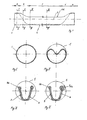
- the drawing figures show a finished tube profile, which is produced by the method according to the invention.
- the area over which these circular sections extend is indicated by a.
- This area a is followed by another area b.
- This area b is a transitional section continuously from the Section a in the U-shaped central area c passes.
- the invention is not limited to the embodiment, but in the context of the overall disclosure often variable.
Landscapes
- Chemical & Material Sciences (AREA)
- Engineering & Computer Science (AREA)
- Mechanical Engineering (AREA)
- Crystallography & Structural Chemistry (AREA)
- Materials Engineering (AREA)
- Metallurgy (AREA)
- Organic Chemistry (AREA)
- Physics & Mathematics (AREA)
- Thermal Sciences (AREA)
- Heat Treatment Of Articles (AREA)
Abstract
Description
- Die Erfindung betrifft ein Verfahren zur Herstellung eines Rohrprofils als Querträger für die Verbundlenkerachse eines Kraftfahrzeuges.
- Verbundlenkerachsen sind im Stand der Technik bekannt. Es wird dazu beispielsweise auf die
EP 0 752 332 A 1 verwiesen. Ein solches bekanntes Rohrprofil weist an beiden Enden kreisrunde rohrförmige Abschnitte auf. Im mittleren Längenbereich ist durch Umformung ein doppelwandiger U-förmiger Rinnenabschnitt gebildet. Die Übergangsbereiche zwischen den kreisrunden Enden und dem U-förmigen Mittelteil gehen kontinuierlich von kreisrunden zum U-förmigen Querschnitt über. Dabei kann zusätzlich noch in den Endbereichen zwischen den Übergangsbereichen und dem U-förmigen Längenbereich eine nach innen oder außen gerichtete Einprägung vorgesehen sein. - Ein Verfahren zur Herstellung eines solchen Rohrprofils ist in der
EP 1 577 404 B 1 beschrieben. Bei dem bekannten Verfahren wird ein Rohr aus Einsatzstahl zunächst kalt verformt und anschließend einer Warmbehandlung unterzogen, wobei nach der Warmbehandlung eine Abschreckung und eine Oberflächenverfestigung erfolgt. Ausgehend von diesem bekannten Verfahren liegt der Erfindung die Aufgabe zugrunde, ein alternatives Verfahren zur Herstellung solcher Rohrprofile zu schaffen, welches zudem besonders kostengünstig durchgeführt werden kann und einfach zu handhaben ist. - Zur Lösung dieser Aufgabe schlägt die Erfindung ein Verfahren zur Herstellung eines Rohrprofils als Querträger für eine Verbundlenkerachse eines Kraftfahrzeuges vor, bei welchem ein Rohr aus einem lufthärtenden Stahl in einem ersten Verfahrensschritt austenitisiert wird, in einem zweiten Verfahrensschritt unter Beibehalt der Enden mit kreisrundem Querschnitt der mittlere Bereich einstufig oder zweistufig mittels eines Werkzeugober- und -unterteils zu einem U-förmigen Querschnitt warm umgeformt wird, wobei die Übergangsbereiche zwischen den kreisrunden Enden und dem mittleren Bereich kontinuierlich vom kreisrunden zum U-förmigen Querschnitt übergehend ohne Werkzeugkontakt oder nur mit unterseitigen, einseitigem Werkzeugkontakt umgeformt werden.
- Bevorzugt ist dabei vorgesehen, dass die bei der Umformung des mittleren Bereiches gebildeten Ohren an den Rändern des U-förmigen Querschnitts während der Umformung frei von Berührung des Werkzeugober- und -unterteils gehalten werden. Auch ist unter Umständen bevorzugt, dass an die Warmumformung anschließend oder gleichzeitig mit der Warumumformung im mittleren Bereich eine Presshärtung durch Kühlung des Werkzeugober- und -unterteils erfolgt.
- Insbesondere ist bevorzugt vorgesehen, dass das umgeformte Rohrprofil im Anschluss an den Umformschritt an Luft auf Raumtemperatur abgekühlt wird.
- Schließlich kann auch vorgesehen sein, dass das umgeformte Rohrprofil im Anschluss an den Umformschritt mit Wassernebel abgekühlt wird.
- Gemäß der Erfindung hat das mittels Warmumformen, gegebenenfalls Presshärten und anschließendem Abkühlen und gleichzeitigem Selbstanlassen an Luft und/oder mit Wassernebel zu fertigende Rohrprofil an seinen Enden jeweils kreisrunden Querschnitt. Durch die Warmumformung im Werkzeug in einem ein- oder zweistufigen Prozess mittels eines Werkzeugoberteils und Werkzeugunterteils wird im mittleren Bereich ein U-förmiger Querschnitt erzeugt. Das Werkzeugunterteil unterstützt dabei das Rohrstück lediglich in dem umzuformenden mittleren Bereich, während das Werkzeugoberteil ebenfalls nur in dem mittleren Bereich vorgesehen ist und auf das Rohrstück einwirkt. Beispielsweise kann das Werkzeugunterteil wannenförmig entsprechend der Sollkontur des fertigen Rohrabschnittes im mittleren Bereich ausgebildet sein, während das Werkzeugoberteil ein rinnenförmiger Stempel ist, der die Kontur des zu erzeugenden Mittelbereiches des Rohrstückes hat.
- Die Übergänge zwischen dem kreisrunden Querschnitt an den Enden und dem U-förmigen Querschnitt im Mittelbereich gehen kontinuierlich vom einen in den anderen Querschnitt über. Aufgrund der Warmumformung und dem direkten Kontakt des Werkzeugoberteils und Werkzeugunterteils im mittleren U-förmigen Querschnitt und die dadurch höheren Abkühlraten sowie die daraus resultierenden niedrigeren Temperaturen am Rohrprofil, werden in diesem Bereich höhere Festigkeiten von mindestens 800 MPa vorzugsweise 1000 MPa erreicht als im Bereich der Ohren an den Rändern des U-förmigen Querschnitts. Dies trifft auch für die kreisrunden Querschnitte an den Enden zu. Auch hier wird eine Festigkeit von mindestens 800 MPa vorzugsweise 1000 MPa erreicht, da zur Unterstützung der Formgebung jeweils ein Dorn an den Rohrenden in das Rohr eingeführt wird und die Rohrenden von innen stützt. Auch hier wird durch den direkten Kontakt der Dorne mit den Rohrenden der beschriebene Effekt erreicht.
- Im Übergangsbereich zwischen den Enden und dem U-förmigen Mittelbereich werden aufgrund des einseitigen Werkzeugkontaktes lediglich eines Werkzeugunterteils oder durch fehlenden Kontakt mit einem Werkzeugober- oder -unterteil niedrigere Abkühlraten erreicht. Dies führt zu einer gewollten Minimierung der Festigkeit im Übergangsbereich auf etwa 500 MPa bis 800 MPa.
- Im Bereich der Ohren an den Rändern des U-förmigen Querschnittes werden nach dem Lufthärten Festigkeiten von ca. 500 MPa bis 700 MPa erreicht. Die erzeugten Festigkeiten sollen die Zähigkeit erhöhen und dadurch die Dauerfestigkeit steigern.
- Als lufthärtende Stahlqualitäten kommen vorzugsweise weltweit verfügbare Stahlsorten wie LH800/900 und
MW 1000L zum Einsatz. Einzelheiten dieser Stähle sind beispielsweise dem Werkstoffblatt "lufthärtbarer Vergütungsstahl", in warm- und kaltgewalzter Ausführung, Ausgabe November 2006 (Erstausgabe) der Salzgitter Flachstahl AG zu entnehmen beziehungsweise dem Werkstoffblatt 049 R, Ausgabe Januar 2009, der Salzgitter Mannesmann Präzision. - Die Abkühlung des umgeformten Rohrprofils kann in einfachster Form an Luft auf Raumtemperatur erfolgen. Die Abkühlung kann aber auch schon im Umformwerkzeug und anschließend weiter an Luft erfolgen oder aber die Abkühlung kann durch einen Wassernebel beschleunigt werden.
- Der besondere Effekt bei der Umformung ist, dass in den Bereichen, in denen ein direkter Kontakt mit Werkzeugteilen oder dergleichen erfolgt, eine höhere Festigkeit zu erzielen ist, während in Bereichen, in denen kein direkter Kontakt mit Werkzeugen oder Werkzeugteilen besteht, eine höhere Duktilität beim nachträglichen Anlassen erreicht wird.
- Unter Umständen kann vorgesehen sein, dass das Material des Rohrprofils vor der Austenitisierung korrosionshindernd beschichtet wird.
- Sofern das Rohrprofil vor der Austenitisierung beispielsweise verzinkt ist oder mit einer Aluminiumsiliziumbeschichtung versehen ist oder allgemein mit einer Korrosionsschutzbeschichtung,
so kann die Umformung des Rohrprofiles direkt ohne Schutzgas erfolgen. - Unter Umständen kann aber auch vorgesehen sein, dass die Austenitisierung und die Warmumformung unter Schutzgasatmosphäre vorgenommen wird.
- Hierbei kann ein Rohrprofil aus geeignetem lufthärtendem Stahl eingesetzt werden, welches nicht korrosionsbeschichtet ist. Durch die Schutzgasatmosphäre wird der Zutritt von Sauerstoff verhindert und somit eine ungewünschte Oxidation oder Verzunderung des Materials vermieden.
- Zudem ist vorgesehen, dass das Rohrprofil auf 930 o C erwärmt und über mehrere Minuten auf dieser Temperatur gehalten wird, bevor die Warmumformung unmittelbar anschließend durchgeführt wird.
- Die Erwärmung des Rohrprofiles auf Austenitisierungstemperatur kann beispielsweise in einem Ofen oder Durchlaufofen, oder auch konduktiv oder induktiv erfolgen.
- Beispielsweise kann die Wärmebehandlung zum Zwecke der Austenitisierung bei 930 ° C unter Stickstoffatmosphäre erfolgen, wobei die Wärmebehandlung über mindestens dreizehn Minuten erfolgt, so dass die gewünschte Bauteiltemperatur erreicht wird. Über eine abgedichtete Entnahme und Zuführung wird das erhitzte Werkstück der zweistufigen Warmumformung zugeführt, die eine definierte Werkstofftemperatur vor jedem Umformvorgang erreicht und bei der eine partielle Abkühlung des Bauteiles im Werkzeug erfolgt. Durch die Schutzgasatmosphäre wird die Zunderbildung vermieden. Bei der Endabkühlung, vorzugsweise an Freiluft, auf Raumtemperatur wird eine höhere Duktilität in den Radien und Übergängen durch niedrigere Abkühlraten erreicht.
- Vorzugsweise kann vorgesehen sein, dass das umgeformte Rohrprofil nach der Abkühlung gestrahlt wird.
- Dabei kann vorgesehen sein, dass das umgeformte Rohrprofil mit Glasperlen, Trockeneis oder Kugeln, insbesondere Stahlkugeln oder Körnern, gestrahlt wird.
- Durch die entsprechende Strahlbehandlung wird Restzunder entfernt und eine
Oberflächenverdichtung erreicht. Anschließend kann eine Beschichtung im KTL-Verfahren erfolgen. - Gegenstand der Erfindung ist ferner ein Rohrprofil als Querträger für eine Verbundlenkerachse eines Kraftfahrzeugs, bestehend aus einem Rohrprofil mit an den beiden Enden kreisförmigem Querschnitt, einem mittleren doppelwandigen U-förmigen Bereich und Übergangsabschnitten die von den kreisförmigen Enden kontinuierlich in den U-förmigen Bereich übergehen.
- Um ein für die angegebenen Zwecke besonders geeignetes Rohrprofil zur Verfügung zu stellen, schlägt die Erfindung vor, dass das Rohrprofil aus lufthärtendem Stahl besteht, an den beiden Enden eine Ringzone (a) mit einer Festigkeit von mehr als 800 MPa vorzugsweise mehr als 1000 MPa aufweist, im Übergangsbereich (b) zwischen den Enden (a) und dem U-förmigen Bereich (c) eine Festigkeit von mindestens 500 MPa bis höchstens 800 MPa aufweist, im U-förmigen Bereich (c) eine Festigkeit von mindestens 800 MPa, vorzugsweise mindestens 1000 MPa aufweist, und im Bereich der ohrförmigen Ränder des
U-förmigen Bereichs (c) eine Festigkeit von 550 bis
750 MPa aufweist. - Gegenstand der Erfindung ist ferner ein Rohrprofil nach Anspruch 11, hergestellt nach dem Verfahren gemäß einem der Ansprüche 1 bis 10.
- In der Zeichnung ist ein fertiges Rohrprofil erfindungsgemäßer Art gezeigt und nachstehend näher erläutert. Es zeigt:
- Figur 1
- ein erfindungsgemäßes Rohrprofil In Seitenansicht;
- Figur I
- das Profil gemäß
Figur 1 im Schnitt I/I derFigur 1 gesehen; - Figur II
- desgleichen im Schnitt II/II der
Figur 1 gesehen; - Figur III
- desgleichen im Schnitt III/III der
Figur 1 gesehen; - Figur IV
- desgleichen im Schnitt IV/IV der
Figur 1 gesehen. - Die Zeichnungsfiguren zeigen ein fertiges Rohrprofil, welches nach dem erfindungsgemäßen Verfahren hergestellt ist.
- Wie in
Figur 1 ersichtlich, weist das Rohrprofil an seinen beiden Enden kreisförmige Abschnitte 1 auf. Der Bereich, über den sich diese kreisförmigen Abschnitte erstrecken, ist mit a bezeichnet. An diesen Bereich a schließt sich ein weiterer Bereich b an. Dieser Bereich b ist ein Übergangsabschnitt, der kontinuierlich von dem Abschnitt a in den U-förmigen Mittelbereich c übergeht. Durch die erfindungsgemäße Verfahrensweise wird ein Rohrprofil der gezeigten Art erzeugt, wobei die Festigkeit R m im Bereich a mindestens 1000 MPa beträgt. In dem Bereich b beträgt die Festigkeit R m mindestens 600 MPa. Ebenso beträgt die Festigkeit im Bereich der Ohren 3a mindestens 600 MPa, während die Festigkeit in dem mittleren doppelwandigen U-förmigen Bereich c mit Ausnahme der Ohren 3a eine Festigkeit von mindestens 1000 MPa aufweist. - Die Erfindung ist nicht auf das Ausführungsbeispiel beschränkt, sondern im Rahmen der Gesamt-Offenbarung vielfach variabel.
- Alle neuen, in der Beschreibung und/oder Zeichnung offenbarten Einzel- und Kombinationsmerkmale werden als erfindungswesentlich angesehen.
Claims (12)
- Verfahren zur Herstellung eines Rohrprofils als Querträger für eine Verbundlenkerachse eines Kraftfahrzeugs, bei welchem ein Rohr aus einem lufthärtenden Stahl in einem ersten Verfahrensschritt austenitisiert wird, in einem zweiten Verfahrensschritt unter Beibehalt der Enden mit kreisrundem Querschnitt der mittlere Bereich einstufig oder zweistufig mittels eines Werkzeugober- und ―unterteils zu einem U-förmigen Querschnitt warm umgeformt wird, wobei die Übergangsbereiche zwischen den kreisrunden Enden und dem mittleren Bereich kontinuierlich vom kreisrunden zum U-förmigen Querschnitt übergehend ohne Werkzeugkontakt oder nur mit unterseitigen, einseitigem Werkzeugkontakt umgeformt werden.
- Verfahren nach Anspruch 1, dadurch gekennzeichnet, dass die bei der Umformung des mittleren Bereiches gebildeten Ohren an den Rändern des U-förmigen Querschnitts während der Umformung frei von Berührung des Werkzeugober-und -unterteils gehalten werden.
- Verfahren nach Anspruch 1 oder 2, dadurch gekennzeichnet, dass an die Warmumformung anschließend oder gleichzeitig mit der Warumumformung im mittleren Bereich eine Presshärtung durch Kühlung des Werkzeugober-und -unterteils erfolgt.
- Verfahren nach einem der Ansprüche 1 bis 3, dadurch gekennzeichnet, dass das umgeformte Rohrprofil im Anschluss an den Umformschnitt an Luft auf Raumtemperatur abgekühlt wird.
- Verfahren nach einem der Ansprüche 1 bis 4, dadurch gekennzeichnet, dass das umgeformte Rohrprofil im Anschluss an den Umformschritt mit Wassernebel abgekühlt wird.
- Verfahren nach einem der Ansprüche 1 bis 5, dadurch gekennzeichnet, dass das Material des Rohrprofils vor der Austenitisierung korrosionshindernd beschichtet wird.
- Verfahren nach einem der Ansprüche 1 bis 5, dadurch gekennzeichnet, dass die Austenitisierung und die Warmumformung unter Schutzgasatmosphäre vorgenommen wird.
- Verfahren nach einem der Ansprüche 1 bis 7, dadurch gekennzeichnet, dass das Rohrprofil auf etwa 930 ° C erwärmt und über mehrere Minuten auf dieser Temperatur gehalten wird, bevor die Warmumformung unmittelbar anschließend durchgeführt wird.
- Verfahren nach einem der Ansprüche 1 bis 8, dadurch gekennzeichnet, dass das umgeformte Rohrprofil nach der Abkühlung gestrahlt wird.
- Verfahren nach Anspruch 9, dadurch gekennzeichnet, dass das umgeformte Rohrprofil mit Glasperlen, Trockeneis oder Kugeln, insbesondere Stahlkugeln oder Körnern, gestrahlt wird.
- Rohrprofil als Querträger für eine Verbundlenkerachse eines Kraftfahrzeugs, bestehend aus einem Rohrprofil mit an den beiden Enden kreisförmigem Querschnitt (1), einem mittleren doppelwandigen U-förmigen Bereich (2,3) und Übergangsabschnitten die von den kreisförmigen Enden (1) kontinuierlich in den U―förmigen Bereich (2,3) übergehen, dadurch gekennzeichnet, dass das Rohrprofil aus lufthärtendem Stahl besteht, an den beiden Enden eine Ringzone (a) mit einer Festigkeit von mehr als 800 MPa vorzugsweise von mehr als 1000 MPa aufweist, im Übergangsbereich (b) zwischen den Enden (a) und dem U-förmigen Bereich (c) eine Festigkeit von mindestens 500 MPa bis höchstens 800 MPa aufweist, im U-förmigen Bereich (c) eine Festigkeit von mindestens 800 MPa vorzugsweise 1000 MPa aufweist, und im Bereich der ohrförmigen Ränder (3a) des U-förmigen Bereichs (c) eine Festigkeit von 550 bis 750 MPa aufweist.
- Rohrprofil nach Anspruch 11, hergestellt nach dem Verfahren gemäß einem der Ansprüche 1 bis 10.
Applications Claiming Priority (1)
| Application Number | Priority Date | Filing Date | Title |
|---|---|---|---|
| DE102010050248.0A DE102010050248B4 (de) | 2010-11-02 | 2010-11-02 | Verfahren zur Herstellung eines Rohrprofils |
Publications (2)
| Publication Number | Publication Date |
|---|---|
| EP2446977A1 true EP2446977A1 (de) | 2012-05-02 |
| EP2446977B1 EP2446977B1 (de) | 2019-06-26 |
Family
ID=44503484
Family Applications (1)
| Application Number | Title | Priority Date | Filing Date |
|---|---|---|---|
| EP11005966.4A Active EP2446977B1 (de) | 2010-11-02 | 2011-07-21 | Verfahren zur Herstellung eines Rohrprofils |
Country Status (2)
| Country | Link |
|---|---|
| EP (1) | EP2446977B1 (de) |
| DE (1) | DE102010050248B4 (de) |
Cited By (4)
| Publication number | Priority date | Publication date | Assignee | Title |
|---|---|---|---|---|
| EP2708294A1 (de) * | 2012-09-13 | 2014-03-19 | Johannes Meier Werkzeugbau GmbH | Verfahren zur Herstellung eines Torsionsprofils |
| CN104492902A (zh) * | 2014-12-08 | 2015-04-08 | 无锡朗贤汽车组件研发中心有限公司 | 等截面硼钢钢管的热成形及水冷工艺生产设备 |
| CN105234309A (zh) * | 2014-07-07 | 2016-01-13 | 本特勒汽车技术有限公司 | 用于由管状空心型材制造扭转型材的方法以及扭转型材 |
| DE102020100461A1 (de) | 2020-01-10 | 2021-07-15 | Gottfried Wilhelm Leibniz Universität Hannover | Verfahren und Einrichtung zum Bearbeiten eines Metallrohrs |
Families Citing this family (4)
| Publication number | Priority date | Publication date | Assignee | Title |
|---|---|---|---|---|
| DE102013005831B4 (de) * | 2013-04-04 | 2020-11-05 | Manuela Braun | Warmumformvorrichtung |
| CN105619025A (zh) * | 2015-12-30 | 2016-06-01 | 浙江吉利汽车研究院有限公司 | 一种高强度耐疲劳扭力梁的热成形方法 |
| JP6893637B2 (ja) * | 2017-07-27 | 2021-06-23 | 株式会社ワイテック | 車両のトーションビーム構造 |
| DE102017223374A1 (de) | 2017-12-20 | 2019-06-27 | Bayerische Motoren Werke Aktiengesellschaft | Verfahren zur Herstellung eines Profilbauteils sowie Profilbauteil |
Citations (5)
| Publication number | Priority date | Publication date | Assignee | Title |
|---|---|---|---|---|
| EP0752332A1 (de) | 1995-06-30 | 1997-01-08 | Benteler Ag | Verbundlenkerhinterachse |
| WO2004033126A1 (de) * | 2002-09-13 | 2004-04-22 | Daimlerchrysler Ag | Pressgehärtetes bauteil und verfahren zu seiner herstellung |
| EP1577404A1 (de) * | 1999-09-02 | 2005-09-21 | Benteler Ag | Verfahren zur Herstellung eines biegesteifen, torsionsweichen Rohrprofils |
| DE102004046119A1 (de) * | 2004-09-23 | 2006-04-06 | Universität Kassel | Einteiliges, durch Umformung hergestelltes Blechhalbzeug und Verfahren zur Herstellung eines einteiligen Blechhalbzeuges |
| DE102007002448A1 (de) * | 2007-01-11 | 2008-07-17 | Benteler Automobiltechnik Gmbh | Verfahren zur Herstellung eines Torsionsprofils und Vorrichtung zur Durchführung des Verfahrens |
Family Cites Families (3)
| Publication number | Priority date | Publication date | Assignee | Title |
|---|---|---|---|---|
| DE102004053620A1 (de) * | 2004-11-03 | 2006-05-04 | Salzgitter Flachstahl Gmbh | Hochfester, lufthärtender Stahl mit ausgezeichneten Umformeigenschaften |
| DE102007062220A1 (de) * | 2007-12-21 | 2009-06-25 | GM Global Technology Operations, Inc., Detroit | Querträger einer Verbundlenkerachse |
| DE102010024664A1 (de) * | 2009-06-29 | 2011-02-17 | Salzgitter Flachstahl Gmbh | Verfahren zum Herstellen eines Bauteils aus einem lufthärtbaren Stahl und ein damit hergestelltes Bauteil |
-
2010
- 2010-11-02 DE DE102010050248.0A patent/DE102010050248B4/de not_active Expired - Fee Related
-
2011
- 2011-07-21 EP EP11005966.4A patent/EP2446977B1/de active Active
Patent Citations (6)
| Publication number | Priority date | Publication date | Assignee | Title |
|---|---|---|---|---|
| EP0752332A1 (de) | 1995-06-30 | 1997-01-08 | Benteler Ag | Verbundlenkerhinterachse |
| EP1577404A1 (de) * | 1999-09-02 | 2005-09-21 | Benteler Ag | Verfahren zur Herstellung eines biegesteifen, torsionsweichen Rohrprofils |
| EP1577404B1 (de) | 1999-09-02 | 2009-11-25 | Benteler Ag | Verfahren zur Herstellung eines biegesteifen, torsionsweichen Rohrprofils |
| WO2004033126A1 (de) * | 2002-09-13 | 2004-04-22 | Daimlerchrysler Ag | Pressgehärtetes bauteil und verfahren zu seiner herstellung |
| DE102004046119A1 (de) * | 2004-09-23 | 2006-04-06 | Universität Kassel | Einteiliges, durch Umformung hergestelltes Blechhalbzeug und Verfahren zur Herstellung eines einteiligen Blechhalbzeuges |
| DE102007002448A1 (de) * | 2007-01-11 | 2008-07-17 | Benteler Automobiltechnik Gmbh | Verfahren zur Herstellung eines Torsionsprofils und Vorrichtung zur Durchführung des Verfahrens |
Cited By (5)
| Publication number | Priority date | Publication date | Assignee | Title |
|---|---|---|---|---|
| EP2708294A1 (de) * | 2012-09-13 | 2014-03-19 | Johannes Meier Werkzeugbau GmbH | Verfahren zur Herstellung eines Torsionsprofils |
| CN105234309A (zh) * | 2014-07-07 | 2016-01-13 | 本特勒汽车技术有限公司 | 用于由管状空心型材制造扭转型材的方法以及扭转型材 |
| CN104492902A (zh) * | 2014-12-08 | 2015-04-08 | 无锡朗贤汽车组件研发中心有限公司 | 等截面硼钢钢管的热成形及水冷工艺生产设备 |
| DE102020100461A1 (de) | 2020-01-10 | 2021-07-15 | Gottfried Wilhelm Leibniz Universität Hannover | Verfahren und Einrichtung zum Bearbeiten eines Metallrohrs |
| DE102020100461B4 (de) | 2020-01-10 | 2024-11-28 | Gottfried Wilhelm Leibniz Universität Hannover | Verfahren zum Bearbeiten eines Metallrohrs |
Also Published As
| Publication number | Publication date |
|---|---|
| DE102010050248A1 (de) | 2012-05-03 |
| DE102010050248B4 (de) | 2016-08-04 |
| EP2446977B1 (de) | 2019-06-26 |
Similar Documents
| Publication | Publication Date | Title |
|---|---|---|
| EP2446977B1 (de) | Verfahren zur Herstellung eines Rohrprofils | |
| EP2765014B1 (de) | Verfahren zur Herstellung eines Kraftfahrzeugstabilisators | |
| DE102010004081C5 (de) | Verfahren zum Warmformen und Härten einer Platine | |
| EP2548671B1 (de) | Verfahren zur Herstellung eines rohrförmigen Strukturbauteils für ein Kraftfahrzeug | |
| EP3303642B1 (de) | Verfahren zum kontaktlosen kühlen von stahlblechen und vorrichtung hierfür | |
| DE102015103721B3 (de) | Verfahren zur Herstellung eines Blechumformbauteils mit bereichsweise voneinander verschiedenen Wandstärken sowie Achshilfsrahmen | |
| EP2896466A1 (de) | Verfahren und Vorrichtung zur Herstellung eines Metallbauteils | |
| DE202014009332U1 (de) | Strukturkomponente und Vorrichtung zum Herstellen einer Strukturkomponente | |
| WO2010020212A1 (de) | Verfahren zum formhärten mit zwischenkühlung | |
| WO2015128282A1 (de) | Verfahren zur herstellung von warmgewalzten, nahtlosen rohren aus umwandlungsfähigem stahl, insbesondere für rohrleitungen für tiefwasseranwendungen und entsprechende rohre | |
| DE102015103307A1 (de) | Verfahren zur Herstellung eines warmumgeformten und abschreckgehärteten innenhochdruckumgeformten Kraftfahrzeugbauteils | |
| DE102009040935A1 (de) | Verfahren zum Herstellen von Bauteilen, insbesondere Karosseriebauteilen für ein Kraftfahrzeug, sowie Karosseriebauteil | |
| DE102013104296B4 (de) | Verfahren zur Herstellung eines Fahrwerkbauteils und Fahrwerkbauteil | |
| EP2157194B1 (de) | Verfahren und Anlage zum Inline-Umformen, -Vergüten und -Richten von stabförmigen Metallteilen | |
| EP3365469B1 (de) | Verfahren zum herstellen eines stahlbauteils für ein fahrzeug | |
| DE102013104299B4 (de) | Wirkmedienbasierte Tieftemperaturumformung | |
| DE102005041741B4 (de) | Verfahren zum Herstellen eines pressgehärteten Bauteils | |
| EP1654079A1 (de) | Verfahren zum herstellen von hohlkörpern, hohlkörper und verwendung des hohlkörpers | |
| DE102022119262A1 (de) | verschleissfeste hochfeste walzengeformte Bauteile | |
| DE102017201674B3 (de) | Verfahren zur Herstellung eines pressgehärteten Bauteils sowie Pressform | |
| DE10312028B4 (de) | Verfahren zur Herstellung von Bauteilen | |
| DE102005012522B4 (de) | Verfahren und Vorrichtung zum abschnittsweisen Durchhärten von aus Stahlblech fertig geformten Bauteilen | |
| EP3689490B1 (de) | Verfahren zur herstellung eines bauteils aus metall mittels innenhochdruckumformen | |
| EP1235940B1 (de) | Kaltgeformte, flachgewalzte stahlprofile | |
| EP2708294B1 (de) | Verfahren zur Herstellung eines Torsionsprofils |
Legal Events
| Date | Code | Title | Description |
|---|---|---|---|
| PUAI | Public reference made under article 153(3) epc to a published international application that has entered the european phase |
Free format text: ORIGINAL CODE: 0009012 |
|
| AK | Designated contracting states |
Kind code of ref document: A1 Designated state(s): AL AT BE BG CH CY CZ DE DK EE ES FI FR GB GR HR HU IE IS IT LI LT LU LV MC MK MT NL NO PL PT RO RS SE SI SK SM TR |
|
| AX | Request for extension of the european patent |
Extension state: BA ME |
|
| 17P | Request for examination filed |
Effective date: 20120730 |
|
| 17Q | First examination report despatched |
Effective date: 20140707 |
|
| GRAP | Despatch of communication of intention to grant a patent |
Free format text: ORIGINAL CODE: EPIDOSNIGR1 |
|
| STAA | Information on the status of an ep patent application or granted ep patent |
Free format text: STATUS: GRANT OF PATENT IS INTENDED |
|
| INTG | Intention to grant announced |
Effective date: 20190208 |
|
| GRAS | Grant fee paid |
Free format text: ORIGINAL CODE: EPIDOSNIGR3 |
|
| GRAA | (expected) grant |
Free format text: ORIGINAL CODE: 0009210 |
|
| STAA | Information on the status of an ep patent application or granted ep patent |
Free format text: STATUS: THE PATENT HAS BEEN GRANTED |
|
| AK | Designated contracting states |
Kind code of ref document: B1 Designated state(s): AL AT BE BG CH CY CZ DE DK EE ES FI FR GB GR HR HU IE IS IT LI LT LU LV MC MK MT NL NO PL PT RO RS SE SI SK SM TR |
|
| REG | Reference to a national code |
Ref country code: GB Ref legal event code: FG4D Free format text: NOT ENGLISH |
|
| REG | Reference to a national code |
Ref country code: CH Ref legal event code: EP |
|
| REG | Reference to a national code |
Ref country code: AT Ref legal event code: REF Ref document number: 1147710 Country of ref document: AT Kind code of ref document: T Effective date: 20190715 |
|
| REG | Reference to a national code |
Ref country code: DE Ref legal event code: R096 Ref document number: 502011015832 Country of ref document: DE |
|
| REG | Reference to a national code |
Ref country code: IE Ref legal event code: FG4D Free format text: LANGUAGE OF EP DOCUMENT: GERMAN |
|
| REG | Reference to a national code |
Ref country code: NL Ref legal event code: MP Effective date: 20190626 |
|
| PG25 | Lapsed in a contracting state [announced via postgrant information from national office to epo] |
Ref country code: NO Free format text: LAPSE BECAUSE OF FAILURE TO SUBMIT A TRANSLATION OF THE DESCRIPTION OR TO PAY THE FEE WITHIN THE PRESCRIBED TIME-LIMIT Effective date: 20190926 Ref country code: HR Free format text: LAPSE BECAUSE OF FAILURE TO SUBMIT A TRANSLATION OF THE DESCRIPTION OR TO PAY THE FEE WITHIN THE PRESCRIBED TIME-LIMIT Effective date: 20190626 Ref country code: SE Free format text: LAPSE BECAUSE OF FAILURE TO SUBMIT A TRANSLATION OF THE DESCRIPTION OR TO PAY THE FEE WITHIN THE PRESCRIBED TIME-LIMIT Effective date: 20190626 Ref country code: FI Free format text: LAPSE BECAUSE OF FAILURE TO SUBMIT A TRANSLATION OF THE DESCRIPTION OR TO PAY THE FEE WITHIN THE PRESCRIBED TIME-LIMIT Effective date: 20190626 Ref country code: AL Free format text: LAPSE BECAUSE OF FAILURE TO SUBMIT A TRANSLATION OF THE DESCRIPTION OR TO PAY THE FEE WITHIN THE PRESCRIBED TIME-LIMIT Effective date: 20190626 Ref country code: LT Free format text: LAPSE BECAUSE OF FAILURE TO SUBMIT A TRANSLATION OF THE DESCRIPTION OR TO PAY THE FEE WITHIN THE PRESCRIBED TIME-LIMIT Effective date: 20190626 |
|
| REG | Reference to a national code |
Ref country code: LT Ref legal event code: MG4D |
|
| PG25 | Lapsed in a contracting state [announced via postgrant information from national office to epo] |
Ref country code: BG Free format text: LAPSE BECAUSE OF FAILURE TO SUBMIT A TRANSLATION OF THE DESCRIPTION OR TO PAY THE FEE WITHIN THE PRESCRIBED TIME-LIMIT Effective date: 20190926 Ref country code: RS Free format text: LAPSE BECAUSE OF FAILURE TO SUBMIT A TRANSLATION OF THE DESCRIPTION OR TO PAY THE FEE WITHIN THE PRESCRIBED TIME-LIMIT Effective date: 20190626 Ref country code: LV Free format text: LAPSE BECAUSE OF FAILURE TO SUBMIT A TRANSLATION OF THE DESCRIPTION OR TO PAY THE FEE WITHIN THE PRESCRIBED TIME-LIMIT Effective date: 20190626 Ref country code: GR Free format text: LAPSE BECAUSE OF FAILURE TO SUBMIT A TRANSLATION OF THE DESCRIPTION OR TO PAY THE FEE WITHIN THE PRESCRIBED TIME-LIMIT Effective date: 20190927 |
|
| PG25 | Lapsed in a contracting state [announced via postgrant information from national office to epo] |
Ref country code: RO Free format text: LAPSE BECAUSE OF FAILURE TO SUBMIT A TRANSLATION OF THE DESCRIPTION OR TO PAY THE FEE WITHIN THE PRESCRIBED TIME-LIMIT Effective date: 20190626 Ref country code: SK Free format text: LAPSE BECAUSE OF FAILURE TO SUBMIT A TRANSLATION OF THE DESCRIPTION OR TO PAY THE FEE WITHIN THE PRESCRIBED TIME-LIMIT Effective date: 20190626 Ref country code: EE Free format text: LAPSE BECAUSE OF FAILURE TO SUBMIT A TRANSLATION OF THE DESCRIPTION OR TO PAY THE FEE WITHIN THE PRESCRIBED TIME-LIMIT Effective date: 20190626 Ref country code: PT Free format text: LAPSE BECAUSE OF FAILURE TO SUBMIT A TRANSLATION OF THE DESCRIPTION OR TO PAY THE FEE WITHIN THE PRESCRIBED TIME-LIMIT Effective date: 20191028 Ref country code: CZ Free format text: LAPSE BECAUSE OF FAILURE TO SUBMIT A TRANSLATION OF THE DESCRIPTION OR TO PAY THE FEE WITHIN THE PRESCRIBED TIME-LIMIT Effective date: 20190626 Ref country code: NL Free format text: LAPSE BECAUSE OF FAILURE TO SUBMIT A TRANSLATION OF THE DESCRIPTION OR TO PAY THE FEE WITHIN THE PRESCRIBED TIME-LIMIT Effective date: 20190626 |
|
| PG25 | Lapsed in a contracting state [announced via postgrant information from national office to epo] |
Ref country code: IT Free format text: LAPSE BECAUSE OF FAILURE TO SUBMIT A TRANSLATION OF THE DESCRIPTION OR TO PAY THE FEE WITHIN THE PRESCRIBED TIME-LIMIT Effective date: 20190626 Ref country code: IS Free format text: LAPSE BECAUSE OF FAILURE TO SUBMIT A TRANSLATION OF THE DESCRIPTION OR TO PAY THE FEE WITHIN THE PRESCRIBED TIME-LIMIT Effective date: 20191026 Ref country code: SM Free format text: LAPSE BECAUSE OF FAILURE TO SUBMIT A TRANSLATION OF THE DESCRIPTION OR TO PAY THE FEE WITHIN THE PRESCRIBED TIME-LIMIT Effective date: 20190626 Ref country code: ES Free format text: LAPSE BECAUSE OF FAILURE TO SUBMIT A TRANSLATION OF THE DESCRIPTION OR TO PAY THE FEE WITHIN THE PRESCRIBED TIME-LIMIT Effective date: 20190626 |
|
| REG | Reference to a national code |
Ref country code: CH Ref legal event code: PL |
|
| PG25 | Lapsed in a contracting state [announced via postgrant information from national office to epo] |
Ref country code: TR Free format text: LAPSE BECAUSE OF FAILURE TO SUBMIT A TRANSLATION OF THE DESCRIPTION OR TO PAY THE FEE WITHIN THE PRESCRIBED TIME-LIMIT Effective date: 20190626 Ref country code: MC Free format text: LAPSE BECAUSE OF FAILURE TO SUBMIT A TRANSLATION OF THE DESCRIPTION OR TO PAY THE FEE WITHIN THE PRESCRIBED TIME-LIMIT Effective date: 20190626 |
|
| REG | Reference to a national code |
Ref country code: BE Ref legal event code: MM Effective date: 20190731 |
|
| PG25 | Lapsed in a contracting state [announced via postgrant information from national office to epo] |
Ref country code: PL Free format text: LAPSE BECAUSE OF FAILURE TO SUBMIT A TRANSLATION OF THE DESCRIPTION OR TO PAY THE FEE WITHIN THE PRESCRIBED TIME-LIMIT Effective date: 20190626 Ref country code: DK Free format text: LAPSE BECAUSE OF FAILURE TO SUBMIT A TRANSLATION OF THE DESCRIPTION OR TO PAY THE FEE WITHIN THE PRESCRIBED TIME-LIMIT Effective date: 20190626 |
|
| PG25 | Lapsed in a contracting state [announced via postgrant information from national office to epo] |
Ref country code: CH Free format text: LAPSE BECAUSE OF NON-PAYMENT OF DUE FEES Effective date: 20190731 Ref country code: IS Free format text: LAPSE BECAUSE OF FAILURE TO SUBMIT A TRANSLATION OF THE DESCRIPTION OR TO PAY THE FEE WITHIN THE PRESCRIBED TIME-LIMIT Effective date: 20200224 Ref country code: LI Free format text: LAPSE BECAUSE OF NON-PAYMENT OF DUE FEES Effective date: 20190731 Ref country code: BE Free format text: LAPSE BECAUSE OF NON-PAYMENT OF DUE FEES Effective date: 20190731 Ref country code: LU Free format text: LAPSE BECAUSE OF NON-PAYMENT OF DUE FEES Effective date: 20190721 |
|
| REG | Reference to a national code |
Ref country code: DE Ref legal event code: R097 Ref document number: 502011015832 Country of ref document: DE |
|
| PLBE | No opposition filed within time limit |
Free format text: ORIGINAL CODE: 0009261 |
|
| STAA | Information on the status of an ep patent application or granted ep patent |
Free format text: STATUS: NO OPPOSITION FILED WITHIN TIME LIMIT |
|
| PG2D | Information on lapse in contracting state deleted |
Ref country code: IS |
|
| PG25 | Lapsed in a contracting state [announced via postgrant information from national office to epo] |
Ref country code: IE Free format text: LAPSE BECAUSE OF NON-PAYMENT OF DUE FEES Effective date: 20190721 Ref country code: FR Free format text: LAPSE BECAUSE OF NON-PAYMENT OF DUE FEES Effective date: 20190826 |
|
| 26N | No opposition filed |
Effective date: 20200603 |
|
| PG25 | Lapsed in a contracting state [announced via postgrant information from national office to epo] |
Ref country code: SI Free format text: LAPSE BECAUSE OF FAILURE TO SUBMIT A TRANSLATION OF THE DESCRIPTION OR TO PAY THE FEE WITHIN THE PRESCRIBED TIME-LIMIT Effective date: 20190626 |
|
| GBPC | Gb: european patent ceased through non-payment of renewal fee |
Effective date: 20190926 |
|
| REG | Reference to a national code |
Ref country code: AT Ref legal event code: MM01 Ref document number: 1147710 Country of ref document: AT Kind code of ref document: T Effective date: 20190721 |
|
| PG25 | Lapsed in a contracting state [announced via postgrant information from national office to epo] |
Ref country code: GB Free format text: LAPSE BECAUSE OF NON-PAYMENT OF DUE FEES Effective date: 20190926 |
|
| PG25 | Lapsed in a contracting state [announced via postgrant information from national office to epo] |
Ref country code: AT Free format text: LAPSE BECAUSE OF NON-PAYMENT OF DUE FEES Effective date: 20190721 |
|
| PG25 | Lapsed in a contracting state [announced via postgrant information from national office to epo] |
Ref country code: CY Free format text: LAPSE BECAUSE OF FAILURE TO SUBMIT A TRANSLATION OF THE DESCRIPTION OR TO PAY THE FEE WITHIN THE PRESCRIBED TIME-LIMIT Effective date: 20190626 |
|
| PG25 | Lapsed in a contracting state [announced via postgrant information from national office to epo] |
Ref country code: HU Free format text: LAPSE BECAUSE OF FAILURE TO SUBMIT A TRANSLATION OF THE DESCRIPTION OR TO PAY THE FEE WITHIN THE PRESCRIBED TIME-LIMIT; INVALID AB INITIO Effective date: 20110721 Ref country code: MT Free format text: LAPSE BECAUSE OF FAILURE TO SUBMIT A TRANSLATION OF THE DESCRIPTION OR TO PAY THE FEE WITHIN THE PRESCRIBED TIME-LIMIT Effective date: 20190626 |
|
| REG | Reference to a national code |
Ref country code: DE Ref legal event code: R082 Ref document number: 502011015832 Country of ref document: DE Representative=s name: HAVERKAMP PATENTANWAELTE PARTG MBB, DE |
|
| PG25 | Lapsed in a contracting state [announced via postgrant information from national office to epo] |
Ref country code: MK Free format text: LAPSE BECAUSE OF FAILURE TO SUBMIT A TRANSLATION OF THE DESCRIPTION OR TO PAY THE FEE WITHIN THE PRESCRIBED TIME-LIMIT Effective date: 20190626 |
|
| P01 | Opt-out of the competence of the unified patent court (upc) registered |
Effective date: 20230530 |
|
| PGFP | Annual fee paid to national office [announced via postgrant information from national office to epo] |
Ref country code: DE Payment date: 20250722 Year of fee payment: 15 |