EP2447019A2 - Découpeur transversal et longitudinal de tuyaux avec verrouillage - Google Patents
Découpeur transversal et longitudinal de tuyaux avec verrouillage Download PDFInfo
- Publication number
- EP2447019A2 EP2447019A2 EP11250880A EP11250880A EP2447019A2 EP 2447019 A2 EP2447019 A2 EP 2447019A2 EP 11250880 A EP11250880 A EP 11250880A EP 11250880 A EP11250880 A EP 11250880A EP 2447019 A2 EP2447019 A2 EP 2447019A2
- Authority
- EP
- European Patent Office
- Prior art keywords
- handle
- channel
- cutting tool
- cutting
- tube
- Prior art date
- Legal status (The legal status is an assumption and is not a legal conclusion. Google has not performed a legal analysis and makes no representation as to the accuracy of the status listed.)
- Granted
Links
Images


Classifications
-
- B—PERFORMING OPERATIONS; TRANSPORTING
- B26—HAND CUTTING TOOLS; CUTTING; SEVERING
- B26D—CUTTING; DETAILS COMMON TO MACHINES FOR PERFORATING, PUNCHING, CUTTING-OUT, STAMPING-OUT OR SEVERING
- B26D3/00—Cutting work characterised by the nature of the cut made; Apparatus therefor
- B26D3/16—Cutting rods or tubes transversely
- B26D3/169—Hand held tube cutters
-
- B—PERFORMING OPERATIONS; TRANSPORTING
- B26—HAND CUTTING TOOLS; CUTTING; SEVERING
- B26D—CUTTING; DETAILS COMMON TO MACHINES FOR PERFORATING, PUNCHING, CUTTING-OUT, STAMPING-OUT OR SEVERING
- B26D3/00—Cutting work characterised by the nature of the cut made; Apparatus therefor
- B26D3/001—Cutting tubes longitudinally
Definitions
- the present invention relates to hand operated cutters. More specifically, the present invention relates to hand operated cutters for cutting and splitting tubes.
- tubes including PEX (cross-linked polyethylene) tubes has become popular in plumbing.
- the tubes are lower cost than copper and are suitable for use in the construction of new buildings and homes.
- the present invention provides a tube cutter that can be used to cut a tube and to slit a tube along the length of the tube.
- the cutter is movable between an open position in which it can receive a tube to be cut and a closed position in which a blade passes through the tube to cut the tube.
- the cutter is movable to a third slitting position in which a portion of the blade extends into a concave tube receiving space defmed by a concave surface.
- the cutter also includes a locking mechanism that is operable to lock the cutter in the closed position.
- the invention provides a cutting tool adapted to cutting a tube.
- the cutting tool includes a first grip portion, a second grip portion, and a first head portion coupled to the first grip portion to define a first handle.
- the first head portion includes a cutting blade having a cutting portion and a slitting portion.
- a second head portion is coupled to the second grip portion to define a second handle.
- the second head portion includes an arcuate portion sized and configured to support the tube and a concave portion sized to receive a portion of the tube.
- the first handle is pivotally coupled to the second handle to move between an open position and a closed position, wherein the cutting portion is operable to cut the tube as the handles move from the open position and the closed position, and wherein the slitting portion is operable to slice the tube supported in the concave portion when the handles are in the closed position.
- the invention provides a cutting tool adapted to cutting a tube.
- the cutting tool includes a first grip portion, a second grip portion, and a first head portion coupled to the first grip portion to define a first handle.
- the first head portion also includes a first channel.
- a second head portion is coupled to the second grip portion to define a second handle.
- the second head portion also includes a second channel and a third channel.
- the first handle is pivotally coupled to the second handle to move between an open position and a closed position.
- a pin is connected to the first handle and the second handle to define a pivot access about which the first handle and the second handle pivot in a scissors-like motion.
- a locking pin is movable between a locked position where the locking pin is positioned within the first channel and the second channel and an unlocked position where the locking pin is positioned within the first channel and the third channel.
- Fig. 1 is a perspective view of a cutter according to one embodiment of the invention.
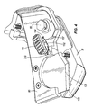
- Fig. 2 is an enlarged perspective view of a portion of the cutter of Fig. 1 ;
- Fig. 3 is an enlarged perspective view of another portion of the cutter of Fig. 1 ;
- Fig. 4 is partially broken away perspective view of a portion of the cutter of Fig. 1 ;
- Fig. 5 is a section view of a portion of the cutter taken along line 5-5 of Fig. 1 ;
- Fig. 6 is a section view of a portion of the cutter taken along line 6-6 of Fig. 1 ;
- Fig. 7 is an exploded perspective view of the cutter of Fig. 1 .
- Fig. 1 illustrates a cutter 10 that is well-suited to the task of cutting tubes.
- the cutter 10 is well-suited to cutting plastic tubes such as PEX (cross-linked polyethylene) tubes.
- the cutter 10 includes a first handle 15 (sometimes referred to as an outside handle) and a second handle 20 (sometimes referred to as an inside handle).
- the first handle 15 includes a first grip portion 25 disposed at one end of the first handle 15 and a first head portion 30 disposed at the opposite end of the first handle 15.
- the first grip portion 25 is preferably curved to better fit into a user's hand. However, straight portions or different ergonomically-shaped first grip portions 25 could also be employed.
- a soft grip 35 is positioned over a portion of the first grip portion 25 to improve the grip between the user and the cutter 10.
- the soft grip 35 is formed as a separate piece and is then positioned on the first grip portion 25.
- the soft grip 35 is over molded or co-molded into position. Of course, other constructions form the soft grip 35 and position the soft grip 35 using other processes and methods.
- the first head portion 30 includes two spaced apart side portions 40 that cooperate to define a space 45 between the side portions 40.
- the side portions 40 each include an arcuate aperture 50 that in some constructions is semi-circular.
- a smaller pivot aperture 55 extends through the first head portion 30 and defines a first pivot axis 60.
- a first end of the first head portion 30 includes a concave surface 65 that defines a slot 70 or opening (shown in Fig. 2 ).
- the slot 70 extends in a slitting direction 75 and the concave surface 65 is preferably arranged such that the slitting direction 75 is parallel to an axis defined by the focus or center of the concave surface 65.
- the slitting direction 75 is also normal to the first pivot axis 60.
- the first head portion 30 and the first grip portion 25 are formed as a single piece to improve the strength of the first handle 15.
- a suitable attachment means e.g., welding, soldering, brazing, co-molding, fasteners, adhesives, etc.
- the second handle 20 includes a second grip portion 80 and a second head portion 85.
- the second grip portion 80 is similar to the first grip portion 25 of the first handle 15 and will not be described in detail.
- the second grip portion 80 and the second head portion 85 can be formed as one piece or multiple pieces in much the same way as has been described with regard to the first handle 15 and will not be described in detail.
- the second head portion 85 includes a second arcuate aperture 90 that in preferred constructions is semicircular.
- a slot 95 is formed in a portion of a wall 100 that defines the second arcuate aperture 90 and is sized to receive a portion of a cutting blade 105.
- the cutting blade 105 fits within the slot 95 and is attached to the second head portion 85 using two fasteners 110.
- the second head portion 85 also includes a pivot aperture 115 (shown in Fig. 7 ) that extends along the pivot axis 60.
- the second head portion 85 is sized to fit within the space 45 between the first side portion 40 and the second side portion 40 of the first head 30.
- the first pivot aperture 55 aligns with the second pivot aperture 115.
- a pin or fastener 120 passes through the pivot apertures 55, 115 to pivotally connect the first handle 15 and the second handle 20. Once connected, the first grip portion 25 and the second grip portion 80 cooperate to define a comfortable and convenient grip for a user.
- the cutter 10 of Fig. 1 is movable between a closed or slitting position (shown in Figs. 1 and 2 ) and an open position.
- a biasing member 121 (shown in Fig. 7 ) is positioned to bias the first handle 15 and the second handle 20 toward the open position.
- Suitable biasing members 121 could include springs (e.g., coil, leaf, torsional, etc.) or other biasing members that function to move the handles 15, 20 toward the open position.
- the first grip portion 25 and the second grip portion 80 are separated, thereby separating the first head portion 30 and the second head portion 85.
- the arcuate apertures 50, 90 are spaced apart from one another a distance sufficient for the positioning of a tube within the arcuate apertures 50, 90.
- the tube can rest against the aperture walls formed in the first side portion 40 and the second side portion 40.
- a bottom cutting edge 125 of the blade 105 contacts the tube and begins cutting the tube.
- the blade 105 In the closed position, the blade 105 has moved through the tube and the cutting edge 125 of the blade 105 is disposed beneath the arcuate apertures 50 of the first head portion 30 and in the space 45 between the first side portion 40 and the second side portion 40.
- the cutting edge 125 includes a first corner, a second corner, and a point in the middle and is therefore substantially V-shaped.
- other constructions could use straight cutting edges that are normal to the tube or angled with respect to the tube, curved blades, or other suitable shapes.
- a slitting portion 130 of the cutting edge 125 of the blade 105 extends through the slot 70 defined in the concave surface 65 of the first head portion 30.
- the cutter 10 can be positioned against a tube to slit the tube in a lengthwise direction.
- the concave surface 65 engages the outer surface of the tube being slit to improve the contact between the tube and the cutter 10.
- the slitting portion 130 is at least partially defined by the first corner of the cutting edge 125.
- Figs. 3-4 illustrate a locking mechanism 135 that is suited to locking the first handle 15 and the second handle 20 in the slitting position.
- the first head portion 30 includes an external channel 140 that receives a slider 145.
- the channel is substantially rectangular and extends in a substantially linear direction.
- the slider 145 is movable between a locked position in which the first handle 15 and the second handle 20 are inhibited from moving with respect to one another and an unlocked position in which the first handle 15 and the second handle 20 are substantially free to pivot about the pivot axis 60.
- the slider 145 includes a pin 150 that extends through the external channel 140 and into the second head portion 85.
- the pin 150 has a groove 151 that runs around an outer perimeter of the pin 150.
- a spring plate 152 is disposed, and preferably fixedly attached to the pin 150, and is secured to the pin 150 by an e-clip 153.
- the spring plate 152 includes two legs that extend from the pin 150 (when the spring plate 152 is attached to the pin 150) in a cantilever fashion and define two protrusions 154.
- the pin 150 is cuboidal, with other shapes being possible.
- the protrusions 154 contact a wall 155, the wall 155 defining a side of the external channel 140.
- the interference between the wall 155 and the protrusions 154 serves to inhibit the slider 145 from leaving the locked position while still allowing the pin 150 and protrusions 154 to move within the channel 140.
- the user may move the slider 145 out of the locked position by applying a force to the slider 145 (in a direction away from the blade 105), thus forcing the protrusions 154 to move along the wall 155 and onto an internal surface 160 of the first head portion 30.
- the protrusions 154 After moving along the internal surface 160, the protrusions 154 will engage an indentation 165 formed in the first head portion 30 that cooperates with the protrusions 154 to bias the slider 145 into the unlocked position and inhibit movement out of that position.
- the spring plate 152, and more specifically the protrusions 154 cooperates with the first head portion 30 to bias the pin 150 into one of the locked position and the unlocked position
- the slider 145 serves to place the cutter 10 in the locked position or the unlocked position.
- the first handle 15 and second handle 20 are biased away from each other by the biasing member 121, however, the biasing member 121 is sized and configured so that the user may overcome the biasing force so that the cutter 10 may be operated in a scissors motion.
- the second head portion 85 includes a first channel 205 and a second channel 157 that cooperate with one another to define a V-shaped channel 210.
- the first channel 205 is substantially rectangular or linear and defines a substantially linearly extending leg and the second channel 157 is arcuate and defines a substantially arcuate leg.
- the second channel 157 is arranged such that it curves around a center 215 that resides on or near the pivot axis 60 of the first handle 15 and the second handle 20.
- the first channel 205 substantially overlies the channel 140 formed in the first head portion 30.
- the slider 145 and the pin 150 are free to move along the entire length of the first channel 205.
- the pin 150 When the pin 150 is moved toward the cutting blade 105 as illustrated in Fig. 6 , it moves out of the space defined by the second channel 157 such that the walls that define the first channel 205 inhibit movement of the pin 150 around the pivot axis 60. If the pin 150 cannot move around the pivot axis 60, the handles 15, 20 cannot pivot about each other and the device is fixed in the locked position. When the user moves the slider 145 away from the cutting blade 105 and into the second channel 157, the pin 150 becomes free to move about the pivot axis 60, thereby freeing the handles 15, 20 for movement to the open position.
- the first handle 15 and second handle 20 are held proximate to each other, as seen in Fig. 1 , and the slider 145 inhibits the first handle 15 and second handle 20 from moving relative to one another.
- the cutter is in the slitting position so that the slitting portion 130 is disposed as seen in Fig. 1 so that a user may slice a tube as has been described.
Landscapes
- Life Sciences & Earth Sciences (AREA)
- Forests & Forestry (AREA)
- Engineering & Computer Science (AREA)
- Mechanical Engineering (AREA)
- Knives (AREA)
- Scissors And Nippers (AREA)
Applications Claiming Priority (1)
| Application Number | Priority Date | Filing Date | Title |
|---|---|---|---|
| US40892310P | 2010-11-01 | 2010-11-01 |
Publications (3)
| Publication Number | Publication Date |
|---|---|
| EP2447019A2 true EP2447019A2 (fr) | 2012-05-02 |
| EP2447019A3 EP2447019A3 (fr) | 2012-07-18 |
| EP2447019B1 EP2447019B1 (fr) | 2018-03-21 |
Family
ID=45463407
Family Applications (1)
| Application Number | Title | Priority Date | Filing Date |
|---|---|---|---|
| EP11250880.9A Active EP2447019B1 (fr) | 2010-11-01 | 2011-11-01 | Découpeur transversal et longitudinal de tuyaux avec verrouillage |
Country Status (3)
| Country | Link |
|---|---|
| US (1) | US20120102752A1 (fr) |
| EP (1) | EP2447019B1 (fr) |
| CA (2) | CA2848966C (fr) |
Cited By (4)
| Publication number | Priority date | Publication date | Assignee | Title |
|---|---|---|---|---|
| CN106109002A (zh) * | 2016-07-20 | 2016-11-16 | 上海景堂医疗器械有限公司 | 弧形剪断钳 |
| DE202016106176U1 (de) * | 2016-11-04 | 2018-02-08 | Rehau Ag + Co | Rohrschere |
| WO2019016194A3 (fr) * | 2017-07-17 | 2019-04-04 | Gustav Klauke Gmbh | Dispositif de travail pour couper une piece |
| TWI774593B (zh) * | 2021-10-25 | 2022-08-11 | 鄭人豪 | 切管裝置 |
Families Citing this family (14)
| Publication number | Priority date | Publication date | Assignee | Title |
|---|---|---|---|---|
| US20100186235A1 (en) * | 2009-01-26 | 2010-07-29 | Eric Davis Schwartz | Portable battery operated pipe cutter |
| US8904648B2 (en) * | 2012-08-10 | 2014-12-09 | Tektro Technology Corporation | Hydraulic hose cutting device |
| US9707691B2 (en) * | 2013-01-14 | 2017-07-18 | RL Tools, L.L.C. | Conduit cutting tools and conduit cutting tool operational methods |
| USD750947S1 (en) | 2013-05-09 | 2016-03-08 | Oetiker Tool Corporation | Cutting tool |
| US11027399B2 (en) | 2015-04-02 | 2021-06-08 | Milwaukee Electric Tool Corporation | Hand tool such as a wire stripper or combination pliers |
| USD809363S1 (en) * | 2016-04-01 | 2018-02-06 | Fiskars Brands, Inc. | Cutting tool |
| TWM534671U (zh) * | 2016-09-23 | 2017-01-01 | Hanlong Industrial Co Ltd | 管剪 |
| USD896606S1 (en) | 2017-05-04 | 2020-09-22 | Siang Syuan Fu Enterprise Co., Ltd. | Cutter |
| US10486248B2 (en) | 2017-06-08 | 2019-11-26 | Greenlee Tools, Inc. | Cutting tool |
| US20200016670A1 (en) * | 2018-07-15 | 2020-01-16 | Hsin-Ping Wang | Plastic tube cutter |
| CN115488932B (zh) * | 2021-06-18 | 2024-11-15 | 杭州巨星科技股份有限公司 | 多功能管子割刀 |
| USD998439S1 (en) * | 2022-01-06 | 2023-09-12 | Siang Syuan Fu Enterprise Co., Ltd. | Cutter |
| USD999040S1 (en) * | 2022-01-06 | 2023-09-19 | Siang Syuan Fu Enterprise Co., Ltd. | Cutter |
| KR102887630B1 (ko) * | 2023-12-15 | 2025-11-19 | 장신혁 | 손 끼임 방지용 파이프 절단기 |
Family Cites Families (38)
| Publication number | Priority date | Publication date | Assignee | Title |
|---|---|---|---|---|
| US2235342A (en) * | 1939-11-07 | 1941-03-18 | Thomas P Turner | Tool for splitting and hulling peas |
| US2329805A (en) * | 1942-12-30 | 1943-09-21 | Sr Fred G Wilson | Electric cable cutter |
| US2817255A (en) * | 1954-12-20 | 1957-12-24 | Lormeau Rene | Wire stripping tool |
| US2835031A (en) * | 1956-10-29 | 1958-05-20 | Jr Robert F Cook | Electric cable insulation cutter |
| US3238618A (en) * | 1963-12-10 | 1966-03-08 | Jr Robert F Cook | Electric cable insulation cutter |
| US3624901A (en) * | 1969-08-26 | 1971-12-07 | Walter G Pettit | Wire stripper and cutter |
| US3777397A (en) * | 1972-05-30 | 1973-12-11 | W Johnson | Shielded cable stripper |
| US4001934A (en) * | 1975-07-10 | 1977-01-11 | Bell Robert G | Coin roll cutter |
| US4083105A (en) * | 1975-09-05 | 1978-04-11 | Ideal Industries, Inc. | Wire strippers |
| US4026017A (en) * | 1975-11-14 | 1977-05-31 | Howard Kay Arnold | Cable tool |
| USD266736S (en) * | 1980-08-01 | 1982-11-02 | Robertson Duane D | Cutting tool for flexible plastic conduit |
| US4434555A (en) * | 1982-03-25 | 1984-03-06 | Kurt Stoll | Cutter for flexible pipes |
| US4536957A (en) * | 1982-04-14 | 1985-08-27 | Walter Britton | Splitter for electrical cable |
| US4835862A (en) * | 1986-07-25 | 1989-06-06 | Phillips Daniel B | Coaxial cable cutter/stripper |
| US4932124A (en) * | 1989-05-25 | 1990-06-12 | Tai Young Pyun | Tool for cutting and stripping armored electric cables |
| DE4395696T1 (de) * | 1992-11-09 | 1995-10-19 | Raymond Drummond Thomas | Verbesserungen für oder im Zusammenhang mit Schneidwerkzeugen |
| US5367774A (en) * | 1993-06-29 | 1994-11-29 | Fiskars Inc. | Resilient lock for a hand tool |
| US5561903A (en) * | 1994-12-15 | 1996-10-08 | Ben Hughes Communication Products Company | Messenger removal tool |
| US5732471A (en) * | 1996-11-14 | 1998-03-31 | Applied Power Inc. | Wire stripper with integral cable sheath cutter |
| US5887346A (en) * | 1997-07-23 | 1999-03-30 | Ameron International Corporation | Co-axial flexible pipe jacket cutter |
| US6088920A (en) * | 1998-11-03 | 2000-07-18 | Midwest Tool And Cutlery Company | Cable cutter with insert blades |
| NL1010596C1 (nl) * | 1998-11-19 | 2000-05-22 | Petrus Van Empelen | Inrichting voor het aanbrengen van een langssnede in een langgerekt voedselproduct. |
| US6170230B1 (en) * | 1998-12-04 | 2001-01-09 | Automed Technologies, Inc. | Medication collecting system |
| US6148521A (en) * | 1998-12-11 | 2000-11-21 | At&T Corp. | Method and apparatus for slitting optical power ground wires |
| USD423895S (en) * | 1999-03-03 | 2000-05-02 | Super-Ego Tools, S.A. | Shears for cutting plastic tubes |
| US6282995B1 (en) * | 2000-09-11 | 2001-09-04 | Shu Sen Lin | Plier tool having quickly attachable tool members |
| US6370780B1 (en) * | 2000-12-29 | 2002-04-16 | Duane D. Robertson | Spring-biased cutting tool for plastic pipes |
| US6698099B2 (en) * | 2001-11-30 | 2004-03-02 | Ronan Tools, Inc. | Convertible knife |
| US20050150115A1 (en) * | 2002-05-15 | 2005-07-14 | Hanna Robert J. | Knife with partially exposed blade when closed |
| US20030213133A1 (en) * | 2002-05-15 | 2003-11-20 | Hanna Robert J. | Knife with partially exposed blade when closed |
| FR2867406B1 (fr) * | 2004-03-10 | 2007-04-27 | Pierre Grehal Et Cie Ets | Pince pour decoupe des profiles |
| US6964099B1 (en) * | 2004-08-19 | 2005-11-15 | Min Zheng Zeng | Gardening shears having two pruning effects |
| US7462167B2 (en) * | 2005-01-26 | 2008-12-09 | Thomas Medical Products, Inc. | Catheter sheath slitter and method of use |
| US7185409B1 (en) * | 2005-02-17 | 2007-03-06 | Michael Myers | Installation tool for irrigation emitter barbs with cutter |
| US7346986B2 (en) * | 2006-02-23 | 2008-03-25 | Rain Bird Corporation | Cutting tool for flexible conduit |
| US7549226B2 (en) * | 2006-07-12 | 2009-06-23 | Duane D. Robertson | Self-locking cutting tool for plastic pipes |
| TWI357701B (en) * | 2008-01-11 | 2012-02-01 | Nusharp Inc | Auxiliary structure of a skinning knife |
| US7913394B2 (en) * | 2008-04-15 | 2011-03-29 | Hager Gregory L | Cable sheath splitter |
-
2011
- 2011-11-01 CA CA2848966A patent/CA2848966C/fr active Active
- 2011-11-01 CA CA2756869A patent/CA2756869C/fr active Active
- 2011-11-01 US US13/286,328 patent/US20120102752A1/en not_active Abandoned
- 2011-11-01 EP EP11250880.9A patent/EP2447019B1/fr active Active
Non-Patent Citations (1)
| Title |
|---|
| None |
Cited By (6)
| Publication number | Priority date | Publication date | Assignee | Title |
|---|---|---|---|---|
| CN106109002A (zh) * | 2016-07-20 | 2016-11-16 | 上海景堂医疗器械有限公司 | 弧形剪断钳 |
| CN106109002B (zh) * | 2016-07-20 | 2018-06-19 | 上海景堂医疗器械有限公司 | 弧形剪断钳 |
| DE202016106176U1 (de) * | 2016-11-04 | 2018-02-08 | Rehau Ag + Co | Rohrschere |
| WO2019016194A3 (fr) * | 2017-07-17 | 2019-04-04 | Gustav Klauke Gmbh | Dispositif de travail pour couper une piece |
| US11684984B2 (en) | 2017-07-17 | 2023-06-27 | Gustav Klauke Gmbh | Tool for cutting a workpiece |
| TWI774593B (zh) * | 2021-10-25 | 2022-08-11 | 鄭人豪 | 切管裝置 |
Also Published As
| Publication number | Publication date |
|---|---|
| CA2756869C (fr) | 2014-07-08 |
| CA2848966C (fr) | 2015-08-18 |
| EP2447019A3 (fr) | 2012-07-18 |
| CA2848966A1 (fr) | 2012-05-01 |
| EP2447019B1 (fr) | 2018-03-21 |
| US20120102752A1 (en) | 2012-05-03 |
| CA2756869A1 (fr) | 2012-05-01 |
Similar Documents
| Publication | Publication Date | Title |
|---|---|---|
| EP2447019B1 (fr) | Découpeur transversal et longitudinal de tuyaux avec verrouillage | |
| US7080455B1 (en) | Handheld kitchen scissor/knife appliance | |
| US5802942A (en) | Paper trimmer | |
| US10144139B2 (en) | Utility knife | |
| US20070169353A1 (en) | Method and apparatus for a quick blade release folding utility knife | |
| US20130091713A1 (en) | Scissors structure with adjustable opening | |
| US20100212162A1 (en) | Utility cutter with a non-tool blade changer | |
| US20100058914A1 (en) | Knife connector | |
| US6334255B1 (en) | Shears capable of cutting simultaneously a plurality of objects of different dimensions and profiles | |
| US20110185577A1 (en) | Hand-held cutter with an auxiliary handle for performing an initial cutting operation | |
| CN102126224A (zh) | 具自动回弹功能的刀具 | |
| US20120017441A1 (en) | Combination dual blade knife | |
| US7549226B2 (en) | Self-locking cutting tool for plastic pipes | |
| US6527157B1 (en) | Stapler with punching unit | |
| US20150101197A1 (en) | Safety Knife | |
| US20070151108A1 (en) | Safety razor apparatus having an adjustable guiding member | |
| CN106493756B (zh) | 带切割器功能的剪刀 | |
| KR101585879B1 (ko) | 가이드가 구비된 가위 | |
| US20060200913A1 (en) | Plier handle | |
| US20130014392A1 (en) | Cutting tool with adjustable cutting angle | |
| US20160106265A1 (en) | Spatula Knife Utensil | |
| JPH0744297Y2 (ja) | 切断具 | |
| AU2021101974A4 (en) | Multi - Purpose Line Trimmer Cutting Tool | |
| JP2017080059A (ja) | カバー付き清掃具のカバー開閉方法及びカバー付き清掃具 | |
| KR101905043B1 (ko) | 날의 선택적 사용이 가능한 가위 |
Legal Events
| Date | Code | Title | Description |
|---|---|---|---|
| PUAI | Public reference made under article 153(3) epc to a published international application that has entered the european phase |
Free format text: ORIGINAL CODE: 0009012 |
|
| AK | Designated contracting states |
Kind code of ref document: A2 Designated state(s): AL AT BE BG CH CY CZ DE DK EE ES FI FR GB GR HR HU IE IS IT LI LT LU LV MC MK MT NL NO PL PT RO RS SE SI SK SM TR |
|
| AX | Request for extension of the european patent |
Extension state: BA ME |
|
| PUAL | Search report despatched |
Free format text: ORIGINAL CODE: 0009013 |
|
| AK | Designated contracting states |
Kind code of ref document: A3 Designated state(s): AL AT BE BG CH CY CZ DE DK EE ES FI FR GB GR HR HU IE IS IT LI LT LU LV MC MK MT NL NO PL PT RO RS SE SI SK SM TR |
|
| AX | Request for extension of the european patent |
Extension state: BA ME |
|
| RIC1 | Information provided on ipc code assigned before grant |
Ipc: B26D 3/00 20060101ALI20120612BHEP Ipc: B26D 3/16 20060101AFI20120612BHEP |
|
| 17P | Request for examination filed |
Effective date: 20130115 |
|
| 17Q | First examination report despatched |
Effective date: 20150716 |
|
| GRAP | Despatch of communication of intention to grant a patent |
Free format text: ORIGINAL CODE: EPIDOSNIGR1 |
|
| INTG | Intention to grant announced |
Effective date: 20170927 |
|
| GRAS | Grant fee paid |
Free format text: ORIGINAL CODE: EPIDOSNIGR3 |
|
| GRAA | (expected) grant |
Free format text: ORIGINAL CODE: 0009210 |
|
| AK | Designated contracting states |
Kind code of ref document: B1 Designated state(s): AL AT BE BG CH CY CZ DE DK EE ES FI FR GB GR HR HU IE IS IT LI LT LU LV MC MK MT NL NO PL PT RO RS SE SI SK SM TR |
|
| REG | Reference to a national code |
Ref country code: GB Ref legal event code: FG4D |
|
| REG | Reference to a national code |
Ref country code: CH Ref legal event code: EP |
|
| REG | Reference to a national code |
Ref country code: AT Ref legal event code: REF Ref document number: 980601 Country of ref document: AT Kind code of ref document: T Effective date: 20180415 |
|
| REG | Reference to a national code |
Ref country code: IE Ref legal event code: FG4D |
|
| REG | Reference to a national code |
Ref country code: DE Ref legal event code: R096 Ref document number: 602011046654 Country of ref document: DE |
|
| REG | Reference to a national code |
Ref country code: NL Ref legal event code: MP Effective date: 20180321 |
|
| PG25 | Lapsed in a contracting state [announced via postgrant information from national office to epo] |
Ref country code: CY Free format text: LAPSE BECAUSE OF FAILURE TO SUBMIT A TRANSLATION OF THE DESCRIPTION OR TO PAY THE FEE WITHIN THE PRESCRIBED TIME-LIMIT Effective date: 20180321 Ref country code: NO Free format text: LAPSE BECAUSE OF FAILURE TO SUBMIT A TRANSLATION OF THE DESCRIPTION OR TO PAY THE FEE WITHIN THE PRESCRIBED TIME-LIMIT Effective date: 20180621 Ref country code: HR Free format text: LAPSE BECAUSE OF FAILURE TO SUBMIT A TRANSLATION OF THE DESCRIPTION OR TO PAY THE FEE WITHIN THE PRESCRIBED TIME-LIMIT Effective date: 20180321 Ref country code: LT Free format text: LAPSE BECAUSE OF FAILURE TO SUBMIT A TRANSLATION OF THE DESCRIPTION OR TO PAY THE FEE WITHIN THE PRESCRIBED TIME-LIMIT Effective date: 20180321 Ref country code: FI Free format text: LAPSE BECAUSE OF FAILURE TO SUBMIT A TRANSLATION OF THE DESCRIPTION OR TO PAY THE FEE WITHIN THE PRESCRIBED TIME-LIMIT Effective date: 20180321 |
|
| REG | Reference to a national code |
Ref country code: LT Ref legal event code: MG4D |
|
| REG | Reference to a national code |
Ref country code: AT Ref legal event code: MK05 Ref document number: 980601 Country of ref document: AT Kind code of ref document: T Effective date: 20180321 |
|
| PG25 | Lapsed in a contracting state [announced via postgrant information from national office to epo] |
Ref country code: RS Free format text: LAPSE BECAUSE OF FAILURE TO SUBMIT A TRANSLATION OF THE DESCRIPTION OR TO PAY THE FEE WITHIN THE PRESCRIBED TIME-LIMIT Effective date: 20180321 Ref country code: GR Free format text: LAPSE BECAUSE OF FAILURE TO SUBMIT A TRANSLATION OF THE DESCRIPTION OR TO PAY THE FEE WITHIN THE PRESCRIBED TIME-LIMIT Effective date: 20180622 Ref country code: BG Free format text: LAPSE BECAUSE OF FAILURE TO SUBMIT A TRANSLATION OF THE DESCRIPTION OR TO PAY THE FEE WITHIN THE PRESCRIBED TIME-LIMIT Effective date: 20180621 Ref country code: LV Free format text: LAPSE BECAUSE OF FAILURE TO SUBMIT A TRANSLATION OF THE DESCRIPTION OR TO PAY THE FEE WITHIN THE PRESCRIBED TIME-LIMIT Effective date: 20180321 Ref country code: SE Free format text: LAPSE BECAUSE OF FAILURE TO SUBMIT A TRANSLATION OF THE DESCRIPTION OR TO PAY THE FEE WITHIN THE PRESCRIBED TIME-LIMIT Effective date: 20180321 |
|
| PG25 | Lapsed in a contracting state [announced via postgrant information from national office to epo] |
Ref country code: ES Free format text: LAPSE BECAUSE OF FAILURE TO SUBMIT A TRANSLATION OF THE DESCRIPTION OR TO PAY THE FEE WITHIN THE PRESCRIBED TIME-LIMIT Effective date: 20180321 Ref country code: NL Free format text: LAPSE BECAUSE OF FAILURE TO SUBMIT A TRANSLATION OF THE DESCRIPTION OR TO PAY THE FEE WITHIN THE PRESCRIBED TIME-LIMIT Effective date: 20180321 Ref country code: AL Free format text: LAPSE BECAUSE OF FAILURE TO SUBMIT A TRANSLATION OF THE DESCRIPTION OR TO PAY THE FEE WITHIN THE PRESCRIBED TIME-LIMIT Effective date: 20180321 Ref country code: PL Free format text: LAPSE BECAUSE OF FAILURE TO SUBMIT A TRANSLATION OF THE DESCRIPTION OR TO PAY THE FEE WITHIN THE PRESCRIBED TIME-LIMIT Effective date: 20180321 Ref country code: RO Free format text: LAPSE BECAUSE OF FAILURE TO SUBMIT A TRANSLATION OF THE DESCRIPTION OR TO PAY THE FEE WITHIN THE PRESCRIBED TIME-LIMIT Effective date: 20180321 Ref country code: EE Free format text: LAPSE BECAUSE OF FAILURE TO SUBMIT A TRANSLATION OF THE DESCRIPTION OR TO PAY THE FEE WITHIN THE PRESCRIBED TIME-LIMIT Effective date: 20180321 Ref country code: IT Free format text: LAPSE BECAUSE OF FAILURE TO SUBMIT A TRANSLATION OF THE DESCRIPTION OR TO PAY THE FEE WITHIN THE PRESCRIBED TIME-LIMIT Effective date: 20180321 |
|
| PG25 | Lapsed in a contracting state [announced via postgrant information from national office to epo] |
Ref country code: SK Free format text: LAPSE BECAUSE OF FAILURE TO SUBMIT A TRANSLATION OF THE DESCRIPTION OR TO PAY THE FEE WITHIN THE PRESCRIBED TIME-LIMIT Effective date: 20180321 Ref country code: CZ Free format text: LAPSE BECAUSE OF FAILURE TO SUBMIT A TRANSLATION OF THE DESCRIPTION OR TO PAY THE FEE WITHIN THE PRESCRIBED TIME-LIMIT Effective date: 20180321 Ref country code: SM Free format text: LAPSE BECAUSE OF FAILURE TO SUBMIT A TRANSLATION OF THE DESCRIPTION OR TO PAY THE FEE WITHIN THE PRESCRIBED TIME-LIMIT Effective date: 20180321 Ref country code: AT Free format text: LAPSE BECAUSE OF FAILURE TO SUBMIT A TRANSLATION OF THE DESCRIPTION OR TO PAY THE FEE WITHIN THE PRESCRIBED TIME-LIMIT Effective date: 20180321 |
|
| PG25 | Lapsed in a contracting state [announced via postgrant information from national office to epo] |
Ref country code: PT Free format text: LAPSE BECAUSE OF FAILURE TO SUBMIT A TRANSLATION OF THE DESCRIPTION OR TO PAY THE FEE WITHIN THE PRESCRIBED TIME-LIMIT Effective date: 20180723 |
|
| REG | Reference to a national code |
Ref country code: DE Ref legal event code: R097 Ref document number: 602011046654 Country of ref document: DE |
|
| PLBE | No opposition filed within time limit |
Free format text: ORIGINAL CODE: 0009261 |
|
| STAA | Information on the status of an ep patent application or granted ep patent |
Free format text: STATUS: NO OPPOSITION FILED WITHIN TIME LIMIT |
|
| PG25 | Lapsed in a contracting state [announced via postgrant information from national office to epo] |
Ref country code: DK Free format text: LAPSE BECAUSE OF FAILURE TO SUBMIT A TRANSLATION OF THE DESCRIPTION OR TO PAY THE FEE WITHIN THE PRESCRIBED TIME-LIMIT Effective date: 20180321 |
|
| 26N | No opposition filed |
Effective date: 20190102 |
|
| PG25 | Lapsed in a contracting state [announced via postgrant information from national office to epo] |
Ref country code: SI Free format text: LAPSE BECAUSE OF FAILURE TO SUBMIT A TRANSLATION OF THE DESCRIPTION OR TO PAY THE FEE WITHIN THE PRESCRIBED TIME-LIMIT Effective date: 20180321 |
|
| REG | Reference to a national code |
Ref country code: CH Ref legal event code: PL |
|
| PG25 | Lapsed in a contracting state [announced via postgrant information from national office to epo] |
Ref country code: MC Free format text: LAPSE BECAUSE OF FAILURE TO SUBMIT A TRANSLATION OF THE DESCRIPTION OR TO PAY THE FEE WITHIN THE PRESCRIBED TIME-LIMIT Effective date: 20180321 Ref country code: LU Free format text: LAPSE BECAUSE OF NON-PAYMENT OF DUE FEES Effective date: 20181101 |
|
| REG | Reference to a national code |
Ref country code: BE Ref legal event code: MM Effective date: 20181130 |
|
| REG | Reference to a national code |
Ref country code: IE Ref legal event code: MM4A |
|
| PG25 | Lapsed in a contracting state [announced via postgrant information from national office to epo] |
Ref country code: CH Free format text: LAPSE BECAUSE OF NON-PAYMENT OF DUE FEES Effective date: 20181130 Ref country code: LI Free format text: LAPSE BECAUSE OF NON-PAYMENT OF DUE FEES Effective date: 20181130 |
|
| PG25 | Lapsed in a contracting state [announced via postgrant information from national office to epo] |
Ref country code: FR Free format text: LAPSE BECAUSE OF NON-PAYMENT OF DUE FEES Effective date: 20181130 Ref country code: IE Free format text: LAPSE BECAUSE OF NON-PAYMENT OF DUE FEES Effective date: 20181101 |
|
| PG25 | Lapsed in a contracting state [announced via postgrant information from national office to epo] |
Ref country code: BE Free format text: LAPSE BECAUSE OF NON-PAYMENT OF DUE FEES Effective date: 20181130 |
|
| PG25 | Lapsed in a contracting state [announced via postgrant information from national office to epo] |
Ref country code: MT Free format text: LAPSE BECAUSE OF NON-PAYMENT OF DUE FEES Effective date: 20181101 |
|
| PG25 | Lapsed in a contracting state [announced via postgrant information from national office to epo] |
Ref country code: TR Free format text: LAPSE BECAUSE OF FAILURE TO SUBMIT A TRANSLATION OF THE DESCRIPTION OR TO PAY THE FEE WITHIN THE PRESCRIBED TIME-LIMIT Effective date: 20180321 |
|
| PG25 | Lapsed in a contracting state [announced via postgrant information from national office to epo] |
Ref country code: MK Free format text: LAPSE BECAUSE OF NON-PAYMENT OF DUE FEES Effective date: 20180321 Ref country code: HU Free format text: LAPSE BECAUSE OF FAILURE TO SUBMIT A TRANSLATION OF THE DESCRIPTION OR TO PAY THE FEE WITHIN THE PRESCRIBED TIME-LIMIT; INVALID AB INITIO Effective date: 20111101 |
|
| PG25 | Lapsed in a contracting state [announced via postgrant information from national office to epo] |
Ref country code: IS Free format text: LAPSE BECAUSE OF FAILURE TO SUBMIT A TRANSLATION OF THE DESCRIPTION OR TO PAY THE FEE WITHIN THE PRESCRIBED TIME-LIMIT Effective date: 20180721 |
|
| P01 | Opt-out of the competence of the unified patent court (upc) registered |
Effective date: 20230524 |
|
| PGFP | Annual fee paid to national office [announced via postgrant information from national office to epo] |
Ref country code: DE Payment date: 20251128 Year of fee payment: 15 |
|
| PGFP | Annual fee paid to national office [announced via postgrant information from national office to epo] |
Ref country code: GB Payment date: 20251127 Year of fee payment: 15 |