EP2447149A1 - Schiff mit einem redundanten Stromversorgungssystem, das dem Backbord- und dem Steuerbordantriebssystem gemein ist - Google Patents
Schiff mit einem redundanten Stromversorgungssystem, das dem Backbord- und dem Steuerbordantriebssystem gemein ist Download PDFInfo
- Publication number
- EP2447149A1 EP2447149A1 EP11306382A EP11306382A EP2447149A1 EP 2447149 A1 EP2447149 A1 EP 2447149A1 EP 11306382 A EP11306382 A EP 11306382A EP 11306382 A EP11306382 A EP 11306382A EP 2447149 A1 EP2447149 A1 EP 2447149A1
- Authority
- EP
- European Patent Office
- Prior art keywords
- ship
- power
- longitudinal
- power supply
- network
- Prior art date
- Legal status (The legal status is an assumption and is not a legal conclusion. Google has not performed a legal analysis and makes no representation as to the accuracy of the status listed.)
- Granted
Links
Images

Classifications
-
- B—PERFORMING OPERATIONS; TRANSPORTING
- B63—SHIPS OR OTHER WATERBORNE VESSELS; RELATED EQUIPMENT
- B63H—MARINE PROPULSION OR STEERING
- B63H21/00—Use of propulsion power plant or units on vessels
- B63H21/21—Control means for engine or transmission, specially adapted for use on marine vessels
-
- B—PERFORMING OPERATIONS; TRANSPORTING
- B63—SHIPS OR OTHER WATERBORNE VESSELS; RELATED EQUIPMENT
- B63H—MARINE PROPULSION OR STEERING
- B63H23/00—Transmitting power from propulsion power plant to propulsive elements
- B63H23/22—Transmitting power from propulsion power plant to propulsive elements with non-mechanical gearing
- B63H23/24—Transmitting power from propulsion power plant to propulsive elements with non-mechanical gearing electric
-
- H—ELECTRICITY
- H02—GENERATION; CONVERSION OR DISTRIBUTION OF ELECTRIC POWER
- H02J—ELECTRIC POWER NETWORKS; CIRCUIT ARRANGEMENTS OR SYSTEMS FOR SUPPLYING OR DISTRIBUTING ELECTRIC POWER; SYSTEMS FOR STORING ELECTRIC ENERGY
- H02J2105/00—Networks for supplying or distributing electric power characterised by their spatial reach or by the load
- H02J2105/30—Networks for supplying or distributing electric power characterised by their spatial reach or by the load the load networks being external to vehicles, i.e. exchanging power with vehicles
- H02J2105/31—Networks for supplying or distributing electric power characterised by their spatial reach or by the load the load networks being external to vehicles, i.e. exchanging power with vehicles for ships or vessels
-
- H—ELECTRICITY
- H02—GENERATION; CONVERSION OR DISTRIBUTION OF ELECTRIC POWER
- H02J—ELECTRIC POWER NETWORKS; CIRCUIT ARRANGEMENTS OR SYSTEMS FOR SUPPLYING OR DISTRIBUTING ELECTRIC POWER; SYSTEMS FOR STORING ELECTRIC ENERGY
- H02J4/00—Circuit arrangements for mains or distribution networks not specified as AC or DC; Circuit arrangements for mains or distribution networks combining AC and DC sections or sub-networks
Definitions
- a vessel of the aforementioned type is known.
- the electricity network is an alternative network, and each power system comprises two frequency converters connected in parallel with the AC network.
- Each frequency converter has an electric power substantially equal to half of the maximum electric power of the corresponding electric motor.
- Each frequency converter of a respective power supply system is connected to the corresponding electric motor by means of an isolation device, the isolation device being able to electrically isolate this converter from the corresponding electric motor.
- the control of the power supply of the electric motors by the frequency converters and via the isolation device is relatively complex, the control of electric motors depending on several parameters such as the speed of the ship, the electric power supplied by each converter , the position of the isolation device of each converter.
- the object of the invention is to provide a vessel comprising a longitudinal propulsion chain for facilitating the supply of an electric motor driving a longitudinal thruster.
- the subject of the invention is a vessel of the aforementioned type, characterized in that it furthermore comprises an additional power supply system for the electric motors, the additional supply system comprising a single power output and being connected to the two electric motors via a switching device, the switching device being adapted to connect one or the other of the two electric motors to the single power output of the additional power supply system.
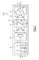
- a vessel 10 extending in a longitudinal direction X comprises an electrical network 12 and a longitudinal propulsion chain 14 connected to the electrical network.
- the longitudinal direction X represented on the figure 1 , extends from the stern to the bow of the ship 10.
- the electrical network 12 is an alternative network.
- the alternative electric network is, for example, a three-phase network.
- the alternative network 12 comprises a port bus 15 and a starboard bus 16 for circulating the electric current, four electric generators 18 connected to the circulation buses via first circuit breakers 20 and four diesel engines 22 for driving the electric generators.
- Two electric generators 18 are capable of delivering a three-phase current to the port bus 15, and two other electric generators 18 are able to deliver a three-phase current to the starboard bus 16.
- the electrical network 12 comprises a crossbar 24 of electrical connection between the port bus 15 and the starboard bus 16, and two second circuit breakers 26 connected between each end of the crossbar and the respective bus.
- the electrical network 12 also comprises two distribution transformers 28 adapted to deliver a low-voltage electrical current to a not shown secondary network, each distribution transformer 28 being connected to a respective bus 15, 16 via a third circuit breaker 30. .
- the electrical network 12 also includes fourth circuit breakers 32 connected between a respective bus 15, 16 and the propulsion chain 14.
- the longitudinal propulsion chain 14 comprises two longitudinal thrusters 34 capable of moving the ship in its longitudinal direction X and, for each longitudinal thruster, an electric motor 36 for driving the longitudinal thruster and a system 38 for supplying the electric motor.
- the longitudinal propulsion system further comprises an additional engine supply system 40 36 and a main switching device 42 connecting the additional power supply system to the two electric motors.
- the longitudinal propulsion chain 14 comprises, for example, a port 34 longitudinal thruster and a starboard longitudinal thruster 34, an port electric motor 36 and a starboard electric motor 36, as well as a port port power system 38 and a starboard propulsion system 38. 38 starboard power supply.
- the longitudinal propulsion chain 14 comprises a port chain and a starboard chain, each port, starboard chain comprising a thruster, an electric motor driving the thruster and a power supply system of the electric motor.
- each port and starboard chain includes port, starboard, and starboard port connections to the shore power network.
- the longitudinal propulsion chain 14 consists of the two longitudinal thrusters 34, the two electric drive motors 36, the three power supply systems 38, 40 of the electric motors, and the main switching device 42.
- the propulsion chain 14 comprises two auxiliary switching devices 44, each auxiliary switching device 44 connecting a respective power supply system 38 to an electric motor 36 corresponding, on the one hand, and a connection device 46 to a terrestrial electrical network, on the other hand.
- Each electric drive motor 36 is connected at the input of a corresponding longitudinal thruster.
- the electric motor 36 is, for example, a synchronous motor. In a variant, the electric motor 36 is asynchronous.
- Each power supply system 38 and the additional power supply system 40 comprise a power input 48, a power output 50 and a frequency converter 52, visible on the figure 2 , in order to vary the rotational speed of the corresponding electric motor 36.
- each power system 38 and the additional power supply system 40 is greater than or equal to the maximum electrical power of the corresponding electric motor 36.
- the supply systems 38, and the additional supply system 40 are, for example, identical.
- Each power supply system 38 is connected by its power input 48 to the electrical network 12 and by its power output 50 at the input of an electric motor 36 corresponding through the auxiliary switching device 44 corresponding.
- the supply system 38 port respectively starboard, is connected to the port bus 15 via the fourth circuit breaker 32 corresponding respectively to the starboard bus 16 via the fourth circuit breaker 32 corresponding.
- the additional power supply system 40 has a single power output 50, and is connected by its power input 48 to the port bus 15 via a fourth circuit breaker and to the starboard bus 16 via another fourth circuit breaker.
- the main switching device 42 and the auxiliary switching devices 44 each have three switching positions, namely a first electrical connection position, a second electrical connection position, and a third position of no electrical connection, as shown in FIG. the figure 1 .
- the main switching device 42 is adapted to connect one or the other of the two electric motors 36 to the single power output 50 of the additional power supply system.
- the first connection position of the main switching device corresponds, for example, to the electric motor 36 port, the second electrical connection position corresponding to the electric motor 36 starboard, and the last position corresponding to the case where the additional supply system n ' is not connected to one of the two electric motors 36.
- the first connection position of the auxiliary switching device 44 corresponds to the connection between the power system 38 and the respective electric motor 36.
- the second connection position corresponds to the connection between the power system 38 and the respective terrestrial network connection device 46 when the ship is docked, and the third position corresponds to a lack of electrical connection at the output of the system. power supply 38.
- the frequency converter 52 comprises a filter 54 connected to the input 48, a rectifier 56 connected at the output of the filter, an inverter 58 connected at the output of the rectifier via a continuous bus 60 and a device 62 for limiting the common-mode current able to circulate between the electrical network 12 and the corresponding electric motor 36.
- the output of the inverter 58 is connected to the power output 50.
- the frequency converter 52 does not include a voltage transformer connected between the input 48 and the rectifier 56.
- the frequency converter 52 is bi-directional in power, and is adapted to convert the current from the input 48 to the output 50, or vice versa from the output 50 to the input 48.
- the filter 54 of the power system comprises, for each phase of the alternating current supplied by the network 12, a first electromagnetic coil 64, one end of the first coil 64 being connected to the power input and the other end being connected to the input 72 of the rectifier.
- the filter 54 comprises a resistor 66 and a capacitor 67 connected in series between the end of the first coil connected to the power input and an electrical ground 68.
- the filter 54 comprises a second electromagnetic coil 69 and a capacitor 70 connected in series to the end of the first coil connected to the power input.
- the rectifier 56 is suitable for converting the alternating current supplied by the network 12 into a direct current delivered at the output of the rectifier.
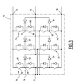
- the rectifier 56 is, for example, a bidirectional controlled bidirectional rectifier, also known as AFE (Active Front End), as shown in FIG. figure 3 . It comprises an input terminal 72 for each phase of the alternating current supplied by the network, two output terminals 74.
- the rectifier 56 is, for example, a three-phase rectifier and comprises three input terminals 72.
- the rectifier 56 is connected to the network 12 without the presence of a transformer between itself and the reciprocating network 12 in the exemplary embodiment of the figure 2 .
- the rectifier 56 has a neutral clamp type topology, also known as the Neutral Point Clamped (NPC) topology, and comprises a midpoint 75 between the two output terminals and two switching branches 76 for each phase of said alternating current.
- Each switching branch is connected between a respective input terminal 72 and the corresponding output terminal 74.
- Each switching branch 76 comprises, for example, two controllable electronic switches 78 connected in series and interconnected by an intermediate point 80.
- the intermediate point 80 of a switching branch 76 is connected to the point medium 75 through a first diode 82 connected in reverse, the intermediate point 80 of the other switching branch 76 being connected to the midpoint 75 via a second diode 84 connected in forward direction.
- Each controllable electronic switch 78 is, for example, bidirectional in current, and comprises a transistor 86 and a diode 88 connected in antiparallel of the transistor.
- Transistor 86 is, for example, an IGBT (Insulated Gate Bipolar Transistor) transistor.
- the rectifier 56 has a topology of the type controlled by the neutral, also called the NPP (Neutral Point Piloted) topology.
- the rectifier comprises a midpoint between the two output terminals, two extreme branches and an intermediate branch, also called transverse branch. Each end branch is connected between a respective input terminal and the corresponding output terminal, and includes a controllable electronic switch.
- Branch intermediate is connected between a respective input terminal and the midpoint, and has two controllable electronic switches connected in anti-series.
- the inverter 58 has two input terminals 90, and an output terminal 92 for each phase of the alternating current delivered to the electrical machine 36, as shown in FIG. figure 2 .
- the inverter 58 comprises controllable electronic switches capable of converting the direct current supplied by the rectifier 56 into an alternating current delivered to the motor 36 connected to its output.
- the inverter 58 is bi-directional in power, and is able to convert the current from its input to its output, or conversely from its output to its input.
- Inverter 58 is, for example, a neutral clamped inverter, also called NPC (Neutral Point Clamped) inverter.
- the inverter 58 is a neutral driven inverter, also called NPP (Neutral Point Piloted) inverter.
- the inverter 58 is, for example, a three-level inverter.
- the DC bus 60 has two first capacitors 94 and two second capacitors 96.
- the first two capacitors 94 are connected in series between the two output terminals 74 of the rectifier, and the two second capacitors 96 are connected in series between the input terminals. 90 of the inverter.
- the rectifier 56 has an output midpoint between the two output terminals 74
- the midpoint of the first two capacitors is connected to the output mid-point of the rectifier 56.
- the inverter 58 has an input midpoint between the two input terminals 90
- the middle point of the second capacitors 96 is connected to the input midpoint of the inverter 58.
- the limitation device 62 comprises a primary winding 98 for each of the two polarities of the DC current able to flow between the rectifier and the inverter, and a core 100 of magnetic coupling of the windings.
- the limitation device 62 comprises a secondary winding, not shown, connected in series with a damping resistor, and a second magnetic coupling core of the secondary winding with the primary windings.
- the port engine 36 is powered by the port bus 15 and the port power system 38, and the engine 36 starboard is powered by the starboard 16 bus and the 38 starboard power system.
- the main switching device 42 is in its third position of absence of electrical connection, and the auxiliary switching devices 44 are in their first electrical connection position of the power supply system 38 to the corresponding electric motor 36, as shown in FIG. figure 1 .
- the faulty power supply system is stopped, and the additional power supply system 40 is then connected to the electric motor 36 corresponding to the faulty power supply system.
- the main switching device 42 is switched from its third position to its first or second position as a function of the motor 36 to be powered, and the auxiliary switching device 44 corresponding to the switching system. fault supply is switched to its third position of no electrical connection.
- the ship according to the invention thus makes it possible to propose a longitudinal propulsion chain making it possible to facilitate the feeding of the electric motors of the two longitudinal thrusters, both in nominal operating mode and in degraded operating mode in the case of a failure of a power supply system of the electric drive motor of a longitudinal thruster.
- the longitudinal propulsion chain according to the invention ensures a 100% redundancy in case of one of the two power supply systems 38 via the additional power supply system 40.
- the longitudinal propulsion chain being connected to both the port bus 15 and the starboard bus 16 of the network, the longitudinal propulsion chain according to the invention makes it possible to provide a nominal supply of the two electric motors 36 in case electrical fault on one of the two buses 15, 16. A first motor is then powered by the power supply system 38 connected to the bus 15, 16 operating normally, and the other electric motor is powered via the additional system d supply also connected to the bus operating normally.
- connection devices 46 connect at least one power supply system 38 to the terrestrial AC mains.
- Each power supply system 38 is bi-directional in power, and the frequency converter of said power system then makes it possible to convert the current supplied by the terrestrial network having a first frequency into a current delivered to the AC network of the ship having a second frequency. This then allows to feed a or both buses 15, 16 of the ship's electrical network without requiring the use of diesel engines 22.
- the additional power supply system 40 when the additional power supply system 40 is not connected to one of the two electric motors 36, it is capable of supplying reactive energy to the reciprocating network 12 of the ship, or of absorbing energy. reactive from the alternative network 12 of the ship.
- the rectifiers 56 of the AFE type make it possible to reduce the harmonic distortion rate on the ship's network and thus to limit overheating on all the electrical equipment of the ship.
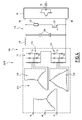
- FIG 4 illustrates a second embodiment of the invention for which elements similar to the first embodiment, described above, are identified by identical references, and are therefore not described again.
- each power supply system 38 and the additional power supply system 40 comprise a frequency converter 100 arranged between the power input 48 and the power output 50, in order to vary the speed of rotation. of the corresponding electric motor 36.
- the frequency converter 100 comprises a voltage transformer 110 connected to the power input 48, a 12-diode diode bridge connected at the output of the voltage transformer, a chopper 114 connected at the output of the twelve-diode diode bridge and the inverter 58. , described above, connected at the output of the chopper 114.
- the twelve-diode diode bridge 112 comprises, as known per se, a first three-phase diode rectifier 116 comprising six diodes 118 and connected to a first set of secondary windings 120 connected in a star form of the voltage transformer, and a second three-phase diode rectifier. 122 having six diodes 118 and connected to a second set of secondary windings 124 connected in a triangle of the voltage transformer.
- the chopper 114 comprises an electromagnetic coil 126 connected to one of the two input terminals 90 of the inverter, two capacitors 128 connected between the two terminals 90, as well as a thyristor 130 and a braking resistor 132 connected in series between the two terminals 90, in parallel capacitors 128.
- the frequency converter 100 of the second embodiment does not make it possible to regenerate active power to the electrical network, nor to supply or absorb reactive energy.
- the frequency converter 100 of the second embodiment unidirectional power, does not allow to feed the ship's electrical network by the terrestrial AC mains.
- the ship according to the invention makes it possible to propose a longitudinal propulsion chain making it possible to facilitate the feeding of the electric motors of the two longitudinal thrusters.
- the invention relates to a ship comprising an electrical network and a propulsion chain connected to the electrical network, the propulsion chain comprising at least a thruster adapted to move the vessel and, for the or each thruster, an electric motor for driving the longitudinal thruster, connected at the input of said thruster, and a power supply system for the electric motor, connected at the input of said engine and connected to the network electric.
- the ship further comprises means for connecting the power system to a terrestrial AC mains, in which the power system is bi-directional in power, and the frequency converter is suitable for converting the supplied current.
- the terrestrial network having a first frequency in a current delivered to the reciprocating network of the ship having a second frequency.
- the electrical network, the thruster, the electric drive motor and the supply system are, for example, identical respectively to the electrical network 12, the longitudinal thruster 34, the electric motor 36 and the system 38 described above with regard to Figures 1 to 3 .
- connection means and the frequency converter are, for example, identical respectively to the connection device 46 and to the frequency converter 52 described above with respect to Figures 1 to 3 .
- the propulsion system comprises, for example, at least one switching device, identical to the auxiliary switching device 44 described above, the auxiliary switching device connecting the power supply system to the electric motor, on the one hand, and the means of connection to the terrestrial electricity network, on the other hand.
- connection device 46 connects the power system 38 to the terrestrial AC mains.
- the power supply system 38 is bi-directional in power, and the frequency converter of said power system then makes it possible to convert the current supplied by the terrestrial network having a first frequency into a current delivered to the AC network of the ship having a second frequency. This then makes it possible to feed the electrical network 12 of the ship without requiring the use of the diesel engines 22.
Landscapes
- Chemical & Material Sciences (AREA)
- Engineering & Computer Science (AREA)
- Combustion & Propulsion (AREA)
- Mechanical Engineering (AREA)
- Ocean & Marine Engineering (AREA)
- Control Of Multiple Motors (AREA)
- Inverter Devices (AREA)
Applications Claiming Priority (1)
| Application Number | Priority Date | Filing Date | Title |
|---|---|---|---|
| FR1058850A FR2966799B1 (fr) | 2010-10-27 | 2010-10-27 | Navire avec un systeme redondant d'alimentation electrique commun au propulseur babord et au propulseur tribord |
Publications (2)
| Publication Number | Publication Date |
|---|---|
| EP2447149A1 true EP2447149A1 (de) | 2012-05-02 |
| EP2447149B1 EP2447149B1 (de) | 2013-12-11 |
Family
ID=44080244
Family Applications (1)
| Application Number | Title | Priority Date | Filing Date |
|---|---|---|---|
| EP11306382.0A Active EP2447149B1 (de) | 2010-10-27 | 2011-10-26 | Schiff mit einem redundanten Stromversorgungssystem, das dem Backbord- und dem Steuerbordantriebssystem gemein ist |
Country Status (3)
| Country | Link |
|---|---|
| EP (1) | EP2447149B1 (de) |
| KR (1) | KR20120047805A (de) |
| FR (1) | FR2966799B1 (de) |
Cited By (1)
| Publication number | Priority date | Publication date | Assignee | Title |
|---|---|---|---|---|
| CN113382923A (zh) * | 2018-12-14 | 2021-09-10 | Abb 有限公司 | 用于摆线船用推进单元的驱动布置、摆线船用推进单元和操作这样的驱动布置的方法 |
Families Citing this family (6)
| Publication number | Priority date | Publication date | Assignee | Title |
|---|---|---|---|---|
| PL3030484T3 (pl) * | 2013-08-06 | 2023-09-18 | Kongsberg Maritime As | Dynamicznie pozycjonowany statek |
| EP2930815B1 (de) | 2014-04-10 | 2018-11-14 | GE Energy Power Conversion Technology Ltd | Stromverteilungssysteme |
| KR101629363B1 (ko) * | 2015-01-07 | 2016-06-10 | 대우조선해양 주식회사 | 폐열회수를 이용한 전력생산 시스템 |
| KR102491160B1 (ko) * | 2016-04-22 | 2023-01-20 | 대우조선해양 주식회사 | 선박의 전기식 추진 시스템 |
| KR102129682B1 (ko) * | 2018-06-18 | 2020-07-02 | 한국조선해양 주식회사 | Ess와 spdt를 이용한 발전기 재투입 시스템을 갖는 선박 |
| KR102115787B1 (ko) * | 2018-09-28 | 2020-06-08 | 현대일렉트릭앤에너지시스템(주) | 직류 선상 전력 시스템 |
Citations (4)
| Publication number | Priority date | Publication date | Assignee | Title |
|---|---|---|---|---|
| DE19522302A1 (de) * | 1995-03-03 | 1996-09-05 | Stn Atlas Elektronik Gmbh | Schiffsantriebsanlage |
| DE19519424A1 (de) * | 1995-05-26 | 1996-11-28 | Stn Atlas Elektronik Gmbh | Stromrichterantrieb |
| GB2442770A (en) * | 2006-10-13 | 2008-04-16 | Rolls Royce Plc | Mixed ship propulsion system |
| WO2008081189A1 (en) * | 2007-01-06 | 2008-07-10 | Converteam Technology Ltd | Power systems |
-
2010
- 2010-10-27 FR FR1058850A patent/FR2966799B1/fr active Active
-
2011
- 2011-10-26 EP EP11306382.0A patent/EP2447149B1/de active Active
- 2011-10-27 KR KR1020110110784A patent/KR20120047805A/ko not_active Withdrawn
Patent Citations (4)
| Publication number | Priority date | Publication date | Assignee | Title |
|---|---|---|---|---|
| DE19522302A1 (de) * | 1995-03-03 | 1996-09-05 | Stn Atlas Elektronik Gmbh | Schiffsantriebsanlage |
| DE19519424A1 (de) * | 1995-05-26 | 1996-11-28 | Stn Atlas Elektronik Gmbh | Stromrichterantrieb |
| GB2442770A (en) * | 2006-10-13 | 2008-04-16 | Rolls Royce Plc | Mixed ship propulsion system |
| WO2008081189A1 (en) * | 2007-01-06 | 2008-07-10 | Converteam Technology Ltd | Power systems |
Cited By (2)
| Publication number | Priority date | Publication date | Assignee | Title |
|---|---|---|---|---|
| CN113382923A (zh) * | 2018-12-14 | 2021-09-10 | Abb 有限公司 | 用于摆线船用推进单元的驱动布置、摆线船用推进单元和操作这样的驱动布置的方法 |
| CN113382923B (zh) * | 2018-12-14 | 2024-04-19 | Abb瑞士股份有限公司 | 驱动布置、摆线船用推进单元和操作驱动布置的方法 |
Also Published As
| Publication number | Publication date |
|---|---|
| FR2966799A1 (fr) | 2012-05-04 |
| FR2966799B1 (fr) | 2012-12-21 |
| KR20120047805A (ko) | 2012-05-14 |
| EP2447149B1 (de) | 2013-12-11 |
Similar Documents
| Publication | Publication Date | Title |
|---|---|---|
| EP2447149B1 (de) | Schiff mit einem redundanten Stromversorgungssystem, das dem Backbord- und dem Steuerbordantriebssystem gemein ist | |
| CA2638224C (fr) | Procede d'alimentation de charges auxiliaires de secours, convertisseur auxiliare et vehicule ferroviaire pour ce procede | |
| KR101628592B1 (ko) | 전기차의 추진 제어 장치 및 그 제어 방법 | |
| CA2604992C (en) | Power distribution systems | |
| US9941772B2 (en) | Marine propulsion systems | |
| CA2743480C (en) | Improved dc bus regulator | |
| EP3208909B1 (de) | System zur verteilung von gemischter elektrischer energie auf gleichstrom und wechselstrom zur stromversorgung von verbrauchern mit variabler frequenz und verbrauchern mit konstanter frequenz | |
| WO2009125012A2 (fr) | Reseau electrique | |
| CA1226653A (fr) | Dispositif d'alimentation d'une charge, notamment un moteur a courant continu pour locomotives ferroviaires du type bi-courant | |
| EP3171505B1 (de) | Ladevorrichtung für eine zugbatterie eines kraftfahrzeugs mit einem zumindest teilweise elektrischen antrieb | |
| KR101878721B1 (ko) | 제로 에미션 운항 하이브리드 전기 선박의 모터 가변 구조 전류 불평형 교정 기능을 갖는 구동 시스템 및 그 제어 방법 | |
| EP2961060A1 (de) | Elektrisches Einspeisesystem einer Ladung, und entsprechendes Einspeiseverfahren | |
| KR101878720B1 (ko) | 제로 에미션 운항 하이브리드 전기 선박의 고효율 가변 구동 전기적 시스템 및 그 제어 방법 | |
| US11833919B2 (en) | Vehicle propulsion system | |
| KR101770129B1 (ko) | 연근해 제로 에미션 존 운항용 하이브리드 전기 선박의 고장 대응을 위한 전기적 시스템 및 그 제어 방법 | |
| FR2998115A1 (fr) | Etage de conversion, convertisseur electrique comportant un tel etage de conversion, dispositif de conversion d'un courant alternatif en un courant continu comportant un tel convertisseur, et borne de rechargement d'une batterie electrique comportant un tel convertisseur ou dispositif de conversion | |
| US20250115364A1 (en) | Power distribution system | |
| EP4701028A1 (de) | Versorgungsnetz für ein flugzeug, entsprechendes luftfahrzeug und steuerungsverfahren | |
| AU2013206813B2 (en) | Improved DC bus regulator |
Legal Events
| Date | Code | Title | Description |
|---|---|---|---|
| PUAI | Public reference made under article 153(3) epc to a published international application that has entered the european phase |
Free format text: ORIGINAL CODE: 0009012 |
|
| AK | Designated contracting states |
Kind code of ref document: A1 Designated state(s): AL AT BE BG CH CY CZ DE DK EE ES FI FR GB GR HR HU IE IS IT LI LT LU LV MC MK MT NL NO PL PT RO RS SE SI SK SM TR |
|
| AX | Request for extension of the european patent |
Extension state: BA ME |
|
| 17P | Request for examination filed |
Effective date: 20121003 |
|
| RIC1 | Information provided on ipc code assigned before grant |
Ipc: B63H 23/24 20060101AFI20130522BHEP Ipc: H02J 4/00 20060101ALI20130522BHEP |
|
| GRAP | Despatch of communication of intention to grant a patent |
Free format text: ORIGINAL CODE: EPIDOSNIGR1 |
|
| INTG | Intention to grant announced |
Effective date: 20130701 |
|
| GRAS | Grant fee paid |
Free format text: ORIGINAL CODE: EPIDOSNIGR3 |
|
| RAP1 | Party data changed (applicant data changed or rights of an application transferred) |
Owner name: GE ENERGY POWER CONVERSION TECHNOLOGY LIMITED |
|
| GRAA | (expected) grant |
Free format text: ORIGINAL CODE: 0009210 |
|
| AK | Designated contracting states |
Kind code of ref document: B1 Designated state(s): AL AT BE BG CH CY CZ DE DK EE ES FI FR GB GR HR HU IE IS IT LI LT LU LV MC MK MT NL NO PL PT RO RS SE SI SK SM TR |
|
| REG | Reference to a national code |
Ref country code: GB Ref legal event code: FG4D Free format text: NOT ENGLISH |
|
| REG | Reference to a national code |
Ref country code: CH Ref legal event code: EP |
|
| REG | Reference to a national code |
Ref country code: AT Ref legal event code: REF Ref document number: 644402 Country of ref document: AT Kind code of ref document: T Effective date: 20140115 |
|
| REG | Reference to a national code |
Ref country code: IE Ref legal event code: FG4D Free format text: LANGUAGE OF EP DOCUMENT: FRENCH |
|
| REG | Reference to a national code |
Ref country code: DE Ref legal event code: R096 Ref document number: 602011004146 Country of ref document: DE Effective date: 20140206 |
|
| REG | Reference to a national code |
Ref country code: NL Ref legal event code: VDEP Effective date: 20131211 |
|
| REG | Reference to a national code |
Ref country code: AT Ref legal event code: MK05 Ref document number: 644402 Country of ref document: AT Kind code of ref document: T Effective date: 20131211 |
|
| PG25 | Lapsed in a contracting state [announced via postgrant information from national office to epo] |
Ref country code: LT Free format text: LAPSE BECAUSE OF FAILURE TO SUBMIT A TRANSLATION OF THE DESCRIPTION OR TO PAY THE FEE WITHIN THE PRESCRIBED TIME-LIMIT Effective date: 20131211 Ref country code: SE Free format text: LAPSE BECAUSE OF FAILURE TO SUBMIT A TRANSLATION OF THE DESCRIPTION OR TO PAY THE FEE WITHIN THE PRESCRIBED TIME-LIMIT Effective date: 20131211 Ref country code: HR Free format text: LAPSE BECAUSE OF FAILURE TO SUBMIT A TRANSLATION OF THE DESCRIPTION OR TO PAY THE FEE WITHIN THE PRESCRIBED TIME-LIMIT Effective date: 20131211 Ref country code: NL Free format text: LAPSE BECAUSE OF FAILURE TO SUBMIT A TRANSLATION OF THE DESCRIPTION OR TO PAY THE FEE WITHIN THE PRESCRIBED TIME-LIMIT Effective date: 20131211 Ref country code: FI Free format text: LAPSE BECAUSE OF FAILURE TO SUBMIT A TRANSLATION OF THE DESCRIPTION OR TO PAY THE FEE WITHIN THE PRESCRIBED TIME-LIMIT Effective date: 20131211 Ref country code: NO Free format text: LAPSE BECAUSE OF FAILURE TO SUBMIT A TRANSLATION OF THE DESCRIPTION OR TO PAY THE FEE WITHIN THE PRESCRIBED TIME-LIMIT Effective date: 20140311 |
|
| REG | Reference to a national code |
Ref country code: LT Ref legal event code: MG4D |
|
| PG25 | Lapsed in a contracting state [announced via postgrant information from national office to epo] |
Ref country code: RS Free format text: LAPSE BECAUSE OF FAILURE TO SUBMIT A TRANSLATION OF THE DESCRIPTION OR TO PAY THE FEE WITHIN THE PRESCRIBED TIME-LIMIT Effective date: 20131211 Ref country code: AT Free format text: LAPSE BECAUSE OF FAILURE TO SUBMIT A TRANSLATION OF THE DESCRIPTION OR TO PAY THE FEE WITHIN THE PRESCRIBED TIME-LIMIT Effective date: 20131211 Ref country code: LV Free format text: LAPSE BECAUSE OF FAILURE TO SUBMIT A TRANSLATION OF THE DESCRIPTION OR TO PAY THE FEE WITHIN THE PRESCRIBED TIME-LIMIT Effective date: 20131211 Ref country code: CY Free format text: LAPSE BECAUSE OF FAILURE TO SUBMIT A TRANSLATION OF THE DESCRIPTION OR TO PAY THE FEE WITHIN THE PRESCRIBED TIME-LIMIT Effective date: 20131211 |
|
| PG25 | Lapsed in a contracting state [announced via postgrant information from national office to epo] |
Ref country code: EE Free format text: LAPSE BECAUSE OF FAILURE TO SUBMIT A TRANSLATION OF THE DESCRIPTION OR TO PAY THE FEE WITHIN THE PRESCRIBED TIME-LIMIT Effective date: 20131211 Ref country code: IS Free format text: LAPSE BECAUSE OF FAILURE TO SUBMIT A TRANSLATION OF THE DESCRIPTION OR TO PAY THE FEE WITHIN THE PRESCRIBED TIME-LIMIT Effective date: 20140411 |
|
| PG25 | Lapsed in a contracting state [announced via postgrant information from national office to epo] |
Ref country code: CZ Free format text: LAPSE BECAUSE OF FAILURE TO SUBMIT A TRANSLATION OF THE DESCRIPTION OR TO PAY THE FEE WITHIN THE PRESCRIBED TIME-LIMIT Effective date: 20131211 Ref country code: SK Free format text: LAPSE BECAUSE OF FAILURE TO SUBMIT A TRANSLATION OF THE DESCRIPTION OR TO PAY THE FEE WITHIN THE PRESCRIBED TIME-LIMIT Effective date: 20131211 Ref country code: RO Free format text: LAPSE BECAUSE OF FAILURE TO SUBMIT A TRANSLATION OF THE DESCRIPTION OR TO PAY THE FEE WITHIN THE PRESCRIBED TIME-LIMIT Effective date: 20131211 Ref country code: PT Free format text: LAPSE BECAUSE OF FAILURE TO SUBMIT A TRANSLATION OF THE DESCRIPTION OR TO PAY THE FEE WITHIN THE PRESCRIBED TIME-LIMIT Effective date: 20140411 Ref country code: ES Free format text: LAPSE BECAUSE OF FAILURE TO SUBMIT A TRANSLATION OF THE DESCRIPTION OR TO PAY THE FEE WITHIN THE PRESCRIBED TIME-LIMIT Effective date: 20131211 Ref country code: PL Free format text: LAPSE BECAUSE OF FAILURE TO SUBMIT A TRANSLATION OF THE DESCRIPTION OR TO PAY THE FEE WITHIN THE PRESCRIBED TIME-LIMIT Effective date: 20131211 |
|
| REG | Reference to a national code |
Ref country code: DE Ref legal event code: R097 Ref document number: 602011004146 Country of ref document: DE |
|
| PLBE | No opposition filed within time limit |
Free format text: ORIGINAL CODE: 0009261 |
|
| STAA | Information on the status of an ep patent application or granted ep patent |
Free format text: STATUS: NO OPPOSITION FILED WITHIN TIME LIMIT |
|
| PG25 | Lapsed in a contracting state [announced via postgrant information from national office to epo] |
Ref country code: DK Free format text: LAPSE BECAUSE OF FAILURE TO SUBMIT A TRANSLATION OF THE DESCRIPTION OR TO PAY THE FEE WITHIN THE PRESCRIBED TIME-LIMIT Effective date: 20131211 |
|
| 26N | No opposition filed |
Effective date: 20140912 |
|
| REG | Reference to a national code |
Ref country code: DE Ref legal event code: R097 Ref document number: 602011004146 Country of ref document: DE Effective date: 20140912 |
|
| PG25 | Lapsed in a contracting state [announced via postgrant information from national office to epo] |
Ref country code: SI Free format text: LAPSE BECAUSE OF FAILURE TO SUBMIT A TRANSLATION OF THE DESCRIPTION OR TO PAY THE FEE WITHIN THE PRESCRIBED TIME-LIMIT Effective date: 20131211 |
|
| PG25 | Lapsed in a contracting state [announced via postgrant information from national office to epo] |
Ref country code: LU Free format text: LAPSE BECAUSE OF FAILURE TO SUBMIT A TRANSLATION OF THE DESCRIPTION OR TO PAY THE FEE WITHIN THE PRESCRIBED TIME-LIMIT Effective date: 20141026 Ref country code: MC Free format text: LAPSE BECAUSE OF FAILURE TO SUBMIT A TRANSLATION OF THE DESCRIPTION OR TO PAY THE FEE WITHIN THE PRESCRIBED TIME-LIMIT Effective date: 20131211 |
|
| REG | Reference to a national code |
Ref country code: CH Ref legal event code: PL |
|
| PG25 | Lapsed in a contracting state [announced via postgrant information from national office to epo] |
Ref country code: BE Free format text: LAPSE BECAUSE OF NON-PAYMENT OF DUE FEES Effective date: 20141031 |
|
| REG | Reference to a national code |
Ref country code: IE Ref legal event code: MM4A |
|
| PG25 | Lapsed in a contracting state [announced via postgrant information from national office to epo] |
Ref country code: LI Free format text: LAPSE BECAUSE OF NON-PAYMENT OF DUE FEES Effective date: 20141031 Ref country code: CH Free format text: LAPSE BECAUSE OF NON-PAYMENT OF DUE FEES Effective date: 20141031 |
|
| REG | Reference to a national code |
Ref country code: FR Ref legal event code: PLFP Year of fee payment: 5 |
|
| PG25 | Lapsed in a contracting state [announced via postgrant information from national office to epo] |
Ref country code: IE Free format text: LAPSE BECAUSE OF NON-PAYMENT OF DUE FEES Effective date: 20141026 |
|
| PG25 | Lapsed in a contracting state [announced via postgrant information from national office to epo] |
Ref country code: SM Free format text: LAPSE BECAUSE OF FAILURE TO SUBMIT A TRANSLATION OF THE DESCRIPTION OR TO PAY THE FEE WITHIN THE PRESCRIBED TIME-LIMIT Effective date: 20131211 |
|
| PG25 | Lapsed in a contracting state [announced via postgrant information from national office to epo] |
Ref country code: GR Free format text: LAPSE BECAUSE OF FAILURE TO SUBMIT A TRANSLATION OF THE DESCRIPTION OR TO PAY THE FEE WITHIN THE PRESCRIBED TIME-LIMIT Effective date: 20140312 Ref country code: IT Free format text: LAPSE BECAUSE OF FAILURE TO SUBMIT A TRANSLATION OF THE DESCRIPTION OR TO PAY THE FEE WITHIN THE PRESCRIBED TIME-LIMIT Effective date: 20131211 Ref country code: BG Free format text: LAPSE BECAUSE OF FAILURE TO SUBMIT A TRANSLATION OF THE DESCRIPTION OR TO PAY THE FEE WITHIN THE PRESCRIBED TIME-LIMIT Effective date: 20131211 |
|
| PG25 | Lapsed in a contracting state [announced via postgrant information from national office to epo] |
Ref country code: TR Free format text: LAPSE BECAUSE OF FAILURE TO SUBMIT A TRANSLATION OF THE DESCRIPTION OR TO PAY THE FEE WITHIN THE PRESCRIBED TIME-LIMIT Effective date: 20131211 Ref country code: HU Free format text: LAPSE BECAUSE OF FAILURE TO SUBMIT A TRANSLATION OF THE DESCRIPTION OR TO PAY THE FEE WITHIN THE PRESCRIBED TIME-LIMIT; INVALID AB INITIO Effective date: 20111026 Ref country code: MT Free format text: LAPSE BECAUSE OF FAILURE TO SUBMIT A TRANSLATION OF THE DESCRIPTION OR TO PAY THE FEE WITHIN THE PRESCRIBED TIME-LIMIT Effective date: 20131211 |
|
| REG | Reference to a national code |
Ref country code: FR Ref legal event code: PLFP Year of fee payment: 6 |
|
| REG | Reference to a national code |
Ref country code: FR Ref legal event code: PLFP Year of fee payment: 7 |
|
| PG25 | Lapsed in a contracting state [announced via postgrant information from national office to epo] |
Ref country code: MK Free format text: LAPSE BECAUSE OF FAILURE TO SUBMIT A TRANSLATION OF THE DESCRIPTION OR TO PAY THE FEE WITHIN THE PRESCRIBED TIME-LIMIT Effective date: 20131211 |
|
| REG | Reference to a national code |
Ref country code: FR Ref legal event code: PLFP Year of fee payment: 8 |
|
| PG25 | Lapsed in a contracting state [announced via postgrant information from national office to epo] |
Ref country code: AL Free format text: LAPSE BECAUSE OF FAILURE TO SUBMIT A TRANSLATION OF THE DESCRIPTION OR TO PAY THE FEE WITHIN THE PRESCRIBED TIME-LIMIT Effective date: 20131211 |
|
| PGFP | Annual fee paid to national office [announced via postgrant information from national office to epo] |
Ref country code: GB Payment date: 20250923 Year of fee payment: 15 |
|
| PGFP | Annual fee paid to national office [announced via postgrant information from national office to epo] |
Ref country code: FR Payment date: 20250924 Year of fee payment: 15 |
|
| PGFP | Annual fee paid to national office [announced via postgrant information from national office to epo] |
Ref country code: DE Payment date: 20250923 Year of fee payment: 15 |