EP2447152A2 - Krügerklappe - Google Patents
Krügerklappe Download PDFInfo
- Publication number
- EP2447152A2 EP2447152A2 EP11184270A EP11184270A EP2447152A2 EP 2447152 A2 EP2447152 A2 EP 2447152A2 EP 11184270 A EP11184270 A EP 11184270A EP 11184270 A EP11184270 A EP 11184270A EP 2447152 A2 EP2447152 A2 EP 2447152A2
- Authority
- EP
- European Patent Office
- Prior art keywords
- krueger
- flow deflector
- trailing edge
- main wing
- deployed
- Prior art date
- Legal status (The legal status is an assumption and is not a legal conclusion. Google has not performed a legal analysis and makes no representation as to the accuracy of the status listed.)
- Granted
Links
- 241000238631 Hexapoda Species 0.000 claims description 6
- 230000000694 effects Effects 0.000 description 7
- 230000007246 mechanism Effects 0.000 description 5
- 230000009286 beneficial effect Effects 0.000 description 3
- 230000008901 benefit Effects 0.000 description 3
- 230000007423 decrease Effects 0.000 description 3
- 238000009434 installation Methods 0.000 description 3
- 230000002250 progressing effect Effects 0.000 description 3
- 230000002411 adverse Effects 0.000 description 2
- 230000006872 improvement Effects 0.000 description 2
- 230000003134 recirculating effect Effects 0.000 description 2
- 230000009471 action Effects 0.000 description 1
- 230000015556 catabolic process Effects 0.000 description 1
- 230000003247 decreasing effect Effects 0.000 description 1
- 238000006731 degradation reaction Methods 0.000 description 1
- 230000003993 interaction Effects 0.000 description 1
- 238000012423 maintenance Methods 0.000 description 1
- 238000004519 manufacturing process Methods 0.000 description 1
- 238000012986 modification Methods 0.000 description 1
- 230000004048 modification Effects 0.000 description 1
- 230000008092 positive effect Effects 0.000 description 1
- 230000000750 progressive effect Effects 0.000 description 1
- 230000009467 reduction Effects 0.000 description 1
- 230000008439 repair process Effects 0.000 description 1
- 238000000926 separation method Methods 0.000 description 1
- 238000011144 upstream manufacturing Methods 0.000 description 1
Images

Classifications
-
- B—PERFORMING OPERATIONS; TRANSPORTING
- B64—AIRCRAFT; AVIATION; COSMONAUTICS
- B64C—AEROPLANES; HELICOPTERS
- B64C9/00—Adjustable control surfaces or members, e.g. rudders
- B64C9/14—Adjustable control surfaces or members, e.g. rudders forming slots
- B64C9/22—Adjustable control surfaces or members, e.g. rudders forming slots at the front of the wing
- B64C9/24—Adjustable control surfaces or members, e.g. rudders forming slots at the front of the wing by single flap
-
- B—PERFORMING OPERATIONS; TRANSPORTING
- B64—AIRCRAFT; AVIATION; COSMONAUTICS
- B64C—AEROPLANES; HELICOPTERS
- B64C9/00—Adjustable control surfaces or members, e.g. rudders
- B64C9/14—Adjustable control surfaces or members, e.g. rudders forming slots
- B64C2009/143—Adjustable control surfaces or members, e.g. rudders forming slots comprising independently adjustable elements for closing or opening the slot between the main wing and leading or trailing edge flaps
-
- Y—GENERAL TAGGING OF NEW TECHNOLOGICAL DEVELOPMENTS; GENERAL TAGGING OF CROSS-SECTIONAL TECHNOLOGIES SPANNING OVER SEVERAL SECTIONS OF THE IPC; TECHNICAL SUBJECTS COVERED BY FORMER USPC CROSS-REFERENCE ART COLLECTIONS [XRACs] AND DIGESTS
- Y02—TECHNOLOGIES OR APPLICATIONS FOR MITIGATION OR ADAPTATION AGAINST CLIMATE CHANGE
- Y02T—CLIMATE CHANGE MITIGATION TECHNOLOGIES RELATED TO TRANSPORTATION
- Y02T50/00—Aeronautics or air transport
- Y02T50/40—Weight reduction
Definitions
- the present invention relates to a Krueger, or leading edge flap, for an aircraft wing.
- a Krueger, or leading edge flap is a high-lift device deployable from the lower aerodynamic surface of an aerofoil, such as an aircraft wing.
- an aerofoil such as an aircraft wing.
- the Krueger trailing edge When stowed the Krueger trailing edge is disposed at or near the wing leading edge, and a portion of the Krueger device makes up part of the wing lower surface.
- the Krueger rotates forwardly from a hinge near the wing leading edge, and the Krueger trailing edge remains adjacent the wing leading edge.
- Krueger Whilst the Krueger is functionally similar to a slat when deployed, slats are deployed forwardly from the wing leading edge.
- Leading edge high-lift devices can be either "slotted” or "un-slotted".
- Slotted means that a gap, or slot, is opened up between the deployed high-lift device and the wing leading edge.
- Un-slotted means that the deployed high-lift device is sealed to the wing leading edge. Airflow through the slotted gap can improve the maximum lift coefficient of the wing in a high-lift configuration, i.e. with the high-lift device deployed.
- the gap between the deployed high-lift device and the wing should be convergent. That is to say, the gap between the wing leading edge and the lower aerodynamic surface of the high-lift device should progressively reduce up to the trailing edge of the deployed high-lift device. If the slot is convergent-divergent the circulation around the high-lift device is reduced due to the less than optimal aerodynamic setting.
- a convergent slot can normally be achieved by positioning the deployed device at an appropriate angle and location ahead of the wing leading edge.
- kinematic constraints particularly for Krueger actuation mechanisms, can limit the positioning of the deployed device and create a convergent-divergent slot.
- the available extent of rotation of the Krueger during deployment will affect the angle of the deployed Krueger. Further rotation to an aerodynamically more desirable angle may not be possible without resulting in a more complex, heavier design.
- a first aspect of the invention provides a Krueger, or leading edge flap, deployable from a lower aerodynamic surface of an aircraft main wing element so as to form a slot between the Krueger and the main wing element when deployed, the deployed Krueger having a leading edge, a trailing edge and upper and lower aerodynamic surfaces extending between the leading edge and the trailing edge, and a flow deflector which provides an effectively divergent flap profile thickness in the downstream direction at or adjacent the Krueger trailing edge so as to direct airflow away from the lower aerodynamic surface of the deployed Krueger towards an upper aerodynamic surface of the main wing element.
- a further aspect of the invention provides an aircraft wing assembly including a main wing element and a Krueger in accordance with the first aspect.
- the invention is advantageous in that the flow deflector acts to reduce, or eliminate, slot divergence, particularly where this cannot otherwise be achieved due to kinematic constraints.
- the profile of the upper aerodynamic surface of the Krueger is dictated by the profile of the lower surface of the main wing element, since these must match when the Krueger is retracted. By directing the airflow away from adjacent the trailing edge of the lower aerodynamic surface of the Krueger towards the wing upper surface the flow deflector can reduce, or eliminate the slot divergence.
- the flow deflector may be fixed with respect to the Krueger trailing edge.
- the entire Krueger including the flow deflector is stowed within a profile of the main wing element when the Krueger is retracted. Therefore, the fixed flow deflector does not contribute to cruise drag.
- the lower surface panel of the main wing element from which the Krueger is constructed can be flexible or rigid depending on the design concept of the Krueger.
- the Krueger trailing edge may be flexible.
- the flow deflector may be formed as a profiled surface of the Krueger lower aerodynamic surface.
- the upper and lower Krueger aerodynamic surfaces may be divergent in the downstream direction at or adjacent the Krueger trailing edge.
- the flow deflector may be formed as a profiled component, e.g. a wedge, attached to the Krueger lower aerodynamic surface at or adjacent the Krueger trailing edge.
- the flow deflector may be detachable from the Krueger lower surface.
- the flow deflector effectively forms a divergent Krueger profile in the Krueger trailing edge region such that airflow over the lower aerodynamic surface is deflected downwardly towards the upper surface of the main wing element. It is not necessary that the divergent Krueger profile has its thickest part exactly at the Krueger trailing edge.
- the flow deflector may provide a profile thickness for the Krueger adjacent the Krueger trailing edge that is greater than the Krueger profile thickness forward of the flow deflector.
- the flow deflector may be formed as a tab projecting downwardly from the Krueger lower aerodynamic surface at or adjacent the Krueger trailing edge.
- the tab creates a region or recirculating air just in front of the tab which has the effect of smoothly deflecting the bulk airflow over the lower aerodynamic surface of the Krueger downwardly towards the upper surface of the main wing element.
- the flow deflector at or adjacent the Krueger trailing edge is not limited to a consistent thickness or angle across the span of the Krueger.
- the thickness may vary progressively across the span or may alternatively be applied in a stepped variation to form a castellated or sawtooth pattern.
- a stepped variation can act as vortex generators by introducing multiple vortical flows into the slot across the Krueger span. This can improve mixing between the wake from the Krueger trailing edge and the flow through the slot which can reduce the adverse interference between the wake and the wing boundary layer. There is therefore a resultant improvement in the maximum lift of the wing.
- Krueger/flow deflector design therefore needs to be optimised for maximum aerodynamic performance.
- Integrally forming the flow deflector with the Krueger may provide advantages in terms of reduced maintenance, reduced parts count, reduced production time, improved stiffness and weight saving.
- a detachable flow deflector may provide advantages for ease of removal for repair, testing etc.
- the deployed Krueger may act as an insect shield for the main wing element. This would be particularly beneficial where the wing is a "laminar wing", i.e. where the intention is to maintain a laminar boundary layer over a large percentage of the wing at cruise. Insect debris on the wing leading edge can promote turbulent boundary layer flow.
- the invention is also applicable to conventional, non-laminar, wings.
- the slot which opens up between the Krueger and the main wing element when the Krueger is deployed, is preferably convergent forward of the flow deflector in the direction of the onset flow.
- the flow deflector reduces, or eliminates, divergence of the slot adjacent the Krueger trailing edge.
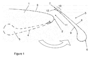
- Figure 1 illustrates an aircraft wing comprising a main ("fixed") wing element 1 having a leading edge 2, an upper aerodynamic surface 3, and a lower aerodynamic surface 4.
- the upper and lower aerodynamic surfaces 3, 4 meet at the leading edge 2.
- a Krueger 5 is mounted to the main wing element 1 for movement between a retracted position (shown in broken line) and a deployed position (shown in full line).
- the leading edge Krueger 5 is a high-lift device deployed at low speed and high incidence to increase the camber and maximum lift coefficient of the wing.
- the Krueger is movable between its deployed and retracted positions by a Krueger actuation mechanism, which has been omitted from Figure 1 for clarity.
- the deployed Krueger 5 has a leading edge 6, a trailing edge 7, an upper aerodynamic surface 8 and a lower aerodynamic surface 9.
- the upper and lower aerodynamic surfaces 8, 9 meet at the leading and trailing edges 6, 7.
- a region of the Krueger adjacent the trailing edge 7 will hereafter be referred to as the trailing edge region 10.
- the retracted Krueger 5 is stowed within the profile of the main wing element 1.
- the Krueger surface 8 forms part of the lower aerodynamic surface 4 of the main wing element 1 when the Krueger is retracted. Accordingly, the Krueger surface 8 is profiled to match the lower aerodynamic surface 4 of the main wing element 1.
- the Krueger 5 rotates forwardly from the lower aerodynamic surface 4 of the main wing element 1 under action of the Krueger actuation mechanism (not shown) pivotally connected at one or more points to the Krueger 5.
- the deployed Krueger 5 forms a slot 11 between the main wing element 1 and the Krueger lower aerodynamic surface 9.
- the Krueger 5 is therefore known as a "slotted Krueger". Airflow through the slot 11 acts to increase circulation around the Krueger which suppresses the leading edge suction pressure peak of the main wing, so improving aerodynamic performance of the wing at high incidence by delaying flow separation.
- the Krueger 5 has a flow deflector 12 on the lower aerodynamic surface 9 in the trailing edge region 10. Without the flow deflector, the gap between the main wing element 1 and the lower aerodynamic surface 9 of the Krueger 5 would be decreasing and then increasing when progressing around from the wing leading edge 2 towards the Krueger trailing edge 7. This decreasing-increasing gap forms a convergent-divergent slot.
- the slot is only convergent such that it maximises the circulation around the Krueger to suppress the leading edge suction peak on the main wing element and provide a high maximum lift coefficient on the wing.
- the slot is convergent-divergent, then the airflow through the slot provides a reduced circulation around the Krueger with the subsequent degradation of the maximum lift coefficient of the wing as a result of an increase of the wing leading edge pressure suction peak.
- the slot 11 geometry is defined, in part, by the angle and location of the deployed Krueger 5 ahead of the wing leading edge 2.
- Kinematic constraints on the Krueger actuation mechanism mean that the slot geometry cannot be optimised as this would result in a more complex, heavier Krueger actuation mechanism design. Instead, the flow deflector 12 acts to reduce, or eliminate the slot divergence.
- the flow diverter 12 is stowed with the Krueger 5 within the profile of the main wing element 1 when the Krueger is retracted. Therefore, the flow deflector 12 does not contribute to cruise drag.
- the flow deflector 12 comprises a small, curved wedge attached to the lower aerodynamic Krueger surface 9 positioned at the trailing edge region 10.
- the flow deflector 12 directs the airflow away from the lower Krueger surface 9 towards the wing upper surface 3 which has the effect of converging the flow in the slot 11 between the wing leading edge 2 and the Krueger trailing edge 7. This can have an aerodynamic benefit of providing an improved circulation of the flow around the Krueger which reduces the wing suction peak pressures and subsequently improves the wing boundary layer.
- the wedge-shaped flow deflector 12 necessarily increases the thickness of the Krueger trailing edge 7. This thick trailing edge creates a thicker wake from the Krueger 5, which undesirably could interfere with the wing boundary layer.
- the design of the of the flow deflector 12 can be optimised to maximise the desirable effects of increased Krueger circulation and minimise the undesirable effects of the thicker Krueger wake.
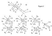
- the wedge-shaped flow deflector 12 is shown in detail in Figure 2a ) and features a tapered front edge 13 blended into the lower aerodynamic Krueger surface 9, and a blunt planar back face 14 coincident with the Krueger trailing edge 7.
- the flow deflector 12 has a concave lower surface 15.
- the minimum profile thickness d 1 for the Krueger 5 occurs just forward (upstream) of the Krueger trailing edge region 10.
- the maximum profile thickness d 2 in the Krueger trailing edge region 10 dictates the Krueger wake thickness. In this embodiment, d 2 is coincident with the Krueger trailing edge 7.
- the flow deflector 12 is a separate part attached to the lower aerodynamic Krueger surface 9, the flow deflector could be integrally formed with the Krueger 5. In this case, the lower aerodynamic Krueger surface 9 would be profiled to form the flow deflector 12.
- Figures 2b) to 2h ) illustrate several alternative arrangements for the flow deflector.
- the flow deflector 112 has a wedge-shaped profile and features a tapered front edge 113 blended into the lower aerodynamic Krueger surface 9, and a blunt planar back face 114 extending rearwardly from the Krueger trailing edge 7.
- the flow deflector 112 has a concave lower surface 115.
- the maximum profile thickness d 12 is aft of the Krueger trailing edge 7.
- the flow deflector 212 has a triangular profile and features a planar inclined front face 213 and a planar inclined back face 214 extending to the Krueger trailing edge 7.
- the maximum profile thickness d 22 is forward of the Krueger trailing edge 7.
- the flow deflector 312 features a convex lower surface 315 and a blunt planar back face 314 substantially coincident with the Krueger trailing edge 7.
- the maximum profile thickness d 32 is coincident with the Krueger trailing edge 7.
- the flow deflector 412 features a concave front surface 413, which is blended into the lower aerodynamic Krueger surface 9, and a concave back surface 414, which extends to the Krueger trailing edge 7.
- the maximum profile thickness d 42 is forward of the Krueger trailing edge 7.
- the flow deflector 512 has a triangular profile and features a planar inclined lower surface 515 and a planar inclined back face 514 extending rearwardly from the Krueger trailing edge 7.
- the maximum profile thickness d 52 is aft of the Krueger trailing edge 7.
- the flow deflector 612 has a convex lower surface 615 extending from the lower aerodynamic Krueger surface 9 to the Krueger trailing edge 7.
- the maximum profile thickness d 62 is forward of the Krueger trailing edge 7.
- the flow deflectors 112, 212, 312, 412, 512, and 612 may be formed as separate parts attached to the lower aerodynamic Krueger surface, or may be integrally formed with the Krueger 5.
- the flow deflector 712 is formed as a tab 713 extending downwardly from the lower aerodynamic Krueger surface 9 adjacent the Krueger trailing edge 7.
- the tab 713 creates a region or recirculating air just in front of the tab such that the bulk airflow over the lower aerodynamic Krueger surface 9 is deflected downwardly
- This type of deflector could be fixed or hinged about its base.
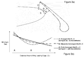
- Figure 3a illustrates graphically the convergence criteria of a gap between the main wing element and the deployed Krueger.
- Figure 3b illustrates the graphical plot showing three cases where the gap is measured along a distance S from the leading edge of the main wing to the Krueger lower surface up to its trailing edge.
- a Krueger with a trailing edge flow deflector in accordance with the invention forms a marginally convergent slot, where the trailing edge flow deflector reduces the distance from the Krueger lower surface to the wing leading edge such that it reaches a minimum at the Krueger trailing edge trailing edge C.
- a Krueger with a trailing edge flow deflector in accordance with the invention forms a fully convergent slot, where the distance from the Krueger trailing edge to the wing leading edge C is further reduced to provide a progressive reduction of the gap towards the Krueger trailing edge.
- Case (1) illustrates the sub-optimal condition in which kinematic constraints on the Krueger (without the flow deflector) create a slot gap which decreases and then increases when progressing aft from the leading edge of the main wing element to the Krueger trailing edge. This therefore forms a convergent-divergent slot.
- Case (2) with the flow deflector applied, has a slot gap which decreases when progressing aft from the leading edge of the main wing element towards the Krueger trailing edge to provide a marginally convergent slot.
- This gap could also increase slightly at the Krueger trailing edge but the flow deflector still acts to significantly reduce the slot divergence to provide a beneficial aerodynamic effect.
- the deployed Krueger in accordance with the invention will in most cases have its trailing edge in a higher position relative to the main wing element than would normally be the case. This is due to the under rotation of the Krueger to its deployed position owing to the kinematic constraints. However, this high trailing edge position can have a desirable effect since the Krueger may act as an insect shield for the main wing element. This may be particularly beneficial where the wing is a "laminar wing". Insect debris on the main wing element leading edge can promote turbulent flow and so insect shielding helps maintain laminar flow.
- Figures 4a) to 4h) illustrate examples of three dimensional installations of the flow deflector.
- Figure 4a illustrates a flow deflector having a regular sawtooth shape across the span.
- Figure 4b illustrates a flow deflector having a varying sawtooth shape across the span.
- Figure 4c illustrates a flow deflector having a regular castellation shape across the span.
- Figure 4d illustrates a flow deflector having a varying castellation shape across the span.
- Figure 4e illustrates a flow deflector having a continuous wedge shape across the span.
- Figure 4f illustrates a flow deflector having a continuous wedge shape with one or more intermittent breaks across the span.
- Figure 4g illustrates a flow deflector having a smoothly varying continuous wedge shape across the span.
- Figures 4a) to 4g illustrate examples of three dimensional installations of the flow deflector having either: constant or varying thickness across the Krueger span; castellated or sawtooth shape variation across the Krueger span; discontinuous application across the Krueger span; or any combination of the above.
- the three dimensional variation in the shape of the flow deflector can be adapted to provide a distribution of vortex generators for introducing multiple vortical flows into the slot across the Krueger span. This can improve mixing between the wake from the Krueger trailing edge and the flow through the slot which can reduce the adverse interference between the wake and the wing boundary layer. There is therefore a resultant improvement in the maximum lift of the wing.
Landscapes
- Engineering & Computer Science (AREA)
- Aviation & Aerospace Engineering (AREA)
- Aiming, Guidance, Guns With A Light Source, Armor, Camouflage, And Targets (AREA)
- Structures Of Non-Positive Displacement Pumps (AREA)
Applications Claiming Priority (1)
| Application Number | Priority Date | Filing Date | Title |
|---|---|---|---|
| GBGB1018176.6A GB201018176D0 (en) | 2010-10-28 | 2010-10-28 | Krueger |
Publications (3)
| Publication Number | Publication Date |
|---|---|
| EP2447152A2 true EP2447152A2 (de) | 2012-05-02 |
| EP2447152A3 EP2447152A3 (de) | 2016-03-16 |
| EP2447152B1 EP2447152B1 (de) | 2017-09-06 |
Family
ID=43365627
Family Applications (1)
| Application Number | Title | Priority Date | Filing Date |
|---|---|---|---|
| EP11184270.4A Not-in-force EP2447152B1 (de) | 2010-10-28 | 2011-10-07 | Krügerklappe |
Country Status (3)
| Country | Link |
|---|---|
| US (1) | US8657239B2 (de) |
| EP (1) | EP2447152B1 (de) |
| GB (1) | GB201018176D0 (de) |
Families Citing this family (3)
| Publication number | Priority date | Publication date | Assignee | Title |
|---|---|---|---|---|
| DE102010014792A1 (de) * | 2010-04-13 | 2011-10-13 | Airbus Operations Gmbh | Hochauftriebssystem für ein Flugzeug |
| DE102011018906A1 (de) * | 2011-04-28 | 2012-10-31 | Airbus Operations Gmbh | Hochauftriebssystem für ein Flugzeug und Verfahren zum Beeinflussen der Hochauftriebseigenschaften eines Flugzeugs |
| US20170152018A1 (en) * | 2015-12-01 | 2017-06-01 | The Boeing Company | Leading edge high-lift device |
Family Cites Families (28)
| Publication number | Priority date | Publication date | Assignee | Title |
|---|---|---|---|---|
| US3578264A (en) * | 1968-07-09 | 1971-05-11 | Battelle Development Corp | Boundary layer control of flow separation and heat exchange |
| US4354648A (en) * | 1980-02-06 | 1982-10-19 | Gates Learjet Corporation | Airstream modification device for airfoils |
| US5058837A (en) * | 1989-04-07 | 1991-10-22 | Wheeler Gary O | Low drag vortex generators |
| GB2260521B (en) | 1991-10-19 | 1995-03-22 | British Aerospace | An aircraft wing leading edge arrangement |
| US5158252A (en) | 1991-10-24 | 1992-10-27 | The Boeing Company | Three-position variable camber Krueger leading edge flap |
| US5598990A (en) * | 1994-12-15 | 1997-02-04 | University Of Kansas Center For Research Inc. | Supersonic vortex generator |
| CA2168003C (en) * | 1996-02-02 | 2001-04-17 | Carl W. Millard | Large aircraft critical surface covers |
| US6598834B2 (en) * | 2000-02-14 | 2003-07-29 | Aerotech Services Inc. | Method for reducing fuel consumption in aircraft |
| DE10019185C2 (de) * | 2000-04-17 | 2003-06-05 | Airbus Gmbh | Anordnung zur aerodynamischen Lärmminderung von Vorflügeln eines Verkehrsflugzeuges |
| US6435458B1 (en) * | 2001-02-12 | 2002-08-20 | The Boeing Company | Tailored wing assembly for an aircraft moveable slat system |
| EP1338506A1 (de) * | 2002-02-15 | 2003-08-27 | Fairchild Dornier GmbH | Flugzeugflügel mit Spalt- und Krüger-Klappen |
| US7270305B2 (en) * | 2004-06-15 | 2007-09-18 | The Boeing Company | Aircraft leading edge apparatuses and corresponding methods |
| DE102004049504A1 (de) * | 2004-10-11 | 2006-04-13 | Airbus Deutschland Gmbh | Flugzeugflügel, Verfahren zum Betreiben eines Flugzeugflügels und Verwendung einer schwenkbaren Hinterkante an einem Hauptflügel eines Flugzeugflügels zum Justieren der Form und Breite eines Luftspalts |
| DE102004056537B4 (de) * | 2004-11-23 | 2010-09-09 | Eads Deutschland Gmbh | Anordnung zur Minderung des aerodynamischen Lärms an einem Zusatzflügel eines Flugzeuges |
| US7322547B2 (en) * | 2005-01-31 | 2008-01-29 | The Boeing Company | Aerospace vehicle leading edge slat devices and corresponding methods |
| US7578484B2 (en) * | 2006-06-14 | 2009-08-25 | The Boeing Company | Link mechanisms for gapped rigid krueger flaps, and associated systems and methods |
| DE102006053259A1 (de) * | 2006-11-11 | 2008-05-21 | Airbus Deutschland Gmbh | Hochauftriebssystem am Tragflügel eines Flugzeugs und Verfahren zu seiner Betätigung |
| DE102007061590A1 (de) * | 2007-12-20 | 2009-08-13 | Airbus Deutschland Gmbh | Hochauftriebssystem für ein Flugzeug mit einem Hauptflügel und einem verstellbaren Vorflügel |
| DE102008033005A1 (de) * | 2008-07-14 | 2010-03-18 | Airbus Deutschland Gmbh | Aerodynamische Klappe und Flügel |
| ITTO20080566A1 (it) * | 2008-07-23 | 2010-01-24 | Alenia Aeronautica Spa | Dispositivo attuatore basato su lega a memoria di forma e gruppo di flap alare dotato di un tale dispositivo attuatore |
| US8226048B2 (en) * | 2008-12-09 | 2012-07-24 | The Boeing Company | Link mechanisms, including Stephenson II link mechanisms for multi-position flaps and associated systems and methods |
| GB0908354D0 (en) * | 2009-05-15 | 2009-06-24 | Airbus Uk Ltd | Blade seal |
| GB0908751D0 (en) * | 2009-05-21 | 2009-07-01 | Airbus Uk Ltd | Slot seal |
| GB0911012D0 (en) * | 2009-06-25 | 2009-08-12 | Airbus Operations Ltd | Cross-bleed dam |
| US8210482B2 (en) * | 2009-10-27 | 2012-07-03 | Lockheed Martin Corporation | Prismatic-shaped vortex generators |
| DE102009057340A1 (de) * | 2009-12-07 | 2011-06-09 | Airbus Operations Gmbh | Hochauftriebssystem für ein Flugzeug, Verfahren zum Bewegen einer Auftriebsklappe und Flugzeug mit einem Hochauftriebssystem |
| DE102010026619B4 (de) * | 2010-07-09 | 2018-11-15 | Airbus Operations Gmbh | Vorflügel mit flexibler Hinterkante |
| US8573541B2 (en) * | 2010-09-13 | 2013-11-05 | John Sullivan | Wavy airfoil |
-
2010
- 2010-10-28 GB GBGB1018176.6A patent/GB201018176D0/en not_active Ceased
-
2011
- 2011-10-07 EP EP11184270.4A patent/EP2447152B1/de not_active Not-in-force
- 2011-10-24 US US13/279,642 patent/US8657239B2/en not_active Expired - Fee Related
Non-Patent Citations (1)
| Title |
|---|
| None |
Also Published As
| Publication number | Publication date |
|---|---|
| GB201018176D0 (en) | 2010-12-08 |
| US8657239B2 (en) | 2014-02-25 |
| US20120104180A1 (en) | 2012-05-03 |
| EP2447152A3 (de) | 2016-03-16 |
| EP2447152B1 (de) | 2017-09-06 |
Similar Documents
| Publication | Publication Date | Title |
|---|---|---|
| US7900868B2 (en) | Noise-shielding wing configuration | |
| US8596586B2 (en) | High-lift system for an aircraft, method for displacing a lift flap, and aircraft having a high-lift system | |
| US4702441A (en) | Aircraft wing stall control device and method | |
| US8231084B2 (en) | Aircraft wing | |
| EP3184417B1 (de) | Hochauftriebsvorrichtung für flugzeuge | |
| US20110114795A1 (en) | Aerodynamic Flap and Wing | |
| CN102844237B (zh) | 用于飞机的高升力系统以及飞机 | |
| CA2719163C (en) | Improved slat configuration for fixed-wing aircraft | |
| EP2447152B1 (de) | Krügerklappe | |
| US9440729B2 (en) | High-lift-device, wing, and noise reduction device for high-lift-device | |
| US20090108142A1 (en) | Aircraft wing with slotted high lift system | |
| EP3647183B1 (de) | Aerodynamische struktur für flugzeugflügel | |
| US20120187253A1 (en) | Leading edge device for an aircraft | |
| US20110044812A1 (en) | Airfoil with flow deflector | |
| US20240246657A1 (en) | Leading-edge high-lift device, wing, and aircraft | |
| CN219008104U (zh) | 飞机后缘襟翼 | |
| Murayama et al. | Computational Study on Track Noise From Infinite Wing with Leading-Edge Krueger Flap | |
| CN121553360A (zh) | 襟翼涡流干扰装置及包括该襟翼涡流干扰装置的机翼组件 | |
| CN118953666A (zh) | 一种流动控制的机翼前缘结构及机翼 | |
| WO2022249758A1 (ja) | 前縁高揚力装置、翼および航空機、ならびに緩衝部材 | |
| CN117775272A (zh) | 飞机的前缘缝翼及机翼 | |
| JP2000264290A (ja) | フラップ |
Legal Events
| Date | Code | Title | Description |
|---|---|---|---|
| PUAI | Public reference made under article 153(3) epc to a published international application that has entered the european phase |
Free format text: ORIGINAL CODE: 0009012 |
|
| AK | Designated contracting states |
Kind code of ref document: A2 Designated state(s): AL AT BE BG CH CY CZ DE DK EE ES FI FR GB GR HR HU IE IS IT LI LT LU LV MC MK MT NL NO PL PT RO RS SE SI SK SM TR |
|
| AX | Request for extension of the european patent |
Extension state: BA ME |
|
| PUAL | Search report despatched |
Free format text: ORIGINAL CODE: 0009013 |
|
| AK | Designated contracting states |
Kind code of ref document: A3 Designated state(s): AL AT BE BG CH CY CZ DE DK EE ES FI FR GB GR HR HU IE IS IT LI LT LU LV MC MK MT NL NO PL PT RO RS SE SI SK SM TR |
|
| AX | Request for extension of the european patent |
Extension state: BA ME |
|
| RIC1 | Information provided on ipc code assigned before grant |
Ipc: B64C 9/14 20060101ALN20160208BHEP Ipc: B64C 9/24 20060101AFI20160208BHEP |
|
| 17P | Request for examination filed |
Effective date: 20160916 |
|
| RBV | Designated contracting states (corrected) |
Designated state(s): AL AT BE BG CH CY CZ DE DK EE ES FI FR GB GR HR HU IE IS IT LI LT LU LV MC MK MT NL NO PL PT RO RS SE SI SK SM TR |
|
| GRAP | Despatch of communication of intention to grant a patent |
Free format text: ORIGINAL CODE: EPIDOSNIGR1 |
|
| GRAJ | Information related to disapproval of communication of intention to grant by the applicant or resumption of examination proceedings by the epo deleted |
Free format text: ORIGINAL CODE: EPIDOSDIGR1 |
|
| RIC1 | Information provided on ipc code assigned before grant |
Ipc: B64C 9/14 20060101ALN20161007BHEP Ipc: B64C 9/24 20060101AFI20161007BHEP |
|
| INTG | Intention to grant announced |
Effective date: 20161031 |
|
| INTC | Intention to grant announced (deleted) | ||
| 17Q | First examination report despatched |
Effective date: 20161128 |
|
| RIC1 | Information provided on ipc code assigned before grant |
Ipc: B64C 9/14 20060101ALN20170201BHEP Ipc: B64C 9/24 20060101AFI20170201BHEP |
|
| GRAP | Despatch of communication of intention to grant a patent |
Free format text: ORIGINAL CODE: EPIDOSNIGR1 |
|
| INTG | Intention to grant announced |
Effective date: 20170406 |
|
| GRAS | Grant fee paid |
Free format text: ORIGINAL CODE: EPIDOSNIGR3 |
|
| GRAA | (expected) grant |
Free format text: ORIGINAL CODE: 0009210 |
|
| AK | Designated contracting states |
Kind code of ref document: B1 Designated state(s): AL AT BE BG CH CY CZ DE DK EE ES FI FR GB GR HR HU IE IS IT LI LT LU LV MC MK MT NL NO PL PT RO RS SE SI SK SM TR |
|
| REG | Reference to a national code |
Ref country code: GB Ref legal event code: FG4D |
|
| REG | Reference to a national code |
Ref country code: CH Ref legal event code: EP Ref country code: AT Ref legal event code: REF Ref document number: 925577 Country of ref document: AT Kind code of ref document: T Effective date: 20170915 |
|
| REG | Reference to a national code |
Ref country code: IE Ref legal event code: FG4D |
|
| REG | Reference to a national code |
Ref country code: DE Ref legal event code: R096 Ref document number: 602011041244 Country of ref document: DE |
|
| REG | Reference to a national code |
Ref country code: FR Ref legal event code: PLFP Year of fee payment: 7 |
|
| REG | Reference to a national code |
Ref country code: NL Ref legal event code: MP Effective date: 20170906 |
|
| REG | Reference to a national code |
Ref country code: LT Ref legal event code: MG4D |
|
| PG25 | Lapsed in a contracting state [announced via postgrant information from national office to epo] |
Ref country code: SE Free format text: LAPSE BECAUSE OF FAILURE TO SUBMIT A TRANSLATION OF THE DESCRIPTION OR TO PAY THE FEE WITHIN THE PRESCRIBED TIME-LIMIT Effective date: 20170906 Ref country code: HR Free format text: LAPSE BECAUSE OF FAILURE TO SUBMIT A TRANSLATION OF THE DESCRIPTION OR TO PAY THE FEE WITHIN THE PRESCRIBED TIME-LIMIT Effective date: 20170906 Ref country code: LT Free format text: LAPSE BECAUSE OF FAILURE TO SUBMIT A TRANSLATION OF THE DESCRIPTION OR TO PAY THE FEE WITHIN THE PRESCRIBED TIME-LIMIT Effective date: 20170906 Ref country code: FI Free format text: LAPSE BECAUSE OF FAILURE TO SUBMIT A TRANSLATION OF THE DESCRIPTION OR TO PAY THE FEE WITHIN THE PRESCRIBED TIME-LIMIT Effective date: 20170906 Ref country code: NO Free format text: LAPSE BECAUSE OF FAILURE TO SUBMIT A TRANSLATION OF THE DESCRIPTION OR TO PAY THE FEE WITHIN THE PRESCRIBED TIME-LIMIT Effective date: 20171206 |
|
| REG | Reference to a national code |
Ref country code: AT Ref legal event code: MK05 Ref document number: 925577 Country of ref document: AT Kind code of ref document: T Effective date: 20170906 |
|
| PG25 | Lapsed in a contracting state [announced via postgrant information from national office to epo] |
Ref country code: BG Free format text: LAPSE BECAUSE OF FAILURE TO SUBMIT A TRANSLATION OF THE DESCRIPTION OR TO PAY THE FEE WITHIN THE PRESCRIBED TIME-LIMIT Effective date: 20171206 Ref country code: ES Free format text: LAPSE BECAUSE OF FAILURE TO SUBMIT A TRANSLATION OF THE DESCRIPTION OR TO PAY THE FEE WITHIN THE PRESCRIBED TIME-LIMIT Effective date: 20170906 Ref country code: GR Free format text: LAPSE BECAUSE OF FAILURE TO SUBMIT A TRANSLATION OF THE DESCRIPTION OR TO PAY THE FEE WITHIN THE PRESCRIBED TIME-LIMIT Effective date: 20171207 Ref country code: RS Free format text: LAPSE BECAUSE OF FAILURE TO SUBMIT A TRANSLATION OF THE DESCRIPTION OR TO PAY THE FEE WITHIN THE PRESCRIBED TIME-LIMIT Effective date: 20170906 Ref country code: LV Free format text: LAPSE BECAUSE OF FAILURE TO SUBMIT A TRANSLATION OF THE DESCRIPTION OR TO PAY THE FEE WITHIN THE PRESCRIBED TIME-LIMIT Effective date: 20170906 |
|
| PG25 | Lapsed in a contracting state [announced via postgrant information from national office to epo] |
Ref country code: NL Free format text: LAPSE BECAUSE OF FAILURE TO SUBMIT A TRANSLATION OF THE DESCRIPTION OR TO PAY THE FEE WITHIN THE PRESCRIBED TIME-LIMIT Effective date: 20170906 |
|
| PG25 | Lapsed in a contracting state [announced via postgrant information from national office to epo] |
Ref country code: PL Free format text: LAPSE BECAUSE OF FAILURE TO SUBMIT A TRANSLATION OF THE DESCRIPTION OR TO PAY THE FEE WITHIN THE PRESCRIBED TIME-LIMIT Effective date: 20170906 Ref country code: RO Free format text: LAPSE BECAUSE OF FAILURE TO SUBMIT A TRANSLATION OF THE DESCRIPTION OR TO PAY THE FEE WITHIN THE PRESCRIBED TIME-LIMIT Effective date: 20170906 Ref country code: CZ Free format text: LAPSE BECAUSE OF FAILURE TO SUBMIT A TRANSLATION OF THE DESCRIPTION OR TO PAY THE FEE WITHIN THE PRESCRIBED TIME-LIMIT Effective date: 20170906 |
|
| PG25 | Lapsed in a contracting state [announced via postgrant information from national office to epo] |
Ref country code: IS Free format text: LAPSE BECAUSE OF FAILURE TO SUBMIT A TRANSLATION OF THE DESCRIPTION OR TO PAY THE FEE WITHIN THE PRESCRIBED TIME-LIMIT Effective date: 20180106 Ref country code: AT Free format text: LAPSE BECAUSE OF FAILURE TO SUBMIT A TRANSLATION OF THE DESCRIPTION OR TO PAY THE FEE WITHIN THE PRESCRIBED TIME-LIMIT Effective date: 20170906 Ref country code: SM Free format text: LAPSE BECAUSE OF FAILURE TO SUBMIT A TRANSLATION OF THE DESCRIPTION OR TO PAY THE FEE WITHIN THE PRESCRIBED TIME-LIMIT Effective date: 20170906 Ref country code: SK Free format text: LAPSE BECAUSE OF FAILURE TO SUBMIT A TRANSLATION OF THE DESCRIPTION OR TO PAY THE FEE WITHIN THE PRESCRIBED TIME-LIMIT Effective date: 20170906 Ref country code: IT Free format text: LAPSE BECAUSE OF FAILURE TO SUBMIT A TRANSLATION OF THE DESCRIPTION OR TO PAY THE FEE WITHIN THE PRESCRIBED TIME-LIMIT Effective date: 20170906 Ref country code: EE Free format text: LAPSE BECAUSE OF FAILURE TO SUBMIT A TRANSLATION OF THE DESCRIPTION OR TO PAY THE FEE WITHIN THE PRESCRIBED TIME-LIMIT Effective date: 20170906 |
|
| REG | Reference to a national code |
Ref country code: CH Ref legal event code: PL |
|
| REG | Reference to a national code |
Ref country code: DE Ref legal event code: R097 Ref document number: 602011041244 Country of ref document: DE |
|
| PG25 | Lapsed in a contracting state [announced via postgrant information from national office to epo] |
Ref country code: MC Free format text: LAPSE BECAUSE OF FAILURE TO SUBMIT A TRANSLATION OF THE DESCRIPTION OR TO PAY THE FEE WITHIN THE PRESCRIBED TIME-LIMIT Effective date: 20170906 |
|
| PLBE | No opposition filed within time limit |
Free format text: ORIGINAL CODE: 0009261 |
|
| STAA | Information on the status of an ep patent application or granted ep patent |
Free format text: STATUS: NO OPPOSITION FILED WITHIN TIME LIMIT |
|
| REG | Reference to a national code |
Ref country code: IE Ref legal event code: MM4A |
|
| PG25 | Lapsed in a contracting state [announced via postgrant information from national office to epo] |
Ref country code: LI Free format text: LAPSE BECAUSE OF NON-PAYMENT OF DUE FEES Effective date: 20171031 Ref country code: DK Free format text: LAPSE BECAUSE OF FAILURE TO SUBMIT A TRANSLATION OF THE DESCRIPTION OR TO PAY THE FEE WITHIN THE PRESCRIBED TIME-LIMIT Effective date: 20170906 Ref country code: LU Free format text: LAPSE BECAUSE OF NON-PAYMENT OF DUE FEES Effective date: 20171007 Ref country code: CH Free format text: LAPSE BECAUSE OF NON-PAYMENT OF DUE FEES Effective date: 20171031 |
|
| 26N | No opposition filed |
Effective date: 20180607 |
|
| REG | Reference to a national code |
Ref country code: BE Ref legal event code: MM Effective date: 20171031 |
|
| PG25 | Lapsed in a contracting state [announced via postgrant information from national office to epo] |
Ref country code: BE Free format text: LAPSE BECAUSE OF NON-PAYMENT OF DUE FEES Effective date: 20171031 Ref country code: SI Free format text: LAPSE BECAUSE OF FAILURE TO SUBMIT A TRANSLATION OF THE DESCRIPTION OR TO PAY THE FEE WITHIN THE PRESCRIBED TIME-LIMIT Effective date: 20170906 |
|
| PG25 | Lapsed in a contracting state [announced via postgrant information from national office to epo] |
Ref country code: MT Free format text: LAPSE BECAUSE OF NON-PAYMENT OF DUE FEES Effective date: 20171007 |
|
| REG | Reference to a national code |
Ref country code: FR Ref legal event code: PLFP Year of fee payment: 8 |
|
| PG25 | Lapsed in a contracting state [announced via postgrant information from national office to epo] |
Ref country code: IE Free format text: LAPSE BECAUSE OF NON-PAYMENT OF DUE FEES Effective date: 20171007 |
|
| PG25 | Lapsed in a contracting state [announced via postgrant information from national office to epo] |
Ref country code: HU Free format text: LAPSE BECAUSE OF FAILURE TO SUBMIT A TRANSLATION OF THE DESCRIPTION OR TO PAY THE FEE WITHIN THE PRESCRIBED TIME-LIMIT; INVALID AB INITIO Effective date: 20111007 |
|
| PG25 | Lapsed in a contracting state [announced via postgrant information from national office to epo] |
Ref country code: CY Free format text: LAPSE BECAUSE OF NON-PAYMENT OF DUE FEES Effective date: 20170906 |
|
| PG25 | Lapsed in a contracting state [announced via postgrant information from national office to epo] |
Ref country code: MK Free format text: LAPSE BECAUSE OF FAILURE TO SUBMIT A TRANSLATION OF THE DESCRIPTION OR TO PAY THE FEE WITHIN THE PRESCRIBED TIME-LIMIT Effective date: 20170906 |
|
| PG25 | Lapsed in a contracting state [announced via postgrant information from national office to epo] |
Ref country code: TR Free format text: LAPSE BECAUSE OF FAILURE TO SUBMIT A TRANSLATION OF THE DESCRIPTION OR TO PAY THE FEE WITHIN THE PRESCRIBED TIME-LIMIT Effective date: 20170906 |
|
| PG25 | Lapsed in a contracting state [announced via postgrant information from national office to epo] |
Ref country code: PT Free format text: LAPSE BECAUSE OF FAILURE TO SUBMIT A TRANSLATION OF THE DESCRIPTION OR TO PAY THE FEE WITHIN THE PRESCRIBED TIME-LIMIT Effective date: 20170906 |
|
| PG25 | Lapsed in a contracting state [announced via postgrant information from national office to epo] |
Ref country code: AL Free format text: LAPSE BECAUSE OF FAILURE TO SUBMIT A TRANSLATION OF THE DESCRIPTION OR TO PAY THE FEE WITHIN THE PRESCRIBED TIME-LIMIT Effective date: 20170906 |
|
| PGFP | Annual fee paid to national office [announced via postgrant information from national office to epo] |
Ref country code: GB Payment date: 20211022 Year of fee payment: 11 Ref country code: DE Payment date: 20211020 Year of fee payment: 11 |
|
| PGFP | Annual fee paid to national office [announced via postgrant information from national office to epo] |
Ref country code: FR Payment date: 20211022 Year of fee payment: 11 |
|
| REG | Reference to a national code |
Ref country code: DE Ref legal event code: R119 Ref document number: 602011041244 Country of ref document: DE |
|
| GBPC | Gb: european patent ceased through non-payment of renewal fee |
Effective date: 20221007 |
|
| PG25 | Lapsed in a contracting state [announced via postgrant information from national office to epo] |
Ref country code: FR Free format text: LAPSE BECAUSE OF NON-PAYMENT OF DUE FEES Effective date: 20221031 Ref country code: DE Free format text: LAPSE BECAUSE OF NON-PAYMENT OF DUE FEES Effective date: 20230503 |
|
| PG25 | Lapsed in a contracting state [announced via postgrant information from national office to epo] |
Ref country code: GB Free format text: LAPSE BECAUSE OF NON-PAYMENT OF DUE FEES Effective date: 20221007 |