EP2447157B1 - Boîtier de ventilateur et ensemble d'encliquetage de bague de montage - Google Patents
Boîtier de ventilateur et ensemble d'encliquetage de bague de montage Download PDFInfo
- Publication number
- EP2447157B1 EP2447157B1 EP11186657.0A EP11186657A EP2447157B1 EP 2447157 B1 EP2447157 B1 EP 2447157B1 EP 11186657 A EP11186657 A EP 11186657A EP 2447157 B1 EP2447157 B1 EP 2447157B1
- Authority
- EP
- European Patent Office
- Prior art keywords
- mount ring
- case
- fan
- cylindrical case
- mount
- Prior art date
- Legal status (The legal status is an assumption and is not a legal conclusion. Google has not performed a legal analysis and makes no representation as to the accuracy of the status listed.)
- Active
Links
Images

Classifications
-
- F—MECHANICAL ENGINEERING; LIGHTING; HEATING; WEAPONS; BLASTING
- F01—MACHINES OR ENGINES IN GENERAL; ENGINE PLANTS IN GENERAL; STEAM ENGINES
- F01D—NON-POSITIVE DISPLACEMENT MACHINES OR ENGINES, e.g. STEAM TURBINES
- F01D21/00—Shutting-down of machines or engines, e.g. in emergency; Regulating, controlling, or safety means not otherwise provided for
- F01D21/04—Shutting-down of machines or engines, e.g. in emergency; Regulating, controlling, or safety means not otherwise provided for responsive to undesired position of rotor relative to stator or to breaking-off of a part of the rotor, e.g. indicating such position
- F01D21/045—Shutting-down of machines or engines, e.g. in emergency; Regulating, controlling, or safety means not otherwise provided for responsive to undesired position of rotor relative to stator or to breaking-off of a part of the rotor, e.g. indicating such position special arrangements in stators or in rotors dealing with breaking-off of part of rotor
-
- B—PERFORMING OPERATIONS; TRANSPORTING
- B64—AIRCRAFT; AVIATION; COSMONAUTICS
- B64D—EQUIPMENT FOR FITTING IN OR TO AIRCRAFT; FLIGHT SUITS; PARACHUTES; ARRANGEMENT OR MOUNTING OF POWER PLANTS OR PROPULSION TRANSMISSIONS IN AIRCRAFT
- B64D27/00—Arrangement or mounting of power plants in aircraft; Aircraft characterised by the type or position of power plants
- B64D27/40—Arrangements for mounting power plants in aircraft
- B64D27/402—Arrangements for mounting power plants in aircraft comprising box like supporting frames, e.g. pylons or arrangements for embracing the power plant
-
- F—MECHANICAL ENGINEERING; LIGHTING; HEATING; WEAPONS; BLASTING
- F02—COMBUSTION ENGINES; HOT-GAS OR COMBUSTION-PRODUCT ENGINE PLANTS
- F02C—GAS-TURBINE PLANTS; AIR INTAKES FOR JET-PROPULSION PLANTS; CONTROLLING FUEL SUPPLY IN AIR-BREATHING JET-PROPULSION PLANTS
- F02C7/00—Features, components parts, details or accessories, not provided for in, or of interest apart form groups F02C1/00 - F02C6/00; Air intakes for jet-propulsion plants
- F02C7/04—Air intakes for gas-turbine plants or jet-propulsion plants
-
- F—MECHANICAL ENGINEERING; LIGHTING; HEATING; WEAPONS; BLASTING
- F05—INDEXING SCHEMES RELATING TO ENGINES OR PUMPS IN VARIOUS SUBCLASSES OF CLASSES F01-F04
- F05D—INDEXING SCHEME FOR ASPECTS RELATING TO NON-POSITIVE-DISPLACEMENT MACHINES OR ENGINES, GAS-TURBINES OR JET-PROPULSION PLANTS
- F05D2300/00—Materials; Properties thereof
- F05D2300/60—Properties or characteristics given to material by treatment or manufacturing
- F05D2300/603—Composites; e.g. fibre-reinforced
-
- Y—GENERAL TAGGING OF NEW TECHNOLOGICAL DEVELOPMENTS; GENERAL TAGGING OF CROSS-SECTIONAL TECHNOLOGIES SPANNING OVER SEVERAL SECTIONS OF THE IPC; TECHNICAL SUBJECTS COVERED BY FORMER USPC CROSS-REFERENCE ART COLLECTIONS [XRACs] AND DIGESTS
- Y02—TECHNOLOGIES OR APPLICATIONS FOR MITIGATION OR ADAPTATION AGAINST CLIMATE CHANGE
- Y02T—CLIMATE CHANGE MITIGATION TECHNOLOGIES RELATED TO TRANSPORTATION
- Y02T50/00—Aeronautics or air transport
- Y02T50/40—Weight reduction
-
- Y—GENERAL TAGGING OF NEW TECHNOLOGICAL DEVELOPMENTS; GENERAL TAGGING OF CROSS-SECTIONAL TECHNOLOGIES SPANNING OVER SEVERAL SECTIONS OF THE IPC; TECHNICAL SUBJECTS COVERED BY FORMER USPC CROSS-REFERENCE ART COLLECTIONS [XRACs] AND DIGESTS
- Y02—TECHNOLOGIES OR APPLICATIONS FOR MITIGATION OR ADAPTATION AGAINST CLIMATE CHANGE
- Y02T—CLIMATE CHANGE MITIGATION TECHNOLOGIES RELATED TO TRANSPORTATION
- Y02T50/00—Aeronautics or air transport
- Y02T50/60—Efficient propulsion technologies, e.g. for aircraft
-
- Y—GENERAL TAGGING OF NEW TECHNOLOGICAL DEVELOPMENTS; GENERAL TAGGING OF CROSS-SECTIONAL TECHNOLOGIES SPANNING OVER SEVERAL SECTIONS OF THE IPC; TECHNICAL SUBJECTS COVERED BY FORMER USPC CROSS-REFERENCE ART COLLECTIONS [XRACs] AND DIGESTS
- Y10—TECHNICAL SUBJECTS COVERED BY FORMER USPC
- Y10T—TECHNICAL SUBJECTS COVERED BY FORMER US CLASSIFICATION
- Y10T29/00—Metal working
- Y10T29/49—Method of mechanical manufacture
- Y10T29/49229—Prime mover or fluid pump making
Definitions
- This disclosure pertains to a composite fan containment case for a gas turbine engine. Specifically, this disclosure relates to a composite fan containment case including a mount ring that at least partially supports the containment case and the gas turbine engine.
- a gas turbine engine can include a fan section containing fan blades surrounded by a fan case supported within a nacelle.
- the function of the fan case is to contain fractured and separated parts of the fan blades, preventing any portions from leaving the fan nacelle.
- Metallic fan cases can be undesirably heavy to perform this containment function.
- a composite fan case constructed of non-metallic materials can reduce weight and provide the same containment capability as a metallic fan.
- Document US8021102 shows a composite fan containment case and methods of fabrication the same.
- a fan component case as set forth in claim 1.
- An example disclosed fan containment case includes a mount ring that supports a portion of the engine core.
- the example mount ring includes lugs and other features that define mounting locations for the gas turbine engine.
- the example fan containment case includes a generally cylindrically shaped fan case that extends between an open front end and an open rear end.
- the mount ring is secured onto an outer surface of the fan case.
- the mount ring includes one or more mounting flanges and a plurality of openings for attachment of gas turbine engine components.
- the example mount ring is attached to the containment case utilizing an interference fit. Once the mount ring is secured onto the outer case, fasteners extending through openings within the mount ring attach the fan case to guide vanes of the gas turbine engine.
- the combination of the interference fit along with the plurality of fasteners that extend through both the mount ring and the fan case provide adequate structure to support the engine.
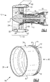
- a gas turbine engine is schematically indicated at 10 and includes a core 12 having a compressor section 14, a combustion section 16 and a turbine section 18.
- the example gas turbine engine 10 includes a fan section 20 that is disposed within a nacelle 22 and includes a plurality of blades 28.
- the compressor, combustion, turbine, and fan sections 14, 16, 18 and 20 are arranged about an axis 15.
- the nacelle 22 defines an inlet 24 for incoming airflow.
- a fan containment case 26 is disposed proximate to the blades 28 within the fan section 20.
- the example containment case includes a mount ring 32 attached to a mount beam 54 attached to a frame member such as a pylon 60 of an aircraft.
- the mount ring 32 is also attached to at least one guide vane section 56 that extends from the engine core 12 to the containment case 26.
- the example containment case 26 includes the mount ring 32 that supports a portion of the engine core 12.
- the guide vanes 56 that are disposed rearward of the fan section 20 are static relative to the rotating blades 28 and provide one of several mounting locations that support the engine core 12.
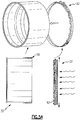
- the example fan containment case assembly 26 includes a generally cylindrically shaped fan case 30 that extends between an open front end 38 and an open rear end 40.
- the mount ring 32 is secured onto an outer surface 34 of the aft end of the fan case 30 and overlaps a portion of the outer surface 34 of the composite containment case 30.
- the mount ring 32 includes one or more mounting flanges 42.
- the example mounting flange 42 extends radially outward from the mount ring 32 to provide a connection to the forward primary engine mount beam 54.
- the example mounting flange 42 includes a fail safe lug 45 that extends upward between primary lugs 43.
- the mounting flange 42 corresponds to a configuration of the engine mount beam 54 for securing the engine core 12 to the pylon 60 of the aircraft.
- other mounting flange configurations could be utilized with contemplation of this disclosure.
- the example fan case 30 is comprised of a plurality of composite layers 58.
- the plurality of composite layers 58 forms the generally cylindrical geometry of the case 30.
- the mount ring 32 fits over the outer surface 34 of the fan case 30 and is a forged ring of metal material.
- the disclosed example mount ring 32 is formed from titanium and fabricated through a forming process followed by secondary machining to form the various details and features of the disclosed mount ring 32.
- the example mount ring 32 includes a lead in chamfer 50 that aids in guiding the mount ring 32 over the fan case 30 during assembly.
- the fan case 30 includes a sacrificial material 36 that is disposed along an axial length of the outer surface of the mount ring 32 that is at least as long as the mount ring 32. The sacrificial material 36 is machined prior to installation of the mount ring 32 to provide the desired interference fit between the mount ring 32 and the outer surface 34 of the fan case 30.
- the mount ring 32 also includes an axial locating feature for installation.
- the example axial locating feature is a tab 46 that extends radially inward to abut the back end 40.
- the mount ring 32 is slid onto the fan case 30 to abut the tab 46. Abutment of the tab 46 against the back end 40 provides the desired location of the mount ring 32 onto the fan case 30.
- the axial locator 46 provides that the mount ring 32 is fit as desired to the containment case 30.
- the tab 46 is fit all about the circumference of the back end 40 that provides axial alignment between the mount ring 32 and the case 30.
- the tab 46 can be continuous about the circumference of the back end 40 or may be segmented. Moreover the tab 46 may vary in size and shape depending on axial locating requirements of the mount ring 32.
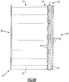
- the mount ring 32 includes one or more mounting flanges 42 that extend radially upward and outward.
- One of two primary lugs 43 is shown in Figure 4 and includes openings 44 that receive bushings 52.
- the bushings 52 are aligned to receive a fastener when secured to the engine mount beam 54.
- the mount ring 32 also includes rearward extending portion with a radial groove 48 that is provided to engage components that interface with the containment case 30.
- the groove 48 provides a fit for a non-fastener attachment element that fits within the groove 48.
- the example mount ring 32 is fit to the containment case 30 utilizing an interference fit.
- the interference fit is defined by the inner diameter of the mount ring 32 and the outer diameter of the fan case 30.
- the mount ring 32 is fit over the sacrificial material 36 that is layered on the outer surface 34 of the fan case 30.
- the sacrificial material 36 is machined to provide a final outer diameter dimension that corresponds with the inner diameter of the mount ring 32.
- fasteners 65 extend through openings 62 within the mount ring 32 and openings 64 in the fan case 30 to attach the mount ring 32 and the fan case to the fan exit guide vanes 56 ( Figure 1 ) within the fan section 20.
- the combination of the interference fit along with the plurality of fasteners that extend through both the mount ring 32 and the fan case 30 secure the mount ring 32 in place on the case 30.
- the mount ring 32 is secured to the engine core 12 by way of the guide vanes 56.
- the interference fit between the mount ring 32 and fan case 30 or additional fasteners maintain the relative position of the mount ring 32 and the fan case 30 until installation and mounting of the gas turbine engine 10 are complete.
- the example fan containment case 26 is fabricated by fitting the mount ring 32 onto the outer surface 34 of the fan case 30.
- the fan case 30 is formed from a plurality of composite materials to form the generally cylindrical case.
- An outer surface of the fan case 30 is covered with the sacrificial material 36.
- the example sacrificial material 36 is a plurality of fiberglass sheets that are machined to provide a desired surface finish.
- the thickness of the sacrificial material 36 is provided to define and correspond with a desired outer diameter of the fan case 30 that corresponds with the desired inner diameter of the mount ring 32 and the resulting interference fit.
- the mount ring 32 is formed from a titanium material and is installed on to the fan case by heating to expand such that it will fit over the outer diameter of the fan case 30 and specifically onto the surface defined by the sacrificial material 36. Heating of the mount ring 32 expands it radially outward to increase the size of the inner diameter to allow the mount ring 32 to fit over the fan case 30. Once the mount ring 32 is inserted onto the fan case 30 it is allowed to cool and contract. After cooling and the resulting contraction of the mount ring 32, an interference fit is formed that provides load transfer from the mount ring 32 to the fan case 30.
- the method steps for fabricating the example containment case 26 include forming the case 30 from a plurality of composite materials to form a generally cylindrical case having a front end 38 and a back end 40.
- the sacrificial material 36 is applied to the outer surface 34 at a thickness that provides sufficient desired machining allowances such that a desired outer diameter can be formed.
- the desired outer diameter of the sacrificial material 36 corresponds to a desired interference fit with the mount ring 32.
- the example sacrificial material 36 is fiberglass and can be applied according to known methods.
- other machinable materials could be layered and applied to provide a machinable surface desired for the example sacrificial material 36.
- the sacrificial material 36 can be co-cured with the carbon material and layers utilized for defining the fan case 30 or added in a later processing step.
- the example sacrificial material 36 is then machined using known methods to grind, cut or otherwise remove material to obtain the desired outer diameter adjacent the back end of the fan case 30.
- the method continues by forming the mount ring 32 from a titanium material.
- the forming step can be any step as is known in the art including forging, molding or other steps utilized and known to form shaped components from metal materials.
- a titanium material is disclosed by way of example, other metal materials, metal composites and alloys are also within the contemplation of this disclosure.
- the specific features of the mount ring 32 are formed by secondary machining processes. These features include but are not limited to the tab 46 and the lead in chamber 50. Moreover, the example mount ring 32 includes openings provided for fasteners for the mounting of the guide vanes. Further, shaping and machining may be performed to define a desired inner diameter along with a rings, grooves, tabs or other features as may be desired to improve stability and strength.
- the mount ring 32 is heated to a temperature that expands the mount ring 32 such that an inner diameter of the mount ring 32 grows to be capable of sliding over and onto the sacrificial material 36 at the back end 40 of the composite case 30.
- the example mount ring 32 is provided with the lead in chamfer 50 to aid installation and provide an initial fit over the back side 40 of the containment case 30. Once the lead in 50 is over the end of the fan case 40 the remainder of the mount ring 32 is pressed onto the back end 40 of the fan case 30 until the tab 46 engages the back end 40.
- the mount ring 32 is allowed to cool. Cooling of the mount ring 32 contracts the mount ring 32 around the case 30 to form an interference fit with the fan case 30 such that the mount ring 32 becomes a substantially integral part of the fan case 30.
- openings 64 are formed through the mount ring 32 and into the fan case 30 using known machining techniques.
- the mount ring 32 includes a plurality of defined openings 62 that are formed prior to attachment to the fan case 30.
- the fan case 30 is not provided with any openings so that alignment of openings is not a factor during the mounting process of the mount ring 32. This eliminates the need for circumferential alignment of the fan case 30 with the mount ring 32 during attachment of the mount ring 32.
- the openings 62 defined in the mount ring 32 are utilized to subsequently form corresponding openings 64 ( Figure 4 ) through the fan case 30.
- the openings 62, 64 that are utilized for attaching the mount ring 32 to the various guide vanes 56 of the engine core 12 are formed once the mount ring 32 is mounted to the fan case 30 there is no need to provide a clocking feature to circumferentially align the mount ring 32 onto the fan case 30. It is within the contemplation of this disclosure that an alignment feature such as a pin and slot could be utilized to set a desired relative circumferential position between the mount ring 32 and the fan case 30.
- the example containment case provides for the formation of a fan containment case 26 with an integral mount ring 32 that provides the connection between the engine core 12 and the engine mount 54.
Landscapes
- Engineering & Computer Science (AREA)
- Chemical & Material Sciences (AREA)
- Combustion & Propulsion (AREA)
- Mechanical Engineering (AREA)
- General Engineering & Computer Science (AREA)
- Aviation & Aerospace Engineering (AREA)
- Structures Of Non-Positive Displacement Pumps (AREA)
- Turbine Rotor Nozzle Sealing (AREA)
Claims (11)
- Boîtier de confinement de ventilateur (26) comprenant :une pluralité de couches composites (58) définissant un boîtier généralement cylindrique (30) comportant une surface externe (34) et une extrémité arrière (40) ; et caractérisé parune bague de montage (32) fixée à la surface externe (34) du boîtier cylindrique au niveau de l'extrémité arrière (40), la bague de montage (32) étant constituée d'un métal.
- Boîtier de confinement de ventilateur selon la revendication 1, dans lequel la bague de montage (32) comporte un élément de positionnement axial (46) venant en butée contre l'extrémité arrière du boîtier cylindrique (30).
- Boîtier de confinement de ventilateur selon la revendication 1 ou 2, dans lequel la bague de montage (32) comporte un chanfrein d'entrée (50) pour guider la bague de montage (32) sur l'extrémité arrière (40) du boîtier cylindrique (30).
- Boîtier de confinement de ventilateur selon une quelconque revendication précédente, dans lequel la bague de montage (32) comporte une ou plusieurs pattes s'étendant radialement (43) pour fixer le boîtier de confinement de ventilateur (30) à un support de moteur.
- Boîtier de confinement de ventilateur selon une quelconque revendication précédente, dans lequel la bague de montage (32) comporte une pluralité d'ouvertures s'étendant radialement (62) pour fixer le boîtier généralement cylindrique (30) à une aube directrice (56).
- Boîtier de confinement de ventilateur selon une quelconque revendication précédente, dans lequel la bague de montage (32) comprend un diamètre interne qui s'ajuste sur la surface externe (34) du boîtier cylindrique (30) dans un ajustement serré.
- Boîtier de confinement de ventilateur selon une quelconque revendication précédente, dans lequel la surface externe (34) du boîtier cylindrique (30) comporte un matériau usinable (36) sur lequel la bague de montage (32) est fixée.
- Boîtier de confinement de ventilateur selon une quelconque revendication précédente, dans lequel la bague de montage (32) comporte une rainure externe en forme de V (48), destinée à être couplée à des structures supplémentaires du boîtier de confinement de ventilateur.
- Procédé de fabrication d'un boîtier de confinement de ventilateur comprenant :la formation d'un boîtier généralement cylindrique (30) avec une pluralité de couches composites (58) ;la formation d'une bague de montage (32) à partir d'un matériau en métal ;l'extension de la bague de montage (32) par chauffage ;le coulissement de la bague de montage (32) sur une extrémité arrière (40) du boîtier cylindrique (30) ; etla rétraction de la bague de montage (32) par refroidissement pour former un ajustement serré entre une surface interne de la bague de montage (32) et une surface externe (34) du boîtier cylindrique (30).
- Procédé selon la revendication 9, comportant une ou plusieurs des étapes suivantes :la fourniture d'un matériau sacrificiel (36) sur une surface externe (34) du boîtier cylindrique (30) et l'usinage du matériau sacrificiel (36) en fonction d'un diamètre interne de la bague de montage (32) pour définir l'ajustement serré ;la formation de la bague de montage (32) pour inclure un élément de positionnement axial (46) et l'élément de positionnement axial venant en butée (46) contre l'extrémité arrière (40) du boîtier cylindrique (30) lors du coulissement de la bague de montage (32) sur le boîtier cylindrique (30) ;la formation d'une patte s'étendant radialement (43) sur la bague de montage (32) ; etla formation d'une rainure externe en forme de V (38) sur la bague de montage (32).
- Procédé selon la revendication 9 ou 10, comportant la formation d'ouvertures (62, 64) à travers la bague de montage (32) et le boîtier cylindrique (30) pour des éléments de fixation (65).
Applications Claiming Priority (1)
| Application Number | Priority Date | Filing Date | Title |
|---|---|---|---|
| US12/912,189 US9114882B2 (en) | 2010-10-26 | 2010-10-26 | Fan case and mount ring snap fit assembly |
Publications (3)
| Publication Number | Publication Date |
|---|---|
| EP2447157A2 EP2447157A2 (fr) | 2012-05-02 |
| EP2447157A3 EP2447157A3 (fr) | 2015-04-08 |
| EP2447157B1 true EP2447157B1 (fr) | 2019-09-04 |
Family
ID=44992575
Family Applications (1)
| Application Number | Title | Priority Date | Filing Date |
|---|---|---|---|
| EP11186657.0A Active EP2447157B1 (fr) | 2010-10-26 | 2011-10-26 | Boîtier de ventilateur et ensemble d'encliquetage de bague de montage |
Country Status (2)
| Country | Link |
|---|---|
| US (1) | US9114882B2 (fr) |
| EP (1) | EP2447157B1 (fr) |
Families Citing this family (27)
| Publication number | Priority date | Publication date | Assignee | Title |
|---|---|---|---|---|
| US9140138B2 (en) * | 2012-05-31 | 2015-09-22 | Hamilton Sundstrand Corporation | Turbomachine containment structure |
| US9151181B2 (en) * | 2012-06-19 | 2015-10-06 | United Technologies Corporation | Metallic rails on composite fan case |
| US20140003923A1 (en) | 2012-07-02 | 2014-01-02 | Peter Finnigan | Functionally graded composite fan containment case |
| US9482111B2 (en) | 2012-12-14 | 2016-11-01 | United Technologies Corporation | Fan containment case with thermally conforming liner |
| FR2999651B1 (fr) * | 2012-12-18 | 2015-01-16 | Snecma | Extension de carter intermediaire a conception amelioree |
| US20150377073A1 (en) * | 2013-03-15 | 2015-12-31 | United Technologies Corporation | Titanium aluminide turbine exhaust structure |
| GB201306674D0 (en) * | 2013-04-12 | 2013-05-29 | Rolls Royce Plc | Rigid Raft for a Gas Turbine Engine |
| FR3008912B1 (fr) * | 2013-07-29 | 2017-12-15 | Snecma | Carter de turbomachine et procede de fabrication |
| US10221718B2 (en) | 2013-09-09 | 2019-03-05 | United Technologies Corporation | Fan cases and manufacture methods |
| JP6118721B2 (ja) * | 2013-12-20 | 2017-04-19 | 株式会社Ihi | ファンケース及びファンケースの製造方法 |
| DE102014208923B4 (de) | 2014-05-12 | 2017-10-19 | Technische Universität Dresden | Verfahren zur Verbindung eines Triebwerk-Gehäuseelements aus Faserverbundmaterial mit einem metallischen Anschlusselement |
| DE102014208921B4 (de) | 2014-05-12 | 2017-10-19 | Technische Universität Dresden | Triebwerkaußenstruktur aus Faserverbundwerkstoff mit integralem metallischen Anschlusselement |
| WO2016027368A1 (fr) * | 2014-08-22 | 2016-02-25 | 株式会社Ihi | Boîtier cylindrique |
| US10107202B2 (en) * | 2014-11-26 | 2018-10-23 | United Technologies Corporation | Composite fan housing assembly of a turbofan engine and method of manufacture |
| US10202866B2 (en) * | 2014-12-04 | 2019-02-12 | United Technologies Corporation | Ground handling system for a composite fan case and a method of using the same |
| EP3106289B1 (fr) | 2015-06-17 | 2023-10-18 | Raytheon Technologies Corporation | Anneau de confinement de boîtier de ventilateur métallique co-moulé |
| US10082042B2 (en) * | 2015-06-22 | 2018-09-25 | United Technologies Corporation | Case coupling and assembly |
| US10883385B2 (en) | 2016-08-29 | 2021-01-05 | Raytheon Technologies Corporation | Thermal barrier washer |
| US10697325B2 (en) | 2016-08-29 | 2020-06-30 | Raytheon Technologies Corporation | Thermal barrier seal |
| US20180221958A1 (en) * | 2017-02-07 | 2018-08-09 | General Electric Company | Parts and methods for producing parts using hybrid additive manufacturing techniques |
| US10677260B2 (en) | 2017-02-21 | 2020-06-09 | General Electric Company | Turbine engine and method of manufacturing |
| US10550718B2 (en) * | 2017-03-31 | 2020-02-04 | The Boeing Company | Gas turbine engine fan blade containment systems |
| US10487684B2 (en) | 2017-03-31 | 2019-11-26 | The Boeing Company | Gas turbine engine fan blade containment systems |
| US11077954B2 (en) | 2017-12-20 | 2021-08-03 | General Electric Company | Connection assembly for mounting engine and engine mounting system comprising the same |
| GB2575296B (en) * | 2018-07-04 | 2022-06-29 | Rolls Royce Plc | Method and tooling for manufacturing a fan case assembly |
| US11162425B2 (en) | 2019-06-11 | 2021-11-02 | Rolls-Royce Corporation | Assembly fixture |
| CN115182816A (zh) * | 2021-04-01 | 2022-10-14 | 中国航发商用航空发动机有限责任公司 | 机匣、机匣的制备方法及航空发动机 |
Family Cites Families (12)
| Publication number | Priority date | Publication date | Assignee | Title |
|---|---|---|---|---|
| GB2044358B (en) * | 1979-03-10 | 1983-01-19 | Rolls Royce | Gas turbine jet engine mounting |
| FR2610673B1 (fr) | 1987-02-05 | 1991-03-15 | Snecma | Turboreacteur multiflux a couronne externe de redresseur de soufflante frettee sur le carter |
| GB9922618D0 (en) | 1999-09-25 | 1999-11-24 | Rolls Royce Plc | A gas turbine engine blade containment assembly |
| DE10259943A1 (de) | 2002-12-20 | 2004-07-01 | Rolls-Royce Deutschland Ltd & Co Kg | Schutzring für das Fan-Schutzgehäuse eines Gasturbinentriebswerks |
| US7370467B2 (en) | 2003-07-29 | 2008-05-13 | Pratt & Whitney Canada Corp. | Turbofan case and method of making |
| GB2406627B (en) * | 2003-10-03 | 2008-05-07 | Rolls Royce Plc | Connecting arrangement |
| US8191254B2 (en) | 2004-09-23 | 2012-06-05 | Carlton Forge Works | Method and apparatus for improving fan case containment and heat resistance in a gas turbine jet engine |
| US7246990B2 (en) * | 2004-12-23 | 2007-07-24 | General Electric Company | Composite fan containment case for turbine engines |
| US8021102B2 (en) * | 2006-11-30 | 2011-09-20 | General Electric Company | Composite fan containment case and methods of fabricating the same |
| FR2925120B1 (fr) * | 2007-12-18 | 2010-02-19 | Snecma | Extension de carter intermediaire pour turboreacteur d'aeronef, comprenant une rainure annulaire sectorisee de reception des capots de nacelle |
| US8197191B2 (en) * | 2009-04-14 | 2012-06-12 | Rohr, Inc. | Inlet section of an aircraft engine nacelle |
| US9062565B2 (en) * | 2009-12-31 | 2015-06-23 | Rolls-Royce Corporation | Gas turbine engine containment device |
-
2010
- 2010-10-26 US US12/912,189 patent/US9114882B2/en active Active
-
2011
- 2011-10-26 EP EP11186657.0A patent/EP2447157B1/fr active Active
Non-Patent Citations (1)
| Title |
|---|
| None * |
Also Published As
| Publication number | Publication date |
|---|---|
| EP2447157A2 (fr) | 2012-05-02 |
| EP2447157A3 (fr) | 2015-04-08 |
| US20120099975A1 (en) | 2012-04-26 |
| US9114882B2 (en) | 2015-08-25 |
Similar Documents
| Publication | Publication Date | Title |
|---|---|---|
| EP2447157B1 (fr) | Boîtier de ventilateur et ensemble d'encliquetage de bague de montage | |
| EP2434105B1 (fr) | Cadre de renforcement métallique pour une bride composite d'un carter de rétention de soufflante | |
| US10180084B2 (en) | Structural case for aircraft gas turbine engine | |
| EP2794182B1 (fr) | Structure de support pour un moteur à turbine à gaz, moteur à turbine à gaz, aéroplane et procédé de construction associés | |
| EP2626169B1 (fr) | Procédés et ensembles d'outillages pour la fabrication de composants de moteur de turbine à gaz métallurgiquement consolidés | |
| EP2650474B1 (fr) | Turbines radiales à fentes axiales et leurs procédés de fabrication | |
| EP3023581B1 (fr) | Aubes de turbine comprenant des aubes de composite à matrice céramique et procédé de fabrication | |
| EP2857657B1 (fr) | Ensemble d'admission de moteur à turbine à gaz et son procédé de fabrication | |
| US8206102B2 (en) | Attachment interface for a gas turbine engine composite duct structure | |
| EP2971579B1 (fr) | Sous-ensemble arrière pour un carénage de carter d'échappement de turbine | |
| EP2746539B1 (fr) | Buses de turbine avec joints de glissement et procédé de production associé | |
| EP2952687B1 (fr) | Rotors de turbine à double alliage et leurs procédés de fabrication associés | |
| CA2950549A1 (fr) | Systeme d'accessoire metallique integre dans une structure composite | |
| US20150337687A1 (en) | Split cast vane fairing | |
| CA2603503C (fr) | Carter annulaire pour moteur a turbine a gaz et methode de fabrication connexe | |
| CA2602994C (fr) | Carter annulaire pour moteur a turbine a gaz et methode de fabrication connexe | |
| EP3026247B1 (fr) | Ensemble de carter de soufflante composite d'un turboréacteur et procédé de fabrication | |
| EP2870364B1 (fr) | Structure de support pour un moteur de turbine à gaz | |
| US20080086880A1 (en) | Annular gas turbine engine case and method of manufacturing | |
| US10472987B2 (en) | Heat shield for a casing | |
| EP3263841B1 (fr) | Bossage de carter de turbine | |
| CA2935760C (fr) | Combustor de moteur de turbine a gaz et methode de faconnage associee | |
| CA2602981A1 (fr) | Carter annulaire pour moteur a turbine a gaz et methode de fabrication connexe | |
| EP3081758B1 (fr) | Ensemble de soufflante d'un moteur d'aéronef avec un dispositif de retenue de verrouillage d'aubes | |
| EP2538039B1 (fr) | Procédé de formation de structure de support d'une turbine à gaz |
Legal Events
| Date | Code | Title | Description |
|---|---|---|---|
| PUAI | Public reference made under article 153(3) epc to a published international application that has entered the european phase |
Free format text: ORIGINAL CODE: 0009012 |
|
| AK | Designated contracting states |
Kind code of ref document: A2 Designated state(s): AL AT BE BG CH CY CZ DE DK EE ES FI FR GB GR HR HU IE IS IT LI LT LU LV MC MK MT NL NO PL PT RO RS SE SI SK SM TR |
|
| AX | Request for extension of the european patent |
Extension state: BA ME |
|
| RIC1 | Information provided on ipc code assigned before grant |
Ipc: F01D 25/24 20060101ALI20141106BHEP Ipc: F02C 7/04 20060101ALI20141106BHEP Ipc: F02C 7/20 20060101ALI20141106BHEP Ipc: F01D 25/28 20060101ALI20141106BHEP Ipc: B64D 27/26 20060101AFI20141106BHEP |
|
| PUAL | Search report despatched |
Free format text: ORIGINAL CODE: 0009013 |
|
| AK | Designated contracting states |
Kind code of ref document: A3 Designated state(s): AL AT BE BG CH CY CZ DE DK EE ES FI FR GB GR HR HU IE IS IT LI LT LU LV MC MK MT NL NO PL PT RO RS SE SI SK SM TR |
|
| AX | Request for extension of the european patent |
Extension state: BA ME |
|
| RIC1 | Information provided on ipc code assigned before grant |
Ipc: F02C 7/20 20060101ALI20150304BHEP Ipc: F01D 25/24 20060101ALI20150304BHEP Ipc: F02C 7/04 20060101ALI20150304BHEP Ipc: F01D 25/28 20060101ALI20150304BHEP Ipc: B64D 27/26 20060101AFI20150304BHEP |
|
| 17P | Request for examination filed |
Effective date: 20151008 |
|
| RBV | Designated contracting states (corrected) |
Designated state(s): AL AT BE BG CH CY CZ DE DK EE ES FI FR GB GR HR HU IE IS IT LI LT LU LV MC MK MT NL NO PL PT RO RS SE SI SK SM TR |
|
| RAP1 | Party data changed (applicant data changed or rights of an application transferred) |
Owner name: UNITED TECHNOLOGIES CORPORATION |
|
| GRAP | Despatch of communication of intention to grant a patent |
Free format text: ORIGINAL CODE: EPIDOSNIGR1 |
|
| STAA | Information on the status of an ep patent application or granted ep patent |
Free format text: STATUS: GRANT OF PATENT IS INTENDED |
|
| INTG | Intention to grant announced |
Effective date: 20190318 |
|
| RIN1 | Information on inventor provided before grant (corrected) |
Inventor name: COSTA, MARK W. Inventor name: LUSSIER, DARIN S. Inventor name: ROBERTSON, THOMAS J. |
|
| GRAS | Grant fee paid |
Free format text: ORIGINAL CODE: EPIDOSNIGR3 |
|
| GRAA | (expected) grant |
Free format text: ORIGINAL CODE: 0009210 |
|
| STAA | Information on the status of an ep patent application or granted ep patent |
Free format text: STATUS: THE PATENT HAS BEEN GRANTED |
|
| AK | Designated contracting states |
Kind code of ref document: B1 Designated state(s): AL AT BE BG CH CY CZ DE DK EE ES FI FR GB GR HR HU IE IS IT LI LT LU LV MC MK MT NL NO PL PT RO RS SE SI SK SM TR |
|
| REG | Reference to a national code |
Ref country code: GB Ref legal event code: FG4D |
|
| REG | Reference to a national code |
Ref country code: CH Ref legal event code: EP |
|
| REG | Reference to a national code |
Ref country code: AT Ref legal event code: REF Ref document number: 1174996 Country of ref document: AT Kind code of ref document: T Effective date: 20190915 |
|
| REG | Reference to a national code |
Ref country code: DE Ref legal event code: R096 Ref document number: 602011061748 Country of ref document: DE |
|
| REG | Reference to a national code |
Ref country code: IE Ref legal event code: FG4D |
|
| REG | Reference to a national code |
Ref country code: NL Ref legal event code: MP Effective date: 20190904 |
|
| REG | Reference to a national code |
Ref country code: LT Ref legal event code: MG4D |
|
| PG25 | Lapsed in a contracting state [announced via postgrant information from national office to epo] |
Ref country code: HR Free format text: LAPSE BECAUSE OF FAILURE TO SUBMIT A TRANSLATION OF THE DESCRIPTION OR TO PAY THE FEE WITHIN THE PRESCRIBED TIME-LIMIT Effective date: 20190904 Ref country code: SE Free format text: LAPSE BECAUSE OF FAILURE TO SUBMIT A TRANSLATION OF THE DESCRIPTION OR TO PAY THE FEE WITHIN THE PRESCRIBED TIME-LIMIT Effective date: 20190904 Ref country code: FI Free format text: LAPSE BECAUSE OF FAILURE TO SUBMIT A TRANSLATION OF THE DESCRIPTION OR TO PAY THE FEE WITHIN THE PRESCRIBED TIME-LIMIT Effective date: 20190904 Ref country code: NO Free format text: LAPSE BECAUSE OF FAILURE TO SUBMIT A TRANSLATION OF THE DESCRIPTION OR TO PAY THE FEE WITHIN THE PRESCRIBED TIME-LIMIT Effective date: 20191204 Ref country code: LT Free format text: LAPSE BECAUSE OF FAILURE TO SUBMIT A TRANSLATION OF THE DESCRIPTION OR TO PAY THE FEE WITHIN THE PRESCRIBED TIME-LIMIT Effective date: 20190904 Ref country code: BG Free format text: LAPSE BECAUSE OF FAILURE TO SUBMIT A TRANSLATION OF THE DESCRIPTION OR TO PAY THE FEE WITHIN THE PRESCRIBED TIME-LIMIT Effective date: 20191204 |
|
| PG25 | Lapsed in a contracting state [announced via postgrant information from national office to epo] |
Ref country code: RS Free format text: LAPSE BECAUSE OF FAILURE TO SUBMIT A TRANSLATION OF THE DESCRIPTION OR TO PAY THE FEE WITHIN THE PRESCRIBED TIME-LIMIT Effective date: 20190904 Ref country code: LV Free format text: LAPSE BECAUSE OF FAILURE TO SUBMIT A TRANSLATION OF THE DESCRIPTION OR TO PAY THE FEE WITHIN THE PRESCRIBED TIME-LIMIT Effective date: 20190904 Ref country code: AL Free format text: LAPSE BECAUSE OF FAILURE TO SUBMIT A TRANSLATION OF THE DESCRIPTION OR TO PAY THE FEE WITHIN THE PRESCRIBED TIME-LIMIT Effective date: 20190904 Ref country code: GR Free format text: LAPSE BECAUSE OF FAILURE TO SUBMIT A TRANSLATION OF THE DESCRIPTION OR TO PAY THE FEE WITHIN THE PRESCRIBED TIME-LIMIT Effective date: 20191205 Ref country code: ES Free format text: LAPSE BECAUSE OF FAILURE TO SUBMIT A TRANSLATION OF THE DESCRIPTION OR TO PAY THE FEE WITHIN THE PRESCRIBED TIME-LIMIT Effective date: 20190904 |
|
| REG | Reference to a national code |
Ref country code: AT Ref legal event code: MK05 Ref document number: 1174996 Country of ref document: AT Kind code of ref document: T Effective date: 20190904 |
|
| PG25 | Lapsed in a contracting state [announced via postgrant information from national office to epo] |
Ref country code: PL Free format text: LAPSE BECAUSE OF FAILURE TO SUBMIT A TRANSLATION OF THE DESCRIPTION OR TO PAY THE FEE WITHIN THE PRESCRIBED TIME-LIMIT Effective date: 20190904 Ref country code: EE Free format text: LAPSE BECAUSE OF FAILURE TO SUBMIT A TRANSLATION OF THE DESCRIPTION OR TO PAY THE FEE WITHIN THE PRESCRIBED TIME-LIMIT Effective date: 20190904 Ref country code: NL Free format text: LAPSE BECAUSE OF FAILURE TO SUBMIT A TRANSLATION OF THE DESCRIPTION OR TO PAY THE FEE WITHIN THE PRESCRIBED TIME-LIMIT Effective date: 20190904 Ref country code: PT Free format text: LAPSE BECAUSE OF FAILURE TO SUBMIT A TRANSLATION OF THE DESCRIPTION OR TO PAY THE FEE WITHIN THE PRESCRIBED TIME-LIMIT Effective date: 20200106 Ref country code: RO Free format text: LAPSE BECAUSE OF FAILURE TO SUBMIT A TRANSLATION OF THE DESCRIPTION OR TO PAY THE FEE WITHIN THE PRESCRIBED TIME-LIMIT Effective date: 20190904 Ref country code: AT Free format text: LAPSE BECAUSE OF FAILURE TO SUBMIT A TRANSLATION OF THE DESCRIPTION OR TO PAY THE FEE WITHIN THE PRESCRIBED TIME-LIMIT Effective date: 20190904 Ref country code: IT Free format text: LAPSE BECAUSE OF FAILURE TO SUBMIT A TRANSLATION OF THE DESCRIPTION OR TO PAY THE FEE WITHIN THE PRESCRIBED TIME-LIMIT Effective date: 20190904 |
|
| PG25 | Lapsed in a contracting state [announced via postgrant information from national office to epo] |
Ref country code: SM Free format text: LAPSE BECAUSE OF FAILURE TO SUBMIT A TRANSLATION OF THE DESCRIPTION OR TO PAY THE FEE WITHIN THE PRESCRIBED TIME-LIMIT Effective date: 20190904 Ref country code: CZ Free format text: LAPSE BECAUSE OF FAILURE TO SUBMIT A TRANSLATION OF THE DESCRIPTION OR TO PAY THE FEE WITHIN THE PRESCRIBED TIME-LIMIT Effective date: 20190904 Ref country code: IS Free format text: LAPSE BECAUSE OF FAILURE TO SUBMIT A TRANSLATION OF THE DESCRIPTION OR TO PAY THE FEE WITHIN THE PRESCRIBED TIME-LIMIT Effective date: 20200224 Ref country code: SK Free format text: LAPSE BECAUSE OF FAILURE TO SUBMIT A TRANSLATION OF THE DESCRIPTION OR TO PAY THE FEE WITHIN THE PRESCRIBED TIME-LIMIT Effective date: 20190904 |
|
| REG | Reference to a national code |
Ref country code: CH Ref legal event code: PL |
|
| REG | Reference to a national code |
Ref country code: DE Ref legal event code: R097 Ref document number: 602011061748 Country of ref document: DE |
|
| PLBE | No opposition filed within time limit |
Free format text: ORIGINAL CODE: 0009261 |
|
| STAA | Information on the status of an ep patent application or granted ep patent |
Free format text: STATUS: NO OPPOSITION FILED WITHIN TIME LIMIT |
|
| PG2D | Information on lapse in contracting state deleted |
Ref country code: IS |
|
| PG25 | Lapsed in a contracting state [announced via postgrant information from national office to epo] |
Ref country code: DK Free format text: LAPSE BECAUSE OF FAILURE TO SUBMIT A TRANSLATION OF THE DESCRIPTION OR TO PAY THE FEE WITHIN THE PRESCRIBED TIME-LIMIT Effective date: 20190904 Ref country code: LU Free format text: LAPSE BECAUSE OF NON-PAYMENT OF DUE FEES Effective date: 20191026 Ref country code: LI Free format text: LAPSE BECAUSE OF NON-PAYMENT OF DUE FEES Effective date: 20191031 Ref country code: CH Free format text: LAPSE BECAUSE OF NON-PAYMENT OF DUE FEES Effective date: 20191031 Ref country code: IS Free format text: LAPSE BECAUSE OF FAILURE TO SUBMIT A TRANSLATION OF THE DESCRIPTION OR TO PAY THE FEE WITHIN THE PRESCRIBED TIME-LIMIT Effective date: 20200105 |
|
| 26N | No opposition filed |
Effective date: 20200605 |
|
| REG | Reference to a national code |
Ref country code: BE Ref legal event code: MM Effective date: 20191031 |
|
| PG25 | Lapsed in a contracting state [announced via postgrant information from national office to epo] |
Ref country code: SI Free format text: LAPSE BECAUSE OF FAILURE TO SUBMIT A TRANSLATION OF THE DESCRIPTION OR TO PAY THE FEE WITHIN THE PRESCRIBED TIME-LIMIT Effective date: 20190904 Ref country code: MC Free format text: LAPSE BECAUSE OF FAILURE TO SUBMIT A TRANSLATION OF THE DESCRIPTION OR TO PAY THE FEE WITHIN THE PRESCRIBED TIME-LIMIT Effective date: 20190904 Ref country code: BE Free format text: LAPSE BECAUSE OF NON-PAYMENT OF DUE FEES Effective date: 20191031 |
|
| PG25 | Lapsed in a contracting state [announced via postgrant information from national office to epo] |
Ref country code: IE Free format text: LAPSE BECAUSE OF NON-PAYMENT OF DUE FEES Effective date: 20191026 |
|
| PG25 | Lapsed in a contracting state [announced via postgrant information from national office to epo] |
Ref country code: CY Free format text: LAPSE BECAUSE OF FAILURE TO SUBMIT A TRANSLATION OF THE DESCRIPTION OR TO PAY THE FEE WITHIN THE PRESCRIBED TIME-LIMIT Effective date: 20190904 |
|
| PG25 | Lapsed in a contracting state [announced via postgrant information from national office to epo] |
Ref country code: HU Free format text: LAPSE BECAUSE OF FAILURE TO SUBMIT A TRANSLATION OF THE DESCRIPTION OR TO PAY THE FEE WITHIN THE PRESCRIBED TIME-LIMIT; INVALID AB INITIO Effective date: 20111026 Ref country code: MT Free format text: LAPSE BECAUSE OF FAILURE TO SUBMIT A TRANSLATION OF THE DESCRIPTION OR TO PAY THE FEE WITHIN THE PRESCRIBED TIME-LIMIT Effective date: 20190904 |
|
| PG25 | Lapsed in a contracting state [announced via postgrant information from national office to epo] |
Ref country code: TR Free format text: LAPSE BECAUSE OF FAILURE TO SUBMIT A TRANSLATION OF THE DESCRIPTION OR TO PAY THE FEE WITHIN THE PRESCRIBED TIME-LIMIT Effective date: 20190904 |
|
| PG25 | Lapsed in a contracting state [announced via postgrant information from national office to epo] |
Ref country code: MK Free format text: LAPSE BECAUSE OF FAILURE TO SUBMIT A TRANSLATION OF THE DESCRIPTION OR TO PAY THE FEE WITHIN THE PRESCRIBED TIME-LIMIT Effective date: 20190904 |
|
| REG | Reference to a national code |
Ref country code: DE Ref legal event code: R081 Ref document number: 602011061748 Country of ref document: DE Owner name: RAYTHEON TECHNOLOGIES CORPORATION (N.D.GES.D.S, US Free format text: FORMER OWNER: UNITED TECHNOLOGIES CORPORATION, FARMINGTON, CONN., US Ref country code: DE Ref legal event code: R081 Ref document number: 602011061748 Country of ref document: DE Owner name: RTX CORPORATION (N.D.GES.D. STAATES DELAWARE),, US Free format text: FORMER OWNER: UNITED TECHNOLOGIES CORPORATION, FARMINGTON, CONN., US |
|
| P01 | Opt-out of the competence of the unified patent court (upc) registered |
Effective date: 20230520 |
|
| REG | Reference to a national code |
Ref country code: DE Ref legal event code: R079 Ref document number: 602011061748 Country of ref document: DE Free format text: PREVIOUS MAIN CLASS: B64D0027260000 Ipc: B64D0027400000 |
|
| PGFP | Annual fee paid to national office [announced via postgrant information from national office to epo] |
Ref country code: GB Payment date: 20250923 Year of fee payment: 15 |
|
| PGFP | Annual fee paid to national office [announced via postgrant information from national office to epo] |
Ref country code: FR Payment date: 20250923 Year of fee payment: 15 |
|
| REG | Reference to a national code |
Ref country code: DE Ref legal event code: R081 Ref document number: 602011061748 Country of ref document: DE Owner name: RTX CORPORATION (N.D.GES.D. STAATES DELAWARE),, US Free format text: FORMER OWNER: RAYTHEON TECHNOLOGIES CORPORATION (N.D.GES.D.STAATES DELAWARE), ARLINGTON, VA, US |
|
| PGFP | Annual fee paid to national office [announced via postgrant information from national office to epo] |
Ref country code: DE Payment date: 20250923 Year of fee payment: 15 |