EP2447407B1 - Trommelwaschmaschine - Google Patents
Trommelwaschmaschine Download PDFInfo
- Publication number
- EP2447407B1 EP2447407B1 EP11184193.8A EP11184193A EP2447407B1 EP 2447407 B1 EP2447407 B1 EP 2447407B1 EP 11184193 A EP11184193 A EP 11184193A EP 2447407 B1 EP2447407 B1 EP 2447407B1
- Authority
- EP
- European Patent Office
- Prior art keywords
- belt
- motor
- rotations
- drum
- washing machine
- Prior art date
- Legal status (The legal status is an assumption and is not a legal conclusion. Google has not performed a legal analysis and makes no representation as to the accuracy of the status listed.)
- Not-in-force
Links
- 238000005406 washing Methods 0.000 title claims description 73
- 238000000034 method Methods 0.000 claims description 27
- XLYOFNOQVPJJNP-UHFFFAOYSA-N water Substances O XLYOFNOQVPJJNP-UHFFFAOYSA-N 0.000 claims description 23
- 238000001514 detection method Methods 0.000 claims description 22
- 230000005856 abnormality Effects 0.000 description 12
- 238000001035 drying Methods 0.000 description 10
- 238000004804 winding Methods 0.000 description 10
- 230000002159 abnormal effect Effects 0.000 description 4
- 238000007664 blowing Methods 0.000 description 2
- 238000010586 diagram Methods 0.000 description 2
- 208000019901 Anxiety disease Diseases 0.000 description 1
- XEEYBQQBJWHFJM-UHFFFAOYSA-N Iron Chemical group [Fe] XEEYBQQBJWHFJM-UHFFFAOYSA-N 0.000 description 1
- 230000001133 acceleration Effects 0.000 description 1
- 230000036506 anxiety Effects 0.000 description 1
- 230000004397 blinking Effects 0.000 description 1
- 239000003990 capacitor Substances 0.000 description 1
- 238000006243 chemical reaction Methods 0.000 description 1
- 230000001419 dependent effect Effects 0.000 description 1
- 230000000694 effects Effects 0.000 description 1
- 238000009499 grossing Methods 0.000 description 1
- 238000010438 heat treatment Methods 0.000 description 1
- 230000002093 peripheral effect Effects 0.000 description 1
- 238000000926 separation method Methods 0.000 description 1
- 239000008399 tap water Substances 0.000 description 1
- 235000020679 tap water Nutrition 0.000 description 1
Images






Classifications
-
- D—TEXTILES; PAPER
- D06—TREATMENT OF TEXTILES OR THE LIKE; LAUNDERING; FLEXIBLE MATERIALS NOT OTHERWISE PROVIDED FOR
- D06F—LAUNDERING, DRYING, IRONING, PRESSING OR FOLDING TEXTILE ARTICLES
- D06F37/00—Details specific to washing machines covered by groups D06F21/00 - D06F25/00
- D06F37/30—Driving arrangements
-
- D—TEXTILES; PAPER
- D06—TREATMENT OF TEXTILES OR THE LIKE; LAUNDERING; FLEXIBLE MATERIALS NOT OTHERWISE PROVIDED FOR
- D06F—LAUNDERING, DRYING, IRONING, PRESSING OR FOLDING TEXTILE ARTICLES
- D06F37/00—Details specific to washing machines covered by groups D06F21/00 - D06F25/00
- D06F37/42—Safety arrangements, e.g. for stopping rotation of the receptacle upon opening of the casing door
-
- D—TEXTILES; PAPER
- D06—TREATMENT OF TEXTILES OR THE LIKE; LAUNDERING; FLEXIBLE MATERIALS NOT OTHERWISE PROVIDED FOR
- D06F—LAUNDERING, DRYING, IRONING, PRESSING OR FOLDING TEXTILE ARTICLES
- D06F2103/00—Parameters monitored or detected for the control of domestic laundry washing machines, washer-dryers or laundry dryers
- D06F2103/24—Spin speed; Drum movements
-
- D—TEXTILES; PAPER
- D06—TREATMENT OF TEXTILES OR THE LIKE; LAUNDERING; FLEXIBLE MATERIALS NOT OTHERWISE PROVIDED FOR
- D06F—LAUNDERING, DRYING, IRONING, PRESSING OR FOLDING TEXTILE ARTICLES
- D06F2103/00—Parameters monitored or detected for the control of domestic laundry washing machines, washer-dryers or laundry dryers
- D06F2103/38—Time, e.g. duration
-
- D—TEXTILES; PAPER
- D06—TREATMENT OF TEXTILES OR THE LIKE; LAUNDERING; FLEXIBLE MATERIALS NOT OTHERWISE PROVIDED FOR
- D06F—LAUNDERING, DRYING, IRONING, PRESSING OR FOLDING TEXTILE ARTICLES
- D06F2105/00—Systems or parameters controlled or affected by the control systems of washing machines, washer-dryers or laundry dryers
- D06F2105/62—Stopping or disabling machine operation
-
- D—TEXTILES; PAPER
- D06—TREATMENT OF TEXTILES OR THE LIKE; LAUNDERING; FLEXIBLE MATERIALS NOT OTHERWISE PROVIDED FOR
- D06F—LAUNDERING, DRYING, IRONING, PRESSING OR FOLDING TEXTILE ARTICLES
- D06F34/00—Details of control systems for washing machines, washer-dryers or laundry dryers
- D06F34/08—Control circuits or arrangements thereof
Definitions
- the present invention relates to a drum-type washing machine for washing laundry loaded in a rotary drum by rotationally driving the rotary drum.
- Conventional drum-type washing machine and clothes dryer have a configuration in which washing and drying are carried out by transmitting rotation of a motor to a drum pulley via a belt and rotationally driving a rotary drum forwardly or reversely.
- clothes dryers having the following configuration is disclosed in, for example, Japanese Patent Unexamined Publication No. H8-215493 (hereinafter, referred to as "Patent Literature 1”) and No. H11-179099 (hereinafter, referred to as “Patent Literature 2").
- Patent Literature 1 Japanese Patent Unexamined Publication No. H8-215493
- Patent Literature 2 No. H11-179099
- Patent Literature 3 discloses an example of a clothes dryer that controls a motor by a predetermined number of rotations, which detects an abnormality of a belt and the like by the following method. More specifically, when it is detected that the motor rotates at an abnormal number of rotations exceeding the predetermined number of rotations, and when the number of rotations of the motor returns to the predetermined number of rotations after the predetermined time has passed after detection of the number of rotations, it is determined that the belt is broken. Furthermore, when the number of rotations of the motor does not return to the predetermined number of rotations, it is determined that control of the motor is abnormal, and a user is notified of the abnormality.
- Patent Literatures 1 and 2 are effective in detecting an abnormality of the belt in a drying action of a dryer.
- a dehydrating action in a washing action that rotates at a higher speed as compared with the time of the drying action when an abnormality is detected from the inertial action of the motor, it takes time for the motor to stop.
- it takes time to detect an abnormality of a washing machine there may be problems in safety and reliability.
- the rotary drum may be actually rotating.
- a controller of the dryer determines that the rotary drum stops because the motor stops, and unlocks the locked state of a lid. That is to say, before the rotary drum stops, a user may open a lid wrongly.
- WO 2008/065106 A1 discloses a drum-type washing machine comprising the features of the preamble claim. Preferred embodiments of the invention are claimed in dependent claims 2 to 4.
- a drum-type washing machine of the present invention includes a rotary drum; a water tank including the rotary drum; a drum pulley securely installed on a rotation shaft of the rotary drum; a motor fixed to an outer bottom portion of the water tank; a belt that transmits rotation of the motor to the drum pulley; a number-of-rotations detection unit for detecting a number of rotations of the motor; a lid for opening/closing an opening part of the rotary drum; a lid locking device for locking the lid in a closed state; and a controller for executing each process of at least a washing process, a rinsing process, and a dehydrating process, wherein the controller executes control by determining that the belt is broken or disengaged from the drum pulley according to stopping time from the start of a braking operation of the motor to stopping and the number of rotations of the motor and wherein the controller determines that the belt is either broken or disengaged from the drum pulley if the stopping time of the motor is shorter than
- FIGs. 1 and 2 a drum-type washing machine in accordance with an exemplary embodiment of the present invention is described with reference to FIGs. 1 and 2 .
- FIG. 1 is a sectional view of a drum-type washing machine in accordance with an exemplary embodiment of the present invention.
- FIG. 2 is a view showing the relation of a water tank, a drum pulley, a motor, and a belt when the drum-type washing machine is seen from the rear side.
- the drum-type washing machine of this exemplary embodiment includes, within washing machine main body 9, at least water tank (water tub) 3, rotary drum 1 having a bottomed cylindrical shape and being disposed rotatably in water tank 3, and motor 5 installed at the lower part of the outside of water tank 3.
- Rotary drum 1 has a large number of water-flowing holes 2 on the side wall of the outer peripheral part thereof.
- One end of rotation shaft (rotation center shaft) 4 provided inclining with respect to the center of rotation of rotary drum 1 is fixed to rotary drum 1.
- the other end of rotation shaft 4 is fixed to drum pulley 6.
- rotation shaft 4 is provided from the front side to the rear side as the bottom part in the drum-type washing machine in such a manner that rotation shaft 4 is disposed inclining toward the front upper direction from the horizontal direction.
- belt 7 is extended between the rotation shaft of motor 5 and drum pulley 6 provided on water tank 3, and rotation drive of motor 5 is transmitted to drum pulley 6 via belt 7 so as to rotate rotary drum 1 forwardly or reversely.
- protruding plates 8 raise laundry and drop it from an appropriate height during the rotation of rotary drum 1.
- the laundry is washed by the effect of a so-called beat-washing.
- Water tank 3 is suspended rockably from a top plate of washing machine main body 9 via spring body 10.
- lid 11 capable of being opened/closed by lid locking device 12.
- Lid locking device 12 locks lid 11 in a closed state and prevents a user from wrongly opening lid 11 when rotary drum 1 is rotated.
- one end of drainage hose 13 is connected to the lower part of water tank 3. Washing water in water tank 3 is drained by drainage pump 14 connected to the other end of drainage hose 13.
- feed valve 15 for supplying water such as tap water into water tank 3 is provided on the upper part of the inside of washing machine main body 9.
- the drum-type washing machine of this exemplary embodiment is configured.
- a drying function for drying laundry in rotary drum 1 which includes an air-blowing fan for blowing warm air toward rotary drum 1 and a heater for heating the air, may be provided.
- a drying function for drying laundry in rotary drum 1 which includes an air-blowing fan for blowing warm air toward rotary drum 1 and a heater for heating the air.
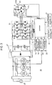
- FIG. 3 is a block diagram showing a control unit of the drum-type washing machine of this exemplary embodiment.
- control unit 16 has controller 17 including, for example, a microcomputer, which controls operations of motor 5, drainage pump 14, and feed valve 15, and the like, and successively controls a series of processes including a washing process, a rinsing process, and a dehydrating process.
- controller 17 including, for example, a microcomputer, which controls operations of motor 5, drainage pump 14, and feed valve 15, and the like, and successively controls a series of processes including a washing process, a rinsing process, and a dehydrating process.
- controller 17 carries out a display on display part 19 based on information input from input setting part 18 in order to set an operation course, and allows a user to be notified. Then, based on the operation course set by input setting part 18, a start of the operation of the washing machine is set. Specifically, when data are input from water level detection unit 30, lid opening/closing detection unit 31, and the like, into controller 17, actions of lid locking device 12, drainage pump 14, and feed valve 15 are controlled via switching part driving circuit 20 and switching part 21, and the washing operation is started.
- notifying part 25 carries out notification of the abnormality via controller 17.
- Controller 17 controls inverter 24 via inverter driving circuit 23 based on information from number-of-rotations detection unit 22 composed of position detection units 22a, 22b, and 22c for detecting a position of a rotor of motor 5 so as to control the rotation of motor 5.
- motor 5 includes, for example, a brushless DC motor, which includes a stator having a three-phase winding (not shown), and the rotor provided with a bipolar permanent magnet in a ring shape.
- the stator is configured by winding first winding 5a, second winding 5b, and third winding 5c, which constitute the three-phase winding, around an iron core having a slot.
- inverter 24 of control unit 16 is composed of U-phase, V-phase, and W-phase for driving motor 5.
- Each phase includes a switching element (switching part) having a parallel circuit of a power transistor (insulated gate bipolar transistor (IGBT)) and a reverse conducting diode.
- the U-phase of inverter 24 for driving motor 5 includes a serial circuit of first and second switching elements 24a and 24b; the V-phase includes a serial circuit of third and fourth switching elements 24c and 24d; and the W-phase includes a serial circuit of fifth and sixth switching elements 24e and 24f. Then, the U-phase, V-phase, and W-phase are connected in parallel so as to constitute inverter 24.
- the both ends of the serial circuit of each switching element constituting the U-phase, V-phase, and W-phase are connected to DC power supply by input terminals. Furthermore, a connecting point of two switching elements in the serial circuit of each switching element constituting the U-phase, V-phase, and W-phase is connected to the respective output terminal.
- the output terminal is connected to a U-phase terminal, a V-phase terminal, and a W-phase terminal of the three-phase winding of motor 5, controls and outputs the combination of ON and OFF of the two switching elements constituting the U-phase, V-phase, and W-phase of inverter 24.
- the U-phase terminal, V-phase terminal, and W-phase terminal of motor 5 achieve three states, i.e., a positive voltage, a zero voltage and a free (open) state.
- the combination of ON and OFF of the switching element is controlled by controller 17 by the following method based on the information from three position detection units 22a, 22b, and 22c configured by, for example, a Hall IC.
- Position detection units 22a, 22b, and 22c are disposed at the stator at intervals of an electrical angle of 120 degrees to face the permanent magnet provided in the rotor.
- each of three position detection units 22a, 22b, and 22c outputs a pulse at intervals of an electrical angle of 120 degrees.
- Controller 17 detects a time point at which any of signal states of three position detection units 22a, 22b, and 22c is changed.
- Controller 17 changes the combination of ON and OFF of first switching element 24a to sixth switching element 24f based on the detected signals of position detection units 22a, 22b, and 22c.
- the U-phase terminal, V-phase terminal, and W-phase terminal of motor 5 are made to be in three states, i.e., a positive voltage, a zero voltage and a free (open) state.
- the rotor of motor 5 is rotated by a magnetic field generated by electrification of first winding 5a, second winding 5b, and third winding 5c provided on the stator of motor 5.
- First switching element 24a, third switching element 24c and fifth switching element 24e of inverter 24 are pulse width modulation (PWM) controlled.
- controller 17 controls the number of rotations of the rotor of motor 5 by controlling the electrification ratio of high and low at a repetition frequency of, for example, 10 kHz. That is to say, controller 17 detects a cycle at which a state of a signal of any of three position detection units 22a, 22b, and 22c is changed, and calculates the number of rotations of the rotor of motor 5 from the detected cycle. Then, based on the calculated number of rotations, first switching element 24a, third switching element 24c and fifth switching element 24e of inverter 24 are PWM controlled so that the number of rotations of motor 5 is a set number of rotations.
- first switching element 24a to sixth switching element 24f of inverter 24 are PWM controlled so as to have torque in the rotation direction.
- first switching element 24a to sixth switching element 24f of inverter 24 are PWM controlled so as to have torque in the direction opposite to the rotation direction.
- commercial power supply 26 of control unit 16 is coupled to inverter 24 via DC power supply conversion device 27 including, for example, diode bridge 27a, smoothing capacitors 27b and 27c, and the like.
- control unit 16 of the drum-type washing machine in accordance with this exemplary embodiment is configured.
- control unit 16 is one example, and the configuration of brushless DC motor 5 and the configuration of inverter 24, and the like, are not limited to this configuration.
- FIG. 4 is a schematic view illustrating an operation display part of the drum-type washing machine in this exemplary embodiment.
- the operation display part includes at least input setting part 18 and display part 19.
- input setting part 18 of the operation display part includes washing time setting switch 18a for setting a washing time, number-of-rinsing-times setting switch 18b for setting a number of rinsing times, dehydrating time setting switch 18c for setting a dehydrating time, drying time setting switch 18d for setting a drying time, course setting switch 18e, start/pause switch 18f, power-on switch 18g, power-off switch 18h, and the like.
- display part 19 of the operation display part includes washing time display part 19a, number-of-rinsing-times display part 19b, dehydrating time display part 19c, drying time display part 19d, and course setting display part 19e, and the like.
- controller 17 locks lid 11 in a closed state or unlocks lid 11 by lid locking device 12 shown in FIG. 1 according to the setting of input setting part 18 of the operation display part (for example, in a state in which washing time setting switch 18a is turned on, and power-on switch 18g is turned on). Controller 17 makes it possible to carry out operation of the washing machine when lid 11 is locked by lid locking device 12.
- controller 17 controls so that lid locking device 12 continues to lock lid 11 in the closed state when the operation is temporarily stopped by the setting of input setting part 18, for example, start/pause switch 18f during operation of the washing machine. Furthermore, also after the operation of the washing machine is finished, controller 17 controls so that lid locking device 12 continues to lock lid 11 in the closed state.
- control actions detecting a case in which a belt is broken or a case in which a belt is disengaged are described with reference to FIGs. 5 to 7 .
- Control actions after detecting the case in which the belt is broken or the case in which the belt is disengaged are described with reference to FIGs. 8 and 9 .
- FIG. 5 is a first flowchart illustrating control before break of a belt or disengagement of a belt is detected in the drum-type washing machine of this exemplary embodiment.
- step S100 when the action of the washing machine is started (step S100), power-on switch 18g of input setting part 18 shown in FIG. 4 is pressed to be turned on (step S101).
- step S102 it is decided whether or not start/pause switch 18f of input setting part 18 is turned on. At this time, when start/pause switch 18f is turned off ("No" in step S102), the process waits until start/pause switch 18f is pressed.
- step S102 when start/pause switch 18f of input setting part 18 is pressed to be turned on ("Yes” in step S102), a washing process is started. At this time, lid 11 is controlled by lid locking device 12, and lid 11 is locked in a closed state (step S103).
- step S104 it is determined whether or not motor 5 starts a rotation action. At this time, when motor 5 does not start the rotation action ("No" in step S104), the process waits.
- step S104 when motor 5 starts the rotation action ("Yes” in step S104), it is determined whether or not a braking action is carried out during the rotation action of motor 5 (step S105). At this time, when the braking action is not carried out ("No" in step S105), the process waits.
- step S105 when the braking action is carried out ("Yes" in step S105), it is decided whether or not the number of rotations of the motor, which is detected by position detection units 22a, 22b, and 22c at the start of the braking action, is a first predetermined number of rotations (for example, 750 rpm (revolutions per minute)) or more (step S106). At this time, the number of rotations of motor 5 is less than the first predetermined number of rotations ("No" in step S106), the process waits.
- a first predetermined number of rotations for example, 750 rpm (revolutions per minute)
- the number of rotations of motor 5 is the first predetermined number of rotations or more ("Yes" in step S106), it is decided whether or not a stopping time of motor 5 from the start of braking operation to stopping is shorter than the first predetermined time (for example, one second) (step S107).
- the stopping time of motor 5 from the start of braking to stopping is longer than the first predetermined time ("No" in step S107)
- step S107 When the stopping time of motor 5 from the start of the braking action to stopping is shorter than the first predetermined time (for example, one second) ("Yes" in step S107), the disengagement of the belt or the break of the belt is detected (step S108).
- the first predetermined time for example, one second
- the above-mentioned first predetermined time is changed and controlled by the number of rotations of motor 5 at the start of braking.
- the first predetermined time is set to one second.
- the number of rotations of the motor at the start of braking is the first predetermined number of rotations 1350 rpm or more and less than the first predetermined number of rotations 1650 rpm, the first predetermined time is set to 1.5 seconds.
- the first predetermined time is set to 2 seconds.
- the first predetermined time is made to be longer when the number of rotations of motor 5 at the start of braking is larger than the first predetermined number of rotations as opposed to when the number of rotations of motor 5 is smaller than the first predetermined number of rotations.
- the first predetermined time and the number of rotations are not limited to the above-mentioned range, they may be arbitrarily set as long as they do not affect a detection action of the washing machine.
- FIG. 6 is a second flowchart illustrating control before break of a belt or disengagement of a belt is detected in the drum-type washing machine of this exemplary embodiment. As shown in FIG. 6 , since the operations from step S100 to step S104 are the same as those in the first flowchart shown in FIG. 5 , the description thereof is omitted.
- step S104 when motor 5 starts a rotation action ("Yes" in step S104), it is decided whether or not the number of rotations of the motor, which is detected by position detection units 22a, 22b, and 22c, is a second predetermined number of rotations (for example, 2000 rpm) or more (step S110). At this time, the number of rotations of motor 5 is less than the second predetermined number of rotations ("No" in step S110), it is not determined that the belt is disengaged or the belt is broken, and the process continues (step S112).
- a second predetermined number of rotations for example, 2000 rpm
- step S110 When the number of rotations of motor 5 is the second predetermined number of rotations or more ("Yes" in step S110), the disengagement of the belt or the break of the belt is detected (step S111).
- the controller easily determines that the belt is broken or the belt is disengaged, that is, the belt is disengaged from the drum pulley more easily.
- the controller it is possible to recognize the number of rotations of the motor at the time of normal operation in which failure of the motor due to high-speed rotation does not occur, or in which the break of the belt or the disengagement of the belt does not occur, and to prevent the wrong detection that the belt is broken or the belt is disengaged.
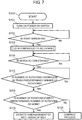
- FIG. 7 is a third flowchart illustrating control before break of a belt or disengagement of a belt is detected in the drum-type washing machine of this exemplary embodiment. As shown in FIG. 7 , since the operations from step S100 to step S104 are the same as those in the flowchart shown in FIG. 5 or FIG. 6 , the description thereof is omitted.
- step S104 when motor 5 starts a rotation action ("Yes" in step S104), it is decided whether or not the number of rotations of motor 5 for controlling to drive the rotation of rotary drum 1 is controlled by a third predetermined number of rotations (for example, 30 to 60 rpm (number of rotations of rotary drum 1) (step S113). At this time, when the number of rotations of motor 5 is not controlled by the third predetermined number of rotations ("No" in step S113), the process waits.
- a third predetermined number of rotations for example, 30 to 60 rpm (number of rotations of rotary drum 1)
- step S113 when the number of rotations of rotary drum 1 is controlled by the third predetermined number of rotations by the motor ("Yes" in step S113), it is decided whether or not the number of rotations of motor 5, which is detected by position detection units 22a, 22b, and 22c, is a fourth predetermined number of rotations (for example, 1000 rpm) or more (step S114). At this time, when the number of rotations of motor 5 is less than the fourth predetermined number of rotations ("No" in step S114), it is not determined that the belt is broken or the belt is disengaged, and each washing process is continuously executed according to the operation course (step S116).
- a fourth predetermined number of rotations for example, 1000 rpm
- step S114 When the number of rotations of motor 5 is the fourth predetermined number of rotations or more ("Yes" in step S114), the disengagement of the belt or the break of the belt is detected (step S115).
- the controller detects that motor 5 rotates faster than the fourth predetermined number of rotations in the case where motor 5 controls the rotation of rotary drum 1 to rotate at the third predetermined number of rotations, it determines that the belt is broken or the belt is disengaged, that is, the belt is disengaged from the drum pulley. As a result, it is possible to increase the opportunities for detecting the break of the belt or the disengagement of the belt.
- the fourth predetermined number of rotations of motor 5 for detecting the break of the belt or the disengagement of the belt is changed by the third predetermined number of rotations of motor 5 for controlling to drive the rotation of rotary drum 1.
- the fourth predetermined number of rotations of motor 5 is set to 1200 rpm.
- the fourth predetermined number of rotations of motor 5 is set to 1500 rpm.
- the fourth predetermined number of rotations of motor 5 is set to 2000 rpm.
- the values are not limited to the above-mentioned range as long as the relation that the fourth predetermined number of rotations of motor 5 is set to be larger as the third predetermined number of rotations of motor 5 for controlling to drive the rotation of rotary drum 1 becomes larger is secured.
- the value may be arbitrarily set as long as it does not affect the detection operation of the washing machine.
- FIG. 8 and 9 in order to facilitate the understanding of the determination at the time of detecting the break of the belt or the disengagement of the belt, the description is partially repeated.
- FIG. 8 is a fourth flowchart illustrating control after the break of the belt or the disengagement of the belt is detected in the drum-type washing machine of this exemplary embodiment.
- control after the break of the belt or the disengagement of the belt is detected in the drum-type washing machine is started (step S200).
- step S201 it is decided whether or not the break of the belt or the disengagement of the belt is detected. At this time, when the break of the belt or the disengagement of the belt is not detected ("No" in step S201), the process waits.
- a user is notified of an abnormality that the belt is broken or the belt is disengaged (step S202).
- examples of a method of notifying a user include notification with a sound generating device such as a beeper, notification by blinking display part 19, notification by displaying an error number such as a failure mode, and the like.
- step S203 it is determined whether or not a second predetermined time (for example, 5 minutes) has passed after detecting the break of the belt or the disengagement of the belt (step S203).
- a second predetermined time for example, 5 minutes
- the process waits until the second predetermined time has passed.
- lid locking device 12 continues to lock lid 11 in a closed state until the second predetermined time has passed. This is carried out to wait until the rotation by inertia of rotary drum 1 stops after the belt is broken or the belt is disengaged.
- lid locking device 12 controls to unlock the lid (step S204). This makes it possible to open lid 11 and to take out laundry and the like from rotary drum 1.
- the controller controls so that the locked state of the lid is maintained by lid locking device 12 until the second predetermined time has passed and the lid is unlocked by the lid locking device after the second predetermined time has passed.
- FIG. 9 is a fifth flowchart illustrating control after the break of the belt or the disengagement of the belt is detected in the drum-type washing machine of this exemplary embodiment. As shown in FIG. 9 , since the operations from step S200 to step S202 are the same as those in the flowchart shown in FIG. 8 , the description thereof is omitted.
- step S201 when the break of the belt or the disengagement of the belt is detected ("Yes” in step S201), a user is notified of an abnormality that the belt is broken or the belt is disengaged (step S202).
- step S205 it is determined whether or not power-off switch 18h of input setting part 18 is pressed to be turned on.
- step S205 When power-off switch 18h of input setting part 18 is turned on ("Yes” in step S205), power supply of a washing machine is not disconnected (not turned off), and the closed state of lid 11 is maintained by lid locking device 12 (step S206).
- a third predetermined time for example, 5 minutes
- step S207 the process waits until the third predetermined time has passed.
- lid locking device 12 continues to lock the closed state of lid 11 until the third predetermined time has passed. This is carried out to wait until the rotation by inertia of rotary drum 1 stops after the belt is broken or the belt is disengaged.
- lid locking device 12 controls to unlock the lid (step S208). This makes it possible to open lid 11 and to take out laundry and the like from rotary drum 1.
- step S209 the power supply of the washing machine is turned off.
- step S203 it is determined whether or not the second predetermined time (for example, 5 minutes) has passed after the break of the belt or the disengagement of the belt is detected (step S203).
- the process waits until the second predetermined time has passed.
- lid locking device 12 continues to lock lid 11 in a closed state until the second predetermined time has passed. This is carried out to wait until the rotation by inertia of rotary drum 1 stops after the belt is broken or the belt is disengaged.
- lid locking device 12 controls to unlock the lid (step S204). This makes it possible to open lid 11 and to take out laundry and the like from rotary drum 1.
- rotation shaft 4 is provided in substantially the horizontal direction (including the horizontal direction) of the rotation center of rotary drum 1, the direction of an axial center of rotary drum 1 may be provided in substantially the horizontal direction.
Landscapes
- Engineering & Computer Science (AREA)
- Textile Engineering (AREA)
- Control Of Washing Machine And Dryer (AREA)
- Main Body Construction Of Washing Machines And Laundry Dryers (AREA)
Claims (4)
- Trommelwaschmaschine, umfassend:eine Drehtrommel (1);einen Wassertank (3), der die Drehtrommel (1) umfasst;eine Trommelriemenscheibe (6), die sicher auf einer Drehachse (4) der Drehtrommel (1) angebracht ist;einen Motor (5), der an einem äußeren Bodenteil des Wassertanks (3) befestigt ist;einen Riemen (7), der Drehung des Motors auf die Trommelriemenscheibe (6) überträgt;eine Anzahl-von-Drehungen-Erfassungseinheit (22) zum Erfassen einer Anzahl von Drehungen des Motors (5);einen Deckel (11) zum Öffnen/Schließen eines Öffnungsteils der Drehtrommel (1);eine Deckelverriegelungsvorrichtung (12) zum Verriegeln des Deckels in einem geschlossenen Zustand; undeine Steuerung (17) zum Ausführen jedes Vorgangs von mindestens einem Waschvorgang, einem Spülvorgang und einem Entwässerungsvorgang,gekennzeichnet dadurch, dassdie Steuerung (17) eine Steuerung ausführt durch Bestimmen, dass der Riemen (7) defekt oder von der Trommelriemenscheibe (6) abgelöst ist nach einer Anhaltezeit vom Beginn eines Bremsvorgangs des Motors (5) bis zum Anhalten und der Anzahl von Drehungen des Motors (5), undwobei die Steuerung (17) bestimmt, dass der Riemen (7) entweder defekt oder von der Trommelriemenscheibe (6) abgelöst ist, wenn die Anhaltezeit des Motors (5) kürzer ist als eine erste vorbestimmte Zeit, wenn der Motor (5) gebremst wird.
- Trommelwaschmaschine nach Anspruch 1,
wobei die Steuerung (17) die erste vorbestimmte Zeit länger ausdehnt, wenn die Anzahl von Drehungen des Motors (5) größer ist als eine erste vorbestimmte Anzahl von Drehungen zu Beginn des Bremsens als wenn die Anzahl von Drehungen des Motors (5) kleiner ist als die erste vorbestimmte Anzahl von Drehungen. - Trommelwaschmaschine nach Anspruch 1 oder 2,
wobei die Steuerung (17) die Deckelverriegelungsvorrichtung (12) steuert, um den Deckel (11) zu verriegeln, bis eine zweite vorbestimmte Zeit vergangen ist, wenn der Riemen (7) als defekt oder abgelöst erfasst wird, und dann die Deckelverriegelungsvorrichtung (12) entriegelt, nachdem eine zweite vorbestimmte Zeit vergangen ist. - Trommelwaschmaschine nach einem der Ansprüche 1 bis 3,
wobei die Steuerung (17) eine eingeschaltete Einstellung aufrechterhält bis eine dritte vorbestimmte Zeit vergangen ist, wenn der Riemen (7) als defekt oder abgelöst erfasst wird, auch wenn die Steuerung (17) in einem Ausschaltvorgang ist, und die Stromversorgung ausschaltet, nachdem die dritte vorbestimmte Zeit vergangen ist.
Applications Claiming Priority (1)
| Application Number | Priority Date | Filing Date | Title |
|---|---|---|---|
| JP2010241647A JP5573596B2 (ja) | 2010-10-28 | 2010-10-28 | ドラム式洗濯機 |
Publications (3)
| Publication Number | Publication Date |
|---|---|
| EP2447407A2 EP2447407A2 (de) | 2012-05-02 |
| EP2447407A3 EP2447407A3 (de) | 2015-08-05 |
| EP2447407B1 true EP2447407B1 (de) | 2017-12-27 |
Family
ID=44720794
Family Applications (1)
| Application Number | Title | Priority Date | Filing Date |
|---|---|---|---|
| EP11184193.8A Not-in-force EP2447407B1 (de) | 2010-10-28 | 2011-10-06 | Trommelwaschmaschine |
Country Status (4)
| Country | Link |
|---|---|
| EP (1) | EP2447407B1 (de) |
| JP (1) | JP5573596B2 (de) |
| CN (1) | CN102465422B (de) |
| TW (1) | TWI461585B (de) |
Cited By (1)
| Publication number | Priority date | Publication date | Assignee | Title |
|---|---|---|---|---|
| EP3836371B1 (de) * | 2018-12-05 | 2025-09-10 | Askoll Holding S.r.l. a socio unico | Verbesserte motoranordnung für wäschetrocknermaschine und wäschetrocknermaschine mit besagter anordnung |
Families Citing this family (11)
| Publication number | Priority date | Publication date | Assignee | Title |
|---|---|---|---|---|
| JP6044811B2 (ja) * | 2013-02-27 | 2016-12-14 | 日立工機株式会社 | 携帯用電気かんな |
| CN104342877B (zh) * | 2013-08-08 | 2018-04-06 | 博西华电器(江苏)有限公司 | 衣物处理机 |
| CN106149283A (zh) * | 2015-04-28 | 2016-11-23 | 青岛海尔洗衣机有限公司 | 一种絮凝处理过程中搅拌机构故障判断方法及洗衣机 |
| JP6706738B2 (ja) * | 2017-02-22 | 2020-06-10 | パナソニックIpマネジメント株式会社 | ドラム式洗濯機 |
| CN107255565B (zh) * | 2017-08-07 | 2019-05-31 | 珠海格力电器股份有限公司 | 洗衣机皮带盘松动的检测方法和检测装置 |
| CN109537241B (zh) * | 2017-09-21 | 2021-02-23 | 松下家电(中国)有限公司 | 皮带脱落检测方法及洗衣机 |
| CN109440395B (zh) * | 2018-12-12 | 2021-03-19 | 无锡小天鹅电器有限公司 | 衣物处理装置及其电机皮带松动的提示方法与装置 |
| US11136705B2 (en) * | 2019-05-15 | 2021-10-05 | Haier Us Appliance Solutions, Inc. | Detecting mechanical decoupling in a laundry appliance |
| JP7460982B2 (ja) * | 2019-07-18 | 2024-04-03 | 青島海爾洗衣机有限公司 | 洗濯機 |
| CN112411115B (zh) | 2019-08-20 | 2022-06-10 | 佛山海尔滚筒洗衣机有限公司 | 一种洗涤设备及洗涤设备滚筒锁定的判定方法 |
| BE1029774B1 (de) * | 2021-09-15 | 2023-04-17 | Miele & Cie | Schlupferkennungsverfahren für eine Wäschebehandlungsmaschine und Wäschebehandlungsmaschine |
Family Cites Families (17)
| Publication number | Priority date | Publication date | Assignee | Title |
|---|---|---|---|---|
| JP2834855B2 (ja) * | 1990-06-26 | 1998-12-14 | 三洋電機株式会社 | ドラム式洗濯機 |
| JPH07299278A (ja) * | 1994-05-02 | 1995-11-14 | Matsushita Electric Ind Co Ltd | 脱水兼用洗濯機 |
| JP3152578B2 (ja) * | 1995-02-20 | 2001-04-03 | 三洋電機株式会社 | 回転ドラム式衣類乾燥機 |
| JP3568328B2 (ja) * | 1996-07-31 | 2004-09-22 | 三洋電機株式会社 | 衣類乾燥機 |
| JPH11114294A (ja) * | 1997-10-14 | 1999-04-27 | Toshiba Corp | 衣類乾燥機 |
| JPH11179099A (ja) * | 1997-12-17 | 1999-07-06 | Toshiba Corp | 衣類乾燥機 |
| CN100375814C (zh) * | 2002-07-12 | 2008-03-19 | 乐金电子(天津)电器有限公司 | 滚筒传动带折断的感知方法 |
| US6996920B2 (en) * | 2003-07-25 | 2006-02-14 | Lg Electronics Inc. | Control method and system for clothes dryer |
| JP3776908B2 (ja) * | 2003-11-28 | 2006-05-24 | 株式会社東芝 | ドラム式洗濯機 |
| CN1712628A (zh) * | 2004-06-14 | 2005-12-28 | 乐金电子(天津)电器有限公司 | 具备传动带断裂状态检测功能的烘干机以及其控制方法 |
| WO2007077113A1 (en) * | 2006-01-05 | 2007-07-12 | Arcelik Anonim Sirketi | A washer/ dryer |
| JP2007236719A (ja) * | 2006-03-10 | 2007-09-20 | Sanyo Electric Co Ltd | 衣類乾燥機 |
| JP2008068000A (ja) * | 2006-09-15 | 2008-03-27 | Sharp Corp | 洗濯機 |
| TR200900894T1 (tr) * | 2006-11-29 | 2009-06-22 | Ar�El�K Anon�M ��Rket� | Bir yıkayıcı/kurutucu |
| TR200904141T1 (tr) * | 2006-12-26 | 2009-10-21 | Ar�El�K Anon�M ��Rket� | Tahrik kayışı kopmasının algılandığı bir yıkayıcı/kurutucu. |
| JP4930485B2 (ja) * | 2008-10-10 | 2012-05-16 | パナソニック株式会社 | 洗濯機 |
| CN101736555B (zh) * | 2008-11-04 | 2013-02-20 | 海尔集团公司 | 滚筒洗衣机、洗干一体机电机皮带脱落检测方法 |
-
2010
- 2010-10-28 JP JP2010241647A patent/JP5573596B2/ja active Active
-
2011
- 2011-09-26 TW TW100134576A patent/TWI461585B/zh active
- 2011-10-06 EP EP11184193.8A patent/EP2447407B1/de not_active Not-in-force
- 2011-10-28 CN CN2011103375570A patent/CN102465422B/zh active Active
Cited By (1)
| Publication number | Priority date | Publication date | Assignee | Title |
|---|---|---|---|---|
| EP3836371B1 (de) * | 2018-12-05 | 2025-09-10 | Askoll Holding S.r.l. a socio unico | Verbesserte motoranordnung für wäschetrocknermaschine und wäschetrocknermaschine mit besagter anordnung |
Also Published As
| Publication number | Publication date |
|---|---|
| TW201217599A (en) | 2012-05-01 |
| CN102465422B (zh) | 2013-09-11 |
| JP5573596B2 (ja) | 2014-08-20 |
| CN102465422A (zh) | 2012-05-23 |
| JP2012090831A (ja) | 2012-05-17 |
| EP2447407A3 (de) | 2015-08-05 |
| EP2447407A2 (de) | 2012-05-02 |
| TWI461585B (zh) | 2014-11-21 |
Similar Documents
| Publication | Publication Date | Title |
|---|---|---|
| EP2447407B1 (de) | Trommelwaschmaschine | |
| EP1116812B1 (de) | Trommelwaschmaschine | |
| US20170327990A1 (en) | Washing machine and method of controlling the same | |
| KR20110045759A (ko) | 세탁기 및 세탁기의 제어방법 | |
| JP2008312387A (ja) | 洗濯機、洗濯乾燥機およびdcブラシレスモータ駆動回路 | |
| JP2014087511A (ja) | 洗濯機 | |
| JP2011050630A (ja) | ドラム式洗濯乾燥機 | |
| KR102229178B1 (ko) | 세탁기 및 그 제어방법 | |
| JP2005312570A (ja) | 洗濯機 | |
| JP2005254003A (ja) | ドラム式洗濯機 | |
| JP4457857B2 (ja) | 洗濯乾燥機 | |
| JP6698458B2 (ja) | 洗濯機 | |
| JP4846671B2 (ja) | 回転容器駆動装置及びその制御方法,洗濯機,乾燥機 | |
| JP6528082B2 (ja) | 洗濯機 | |
| JP6706738B2 (ja) | ドラム式洗濯機 | |
| JP7324971B2 (ja) | 洗濯機 | |
| TWI253486B (en) | Washing machine | |
| CN112411115A (zh) | 一种洗涤设备及洗涤设备滚筒锁定的判定方法 | |
| JP2020081459A (ja) | 洗濯機 | |
| JP4740921B2 (ja) | 洗濯機 | |
| KR101157831B1 (ko) | 세탁기의 오동작 방지방법 | |
| CN114174581A (zh) | 洗衣机 | |
| CN113802329A (zh) | 洗衣机 | |
| KR20060041370A (ko) | 누전 검출 기능을 갖는 응축식 건조기 | |
| KR20080057399A (ko) | 인버터 제어장치 및 방법 |
Legal Events
| Date | Code | Title | Description |
|---|---|---|---|
| PUAI | Public reference made under article 153(3) epc to a published international application that has entered the european phase |
Free format text: ORIGINAL CODE: 0009012 |
|
| AK | Designated contracting states |
Kind code of ref document: A2 Designated state(s): AL AT BE BG CH CY CZ DE DK EE ES FI FR GB GR HR HU IE IS IT LI LT LU LV MC MK MT NL NO PL PT RO RS SE SI SK SM TR |
|
| AX | Request for extension of the european patent |
Extension state: BA ME |
|
| PUAL | Search report despatched |
Free format text: ORIGINAL CODE: 0009013 |
|
| AK | Designated contracting states |
Kind code of ref document: A3 Designated state(s): AL AT BE BG CH CY CZ DE DK EE ES FI FR GB GR HR HU IE IS IT LI LT LU LV MC MK MT NL NO PL PT RO RS SE SI SK SM TR |
|
| AX | Request for extension of the european patent |
Extension state: BA ME |
|
| RIC1 | Information provided on ipc code assigned before grant |
Ipc: D06F 37/42 20060101ALI20150629BHEP Ipc: D06F 58/08 20060101ALI20150629BHEP Ipc: D06F 58/28 20060101ALI20150629BHEP Ipc: D06F 37/22 20060101AFI20150629BHEP Ipc: D06F 37/30 20060101ALI20150629BHEP Ipc: D06F 33/02 20060101ALI20150629BHEP |
|
| 17P | Request for examination filed |
Effective date: 20151222 |
|
| RBV | Designated contracting states (corrected) |
Designated state(s): AL AT BE BG CH CY CZ DE DK EE ES FI FR GB GR HR HU IE IS IT LI LT LU LV MC MK MT NL NO PL PT RO RS SE SI SK SM TR |
|
| GRAP | Despatch of communication of intention to grant a patent |
Free format text: ORIGINAL CODE: EPIDOSNIGR1 |
|
| GRAJ | Information related to disapproval of communication of intention to grant by the applicant or resumption of examination proceedings by the epo deleted |
Free format text: ORIGINAL CODE: EPIDOSDIGR1 |
|
| RIC1 | Information provided on ipc code assigned before grant |
Ipc: D06F 58/08 20060101ALI20160907BHEP Ipc: D06F 58/28 20060101ALI20160907BHEP Ipc: D06F 33/02 20060101ALI20160907BHEP Ipc: D06F 37/22 20060101AFI20160907BHEP Ipc: D06F 37/30 20060101ALI20160907BHEP Ipc: D06F 37/42 20060101ALI20160907BHEP |
|
| GRAP | Despatch of communication of intention to grant a patent |
Free format text: ORIGINAL CODE: EPIDOSNIGR1 |
|
| GRAJ | Information related to disapproval of communication of intention to grant by the applicant or resumption of examination proceedings by the epo deleted |
Free format text: ORIGINAL CODE: EPIDOSDIGR1 |
|
| INTG | Intention to grant announced |
Effective date: 20161007 |
|
| GRAP | Despatch of communication of intention to grant a patent |
Free format text: ORIGINAL CODE: EPIDOSNIGR1 |
|
| STAA | Information on the status of an ep patent application or granted ep patent |
Free format text: STATUS: GRANT OF PATENT IS INTENDED |
|
| GRAJ | Information related to disapproval of communication of intention to grant by the applicant or resumption of examination proceedings by the epo deleted |
Free format text: ORIGINAL CODE: EPIDOSDIGR1 |
|
| STAA | Information on the status of an ep patent application or granted ep patent |
Free format text: STATUS: REQUEST FOR EXAMINATION WAS MADE |
|
| INTG | Intention to grant announced |
Effective date: 20161020 |
|
| GRAJ | Information related to disapproval of communication of intention to grant by the applicant or resumption of examination proceedings by the epo deleted |
Free format text: ORIGINAL CODE: EPIDOSDIGR1 |
|
| GRAP | Despatch of communication of intention to grant a patent |
Free format text: ORIGINAL CODE: EPIDOSNIGR1 |
|
| INTC | Intention to grant announced (deleted) | ||
| GRAP | Despatch of communication of intention to grant a patent |
Free format text: ORIGINAL CODE: EPIDOSNIGR1 |
|
| STAA | Information on the status of an ep patent application or granted ep patent |
Free format text: STATUS: GRANT OF PATENT IS INTENDED |
|
| INTG | Intention to grant announced |
Effective date: 20161104 |
|
| INTC | Intention to grant announced (deleted) | ||
| INTG | Intention to grant announced |
Effective date: 20161128 |
|
| INTG | Intention to grant announced |
Effective date: 20161128 |
|
| GRAJ | Information related to disapproval of communication of intention to grant by the applicant or resumption of examination proceedings by the epo deleted |
Free format text: ORIGINAL CODE: EPIDOSDIGR1 |
|
| GRAP | Despatch of communication of intention to grant a patent |
Free format text: ORIGINAL CODE: EPIDOSNIGR1 |
|
| INTG | Intention to grant announced |
Effective date: 20170718 |
|
| GRAS | Grant fee paid |
Free format text: ORIGINAL CODE: EPIDOSNIGR3 |
|
| GRAA | (expected) grant |
Free format text: ORIGINAL CODE: 0009210 |
|
| STAA | Information on the status of an ep patent application or granted ep patent |
Free format text: STATUS: THE PATENT HAS BEEN GRANTED |
|
| AK | Designated contracting states |
Kind code of ref document: B1 Designated state(s): AL AT BE BG CH CY CZ DE DK EE ES FI FR GB GR HR HU IE IS IT LI LT LU LV MC MK MT NL NO PL PT RO RS SE SI SK SM TR |
|
| REG | Reference to a national code |
Ref country code: GB Ref legal event code: FG4D |
|
| REG | Reference to a national code |
Ref country code: CH Ref legal event code: EP |
|
| REG | Reference to a national code |
Ref country code: AT Ref legal event code: REF Ref document number: 958386 Country of ref document: AT Kind code of ref document: T Effective date: 20180115 |
|
| REG | Reference to a national code |
Ref country code: IE Ref legal event code: FG4D |
|
| REG | Reference to a national code |
Ref country code: DE Ref legal event code: R096 Ref document number: 602011044521 Country of ref document: DE |
|
| PG25 | Lapsed in a contracting state [announced via postgrant information from national office to epo] |
Ref country code: NO Free format text: LAPSE BECAUSE OF FAILURE TO SUBMIT A TRANSLATION OF THE DESCRIPTION OR TO PAY THE FEE WITHIN THE PRESCRIBED TIME-LIMIT Effective date: 20180327 Ref country code: FI Free format text: LAPSE BECAUSE OF FAILURE TO SUBMIT A TRANSLATION OF THE DESCRIPTION OR TO PAY THE FEE WITHIN THE PRESCRIBED TIME-LIMIT Effective date: 20171227 Ref country code: LT Free format text: LAPSE BECAUSE OF FAILURE TO SUBMIT A TRANSLATION OF THE DESCRIPTION OR TO PAY THE FEE WITHIN THE PRESCRIBED TIME-LIMIT Effective date: 20171227 |
|
| REG | Reference to a national code |
Ref country code: NL Ref legal event code: MP Effective date: 20171227 |
|
| REG | Reference to a national code |
Ref country code: LT Ref legal event code: MG4D |
|
| REG | Reference to a national code |
Ref country code: AT Ref legal event code: MK05 Ref document number: 958386 Country of ref document: AT Kind code of ref document: T Effective date: 20171227 |
|
| PG25 | Lapsed in a contracting state [announced via postgrant information from national office to epo] |
Ref country code: LV Free format text: LAPSE BECAUSE OF FAILURE TO SUBMIT A TRANSLATION OF THE DESCRIPTION OR TO PAY THE FEE WITHIN THE PRESCRIBED TIME-LIMIT Effective date: 20171227 Ref country code: GR Free format text: LAPSE BECAUSE OF FAILURE TO SUBMIT A TRANSLATION OF THE DESCRIPTION OR TO PAY THE FEE WITHIN THE PRESCRIBED TIME-LIMIT Effective date: 20180328 Ref country code: RS Free format text: LAPSE BECAUSE OF FAILURE TO SUBMIT A TRANSLATION OF THE DESCRIPTION OR TO PAY THE FEE WITHIN THE PRESCRIBED TIME-LIMIT Effective date: 20171227 Ref country code: HR Free format text: LAPSE BECAUSE OF FAILURE TO SUBMIT A TRANSLATION OF THE DESCRIPTION OR TO PAY THE FEE WITHIN THE PRESCRIBED TIME-LIMIT Effective date: 20171227 Ref country code: BG Free format text: LAPSE BECAUSE OF FAILURE TO SUBMIT A TRANSLATION OF THE DESCRIPTION OR TO PAY THE FEE WITHIN THE PRESCRIBED TIME-LIMIT Effective date: 20180327 |
|
| PG25 | Lapsed in a contracting state [announced via postgrant information from national office to epo] |
Ref country code: NL Free format text: LAPSE BECAUSE OF FAILURE TO SUBMIT A TRANSLATION OF THE DESCRIPTION OR TO PAY THE FEE WITHIN THE PRESCRIBED TIME-LIMIT Effective date: 20171227 |
|
| PG25 | Lapsed in a contracting state [announced via postgrant information from national office to epo] |
Ref country code: SK Free format text: LAPSE BECAUSE OF FAILURE TO SUBMIT A TRANSLATION OF THE DESCRIPTION OR TO PAY THE FEE WITHIN THE PRESCRIBED TIME-LIMIT Effective date: 20171227 Ref country code: ES Free format text: LAPSE BECAUSE OF FAILURE TO SUBMIT A TRANSLATION OF THE DESCRIPTION OR TO PAY THE FEE WITHIN THE PRESCRIBED TIME-LIMIT Effective date: 20171227 Ref country code: EE Free format text: LAPSE BECAUSE OF FAILURE TO SUBMIT A TRANSLATION OF THE DESCRIPTION OR TO PAY THE FEE WITHIN THE PRESCRIBED TIME-LIMIT Effective date: 20171227 Ref country code: CZ Free format text: LAPSE BECAUSE OF FAILURE TO SUBMIT A TRANSLATION OF THE DESCRIPTION OR TO PAY THE FEE WITHIN THE PRESCRIBED TIME-LIMIT Effective date: 20171227 Ref country code: CY Free format text: LAPSE BECAUSE OF FAILURE TO SUBMIT A TRANSLATION OF THE DESCRIPTION OR TO PAY THE FEE WITHIN THE PRESCRIBED TIME-LIMIT Effective date: 20171227 |
|
| PG25 | Lapsed in a contracting state [announced via postgrant information from national office to epo] |
Ref country code: SM Free format text: LAPSE BECAUSE OF FAILURE TO SUBMIT A TRANSLATION OF THE DESCRIPTION OR TO PAY THE FEE WITHIN THE PRESCRIBED TIME-LIMIT Effective date: 20171227 Ref country code: IS Free format text: LAPSE BECAUSE OF FAILURE TO SUBMIT A TRANSLATION OF THE DESCRIPTION OR TO PAY THE FEE WITHIN THE PRESCRIBED TIME-LIMIT Effective date: 20180427 Ref country code: PL Free format text: LAPSE BECAUSE OF FAILURE TO SUBMIT A TRANSLATION OF THE DESCRIPTION OR TO PAY THE FEE WITHIN THE PRESCRIBED TIME-LIMIT Effective date: 20171227 Ref country code: AT Free format text: LAPSE BECAUSE OF FAILURE TO SUBMIT A TRANSLATION OF THE DESCRIPTION OR TO PAY THE FEE WITHIN THE PRESCRIBED TIME-LIMIT Effective date: 20171227 Ref country code: RO Free format text: LAPSE BECAUSE OF FAILURE TO SUBMIT A TRANSLATION OF THE DESCRIPTION OR TO PAY THE FEE WITHIN THE PRESCRIBED TIME-LIMIT Effective date: 20171227 Ref country code: IT Free format text: LAPSE BECAUSE OF FAILURE TO SUBMIT A TRANSLATION OF THE DESCRIPTION OR TO PAY THE FEE WITHIN THE PRESCRIBED TIME-LIMIT Effective date: 20171227 |
|
| REG | Reference to a national code |
Ref country code: DE Ref legal event code: R097 Ref document number: 602011044521 Country of ref document: DE |
|
| PLBE | No opposition filed within time limit |
Free format text: ORIGINAL CODE: 0009261 |
|
| STAA | Information on the status of an ep patent application or granted ep patent |
Free format text: STATUS: NO OPPOSITION FILED WITHIN TIME LIMIT |
|
| PG25 | Lapsed in a contracting state [announced via postgrant information from national office to epo] |
Ref country code: DK Free format text: LAPSE BECAUSE OF FAILURE TO SUBMIT A TRANSLATION OF THE DESCRIPTION OR TO PAY THE FEE WITHIN THE PRESCRIBED TIME-LIMIT Effective date: 20171227 |
|
| 26N | No opposition filed |
Effective date: 20180928 |
|
| PG25 | Lapsed in a contracting state [announced via postgrant information from national office to epo] |
Ref country code: SI Free format text: LAPSE BECAUSE OF FAILURE TO SUBMIT A TRANSLATION OF THE DESCRIPTION OR TO PAY THE FEE WITHIN THE PRESCRIBED TIME-LIMIT Effective date: 20171227 |
|
| REG | Reference to a national code |
Ref country code: CH Ref legal event code: PL |
|
| GBPC | Gb: european patent ceased through non-payment of renewal fee |
Effective date: 20181006 |
|
| REG | Reference to a national code |
Ref country code: BE Ref legal event code: MM Effective date: 20181031 |
|
| PG25 | Lapsed in a contracting state [announced via postgrant information from national office to epo] |
Ref country code: MC Free format text: LAPSE BECAUSE OF FAILURE TO SUBMIT A TRANSLATION OF THE DESCRIPTION OR TO PAY THE FEE WITHIN THE PRESCRIBED TIME-LIMIT Effective date: 20171227 Ref country code: LU Free format text: LAPSE BECAUSE OF NON-PAYMENT OF DUE FEES Effective date: 20181006 |
|
| REG | Reference to a national code |
Ref country code: IE Ref legal event code: MM4A |
|
| PG25 | Lapsed in a contracting state [announced via postgrant information from national office to epo] |
Ref country code: FR Free format text: LAPSE BECAUSE OF NON-PAYMENT OF DUE FEES Effective date: 20181031 Ref country code: BE Free format text: LAPSE BECAUSE OF NON-PAYMENT OF DUE FEES Effective date: 20181031 Ref country code: CH Free format text: LAPSE BECAUSE OF NON-PAYMENT OF DUE FEES Effective date: 20181031 Ref country code: LI Free format text: LAPSE BECAUSE OF NON-PAYMENT OF DUE FEES Effective date: 20181031 |
|
| PG25 | Lapsed in a contracting state [announced via postgrant information from national office to epo] |
Ref country code: GB Free format text: LAPSE BECAUSE OF NON-PAYMENT OF DUE FEES Effective date: 20181006 Ref country code: IE Free format text: LAPSE BECAUSE OF NON-PAYMENT OF DUE FEES Effective date: 20181006 |
|
| PG25 | Lapsed in a contracting state [announced via postgrant information from national office to epo] |
Ref country code: MT Free format text: LAPSE BECAUSE OF NON-PAYMENT OF DUE FEES Effective date: 20181006 |
|
| PGFP | Annual fee paid to national office [announced via postgrant information from national office to epo] |
Ref country code: DE Payment date: 20191021 Year of fee payment: 9 |
|
| PG25 | Lapsed in a contracting state [announced via postgrant information from national office to epo] |
Ref country code: TR Free format text: LAPSE BECAUSE OF FAILURE TO SUBMIT A TRANSLATION OF THE DESCRIPTION OR TO PAY THE FEE WITHIN THE PRESCRIBED TIME-LIMIT Effective date: 20171227 |
|
| PG25 | Lapsed in a contracting state [announced via postgrant information from national office to epo] |
Ref country code: PT Free format text: LAPSE BECAUSE OF FAILURE TO SUBMIT A TRANSLATION OF THE DESCRIPTION OR TO PAY THE FEE WITHIN THE PRESCRIBED TIME-LIMIT Effective date: 20171227 |
|
| PG25 | Lapsed in a contracting state [announced via postgrant information from national office to epo] |
Ref country code: MK Free format text: LAPSE BECAUSE OF NON-PAYMENT OF DUE FEES Effective date: 20171227 Ref country code: HU Free format text: LAPSE BECAUSE OF FAILURE TO SUBMIT A TRANSLATION OF THE DESCRIPTION OR TO PAY THE FEE WITHIN THE PRESCRIBED TIME-LIMIT; INVALID AB INITIO Effective date: 20111006 Ref country code: SE Free format text: LAPSE BECAUSE OF FAILURE TO SUBMIT A TRANSLATION OF THE DESCRIPTION OR TO PAY THE FEE WITHIN THE PRESCRIBED TIME-LIMIT Effective date: 20171227 |
|
| PG25 | Lapsed in a contracting state [announced via postgrant information from national office to epo] |
Ref country code: AL Free format text: LAPSE BECAUSE OF FAILURE TO SUBMIT A TRANSLATION OF THE DESCRIPTION OR TO PAY THE FEE WITHIN THE PRESCRIBED TIME-LIMIT Effective date: 20171227 |
|
| REG | Reference to a national code |
Ref country code: DE Ref legal event code: R119 Ref document number: 602011044521 Country of ref document: DE |
|
| PG25 | Lapsed in a contracting state [announced via postgrant information from national office to epo] |
Ref country code: DE Free format text: LAPSE BECAUSE OF NON-PAYMENT OF DUE FEES Effective date: 20210501 |