EP2447579B1 - Selbsttätig schließende Rückschlagklappe - Google Patents
Selbsttätig schließende Rückschlagklappe Download PDFInfo
- Publication number
- EP2447579B1 EP2447579B1 EP11007380.6A EP11007380A EP2447579B1 EP 2447579 B1 EP2447579 B1 EP 2447579B1 EP 11007380 A EP11007380 A EP 11007380A EP 2447579 B1 EP2447579 B1 EP 2447579B1
- Authority
- EP
- European Patent Office
- Prior art keywords
- valve disc
- seat ring
- valve
- longitudinal axis
- disc
- Prior art date
- Legal status (The legal status is an assumption and is not a legal conclusion. Google has not performed a legal analysis and makes no representation as to the accuracy of the status listed.)
- Not-in-force
Links
Images

Classifications
-
- F—MECHANICAL ENGINEERING; LIGHTING; HEATING; WEAPONS; BLASTING
- F16—ENGINEERING ELEMENTS AND UNITS; GENERAL MEASURES FOR PRODUCING AND MAINTAINING EFFECTIVE FUNCTIONING OF MACHINES OR INSTALLATIONS; THERMAL INSULATION IN GENERAL
- F16K—VALVES; TAPS; COCKS; ACTUATING-FLOATS; DEVICES FOR VENTING OR AERATING
- F16K15/00—Check valves
- F16K15/02—Check valves with guided rigid valve members
- F16K15/03—Check valves with guided rigid valve members with a hinged closure member or with a pivoted closure member
Definitions
- the invention relates to an automatically closing non-return valve for flowing pressure media, having a arranged in a circular passage opening of a valve body disc, which is provided at its outer periphery with a sealing surface which cooperates with a matching sealing surface of a located on the inside of the passage opening sealing ring the closing plane defined by the outer periphery of the valve disc and the inner periphery of the seat ring is inclined to a plane orthogonal to the longitudinal axis of the passage opening and the disc is pivotally mounted about an axis crossing the passage opening located above the longitudinal axis of the passage opening and above the valve disc, such that the disc is pivoted by the pressure of the flowing pressure medium in the open position and by their own weight from the open position to the closed position f falls.
- the invention proposes, starting from the check valve of the type mentioned above, that the sealing surface on the outer circumference of the valve disc and the matching sealing surface on the inner circumference of the seat ring are formed in the circumferential direction so oval that they are the shape of a lateral surface of a leaning Have truncated cone and can be mapped in this lateral surface a host of levels, of which at least one in the projection on the orthogonal to the longitudinal axis of the Passage opening extending plane is circular or deviates from the circular shape such that the quotient of small axis a and large axis b is greater than 0.98.
- valve disc and the seat ring makes it possible to increase the clear width of the passage opening in the region of the seat ring relative to the prior art considerably, and indeed largely independent of the inclination of the closing plane.
- an increase in the clear width in the specified range of up to 20% can be achieved.
- a particularly preferred embodiment of the invention provides that the sealing surfaces of the valve disc and seat ring are made of metal.
- the exclusively made of metal seal pairing is important in that the sealing surfaces of the disc and seat ring are constantly exposed to the flowing pressure medium and its temperatures.
- Metallic seals are less susceptible to jamming, seizing or sticking and can be easily opened and closed at any time.
- the sealing surfaces of the valve disc and seat ring are appropriately finished. Such finely machined sealing surfaces result in an absolutely tight closure, largely independent of the pressure difference and the nature of the pressure medium.
- the sealing surfaces of the disc and / or seat ring are also hardened beyond.
- a valve body is designated by the reference numeral 1.
- the flap housing 1 is internally provided with a passage opening 2, which has a circular cross section and whose longitudinal axis is designated by the reference numeral 3.
- a seat ring 4 attached, which is provided at its inner periphery with a sealing surface 5.
- a flap disc 6 is disposed in the passage opening 2 of the housing 1, which is provided at its outer periphery with a sealing surface 7 and which is mounted about the passage opening 2 of the valve body 1 transverse pivot axis 8 pivotally mounted on the valve body 1.
- the inner circumference of the seat ring 4 and the outer periphery of the valve disc 6 located in the closed position jointly define a closing plane X, which is inclined relative to a plane Y orthogonal to the longitudinal axis 3 of the passage opening 2.
- the pivot axis 8 is arranged above the longitudinal axis 3 of the passage opening 2 and above the valve disc 6, that the disc 6 falls by its own weight in the illustrated closed position and lifted by the pressure of flowing in the flow direction S pressure medium from this closed position and pivoted into the open position becomes. So that the valve disc 6 closes automatically, the closing plane X must extend obliquely to the longitudinal axis 3 of the valve housing 1, wherein the oblique angle ⁇ between the closing plane X and the longitudinal axis 3 of the valve body 1 is less than 52 °.
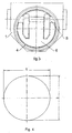
- the special feature of the invention is that, as from the FIGS. 1 and 4 can be seen, the sealing surface 7 on the outer circumference of the valve disc 6 and the matching sealing surface 5 on the inner circumference of the seat ring 4 in the circumferential direction are formed oval such that they have the shape of a lateral surface of an oblique truncated cone and mapped in this lateral surface a bevy of levels leaves, of which at least one in the projection on the orthogonal to the longitudinal axis (3) of the passage opening (2) extending plane (Y) is circular or so deviates from the circular shape that the quotient of the small axis a and large axis b greater than 0.98.
- This ensures that the released from the seat ring 4 clear width of the passage opening assumes a maximum value, regardless of the inclination of the closing level X against the orthogonal to the longitudinal axis 3 of the passage opening extending plane Y.
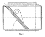
- FIG. 5 shows a vertical longitudinal section through the valve body 1, wherein the closing plane X and the longitudinal axis 3 of the valve body 1 are inclined to each other.
- the bevel angle ⁇ must be less than 52 °.
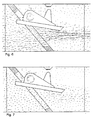
- FIGS. 6 and 7 the particular advantage of the invention due to the changed flap geometry.
- the flow is represented by arrows.
- the number of arrows is identical in both figures.
- the length of the arrows is a measure of the flow velocity.
- the FIG. 6 shows that with the same diameter of the passage opening of the housing in the old flap geometry, the flow velocity is greater than in FIG. 7 , This results in a significantly higher flow resistance. Higher flow velocities result in a greater pressure loss.
- the new flap geometry according to the teaching of the invention in FIG. 7 allows a higher flow, because the inside width is increased by 20%.
Landscapes
- Engineering & Computer Science (AREA)
- General Engineering & Computer Science (AREA)
- Mechanical Engineering (AREA)
- Check Valves (AREA)
- Lift Valve (AREA)
Description
- Die Erfindung betrifft eine selbsttätig schließende Rückschlagklappe für fließende Druckmedien, mit einer in einer kreisrunden Durchtrittsöffnung eines Klappengehäuses angeordneten Klappenscheibe, die an ihrem äußeren Umfang mit einer Dichtfläche versehen ist, die mit einer dazu passenden Dichtfläche eines an der Innenseite der Durchtrittsöffnung befindlichen Dichtringes zusammenwirkt, wobei die durch den Außenumfang der Klappenscheibe und den Innenumfang des Sitzringes definierte Schließebene geneigt gegen eine orthogonal zur Längsachse der Durchtrittsöffnung verlaufenden Ebene verläuft und die Klappenscheibe um eine die Durchtrittsöffnung querende Achse verschwenkbar gelagert ist, die oberhalb der Längsachse der Durchtrittsöffnung und Oberhalb der Klappenscheibe angeordnet ist, derart, dass die Klappenscheibe vom Druck des durchfließenden Druckmediums in die Offenstellung verschwenkt wird und durch ihr Eigengewicht aus der Offenstellung in die Schließstellung fällt.
- Derartige Schrägsitz-Rückschlagklappen sind nach dem Stand der Technik bekannt und werden in erster Linie in der Dampfzuführung von Dampfturbinen eingesetzt, um diese bei Abfall der Last schnell absperren zu können. In diesem Fall besteht nämlich die Gefahr, dass die im Dampfzuführungssystem gespeicherte Energie die Dampfturbine auf unzulässig hohe Drehzahlen beschleunigt, wenn die Dampfzufuhr nicht sehr schnell unterbrochen wird. Ein ähnliches Problem gibt es bei großen Kompressoranlagen, bei denen das aus dem Druckluftnetz zurückströmende Druckmedium den Kompressor auf unzulässig hohe Drehzahlen beschleunigen kann, wenn dessen Antrieb ausfällt. In diesem Fall verhindert die schnell schließende Schrägsitz-Rückschlagklappe in der Druckleitung das Zurückströmen von Druckmedium zum Kompressor hin.
- Ein wichtiger Vorteil einer solchen Schrägsitz-Rückschlagklappe gegenüber Rückschlagklappen mit orthogonal zur Längsachse der Durchtrittsöffnung verlaufenden Schließebene besteht darin, dass der von der Klappenscheibe von der Offenstellung in die Schließstellung zurückzulegende Winkelweg wegen der Schräglage der Schließebene erheblich verkürzt ist, sodass die Klappenscheibe sehr schnell und leichtgängig von der Offenstellung in die Schließstellung fällt. Dabei ist der Winkelweg von der Offenstellung in die Schließstellung umso kürzer, je größer die Neigung der Schließebene gegen die orthogonal zur Längsachse der Durchtrittsöffnung verlaufende Ebene ist. Dieser Vergrößerung des Neigungswinkels der Schließebene sind aber dadurch Grenzen gesetzt, dass sowohl die Dichtfläche am Außenumfang der Klappenscheibe als auch die Dichtfläche am Innenumfang des Sitzringes in ihrer Umfangsrichtung kreisrund sind, so dass der an der Innenseite des Gehäuses befindliche Sitzring infolge seiner kreisrunden Gestalt die lichte Weite der Durchtrittsöffnung im Bereich des Sitzringes einengt, wobei diese Einengung mit jeder Vergrößerung der oben erläuterten Neigung der Schließebene zunimmt. Diese Verkleinerung der lichten Weite im Bereich des Sitzringes führt zu einer Drosselung des durchtretenden Druckmediums und damit zu unerwünschten Energieverlusten.
- Es ist Aufgabe der Erfindung, die Rückschlagklappe der eingangs genannten Art dahingehend weiterzubilden, dass unter Beibehaltung der lichten Weite der Durchtrittsöffnung des Klappengehäuses die in der Öffnungsstellung erreichbare lichte Weite im Bereich des Sitzringes vergrößert wird, und zwar möglichst unabhängig von der Neigung der Schließebene.
- Zur Lösung dieser Aufgabe schlägt die Erfindung ausgehend von der Rückschlagklappe der eingangs genannten Art vor, dass die Dichtfläche am äußeren Umfang der Klappenscheibe und die dazu passende Dichtfläche am inneren Umfang des Sitzringes in Umfangsrichtung derart oval ausgebildet sind, dass sie die Form einer Mantelfläche eines schiefen Kegelstumpfes aufweisen und sich in dieser Mantelfläche eine Schar von Ebenen abbilden lässt, von denen wenigstens eine in der Projektion auf die orthogonal zur Längsachse der Durchtrittsöffnung verlaufenden Ebene kreisrund ist oder derart von der Kreisform abweicht, dass der Quotient aus kleiner Achse a und großer Achse b größer als 0,98 ist.
- Durch diese Ausgestaltung der Klappenscheibe und des Sitzringes gelingt es, die lichte Weite der Durchtrittsöffnung im Bereich des Sitzringes gegenüber dem Stand der Technik erheblich zu vergrößern, und zwar weitgehend unabhängig von der Neigung der Schließebene. Versuche haben ergeben, dass nach der Lehre der Erfindung eine Vergrößerung der lichten Weite in dem angegebenen Bereich von bis zu 20 % erreichbar ist.
- Durch die ovale Form der Dichtflächen von Klappenscheibe und Sitzring wird zwar eine geometrisch komplizierte Bearbeitung der Dichtflächen erforderlich, was allerdings mit modernen Bearbeitungseinrichtungen keine besonderen Schwierigkeiten mehr bedeutet.
- Eine besonders bevorzugte Ausführungsform der Erfindung sieht vor, dass die Dichtflächen von Klappenscheibe und Sitzring aus Metall bestehen. Die ausschließlich aus Metall bestehende Dichtungspaarung ist insofern wichtig, als die Dichtflächen von Klappenscheibe und Sitzring ständig dem durchströmenden Druckmedium und dessen Temperaturen ausgesetzt sind. Metallische Dichtungen neigen weniger zum Verklemmen, Festfressen oder Verkleben und sind jederzeit leichtgängig zu öffnen und zu schließen.
- Zur Verbesserung der Dichtwirkung sind die Dichtflächen von Klappenscheibe und Sitzring zweckmäßig feinbearbeitet. Solche feinbearbeiteten Dichtflächen führen zu einem absolut dichten Verschluss, und zwar weitgehend unabhängig von der Druckdifferenz und der Beschaffenheit des Druckmediums.
- Um den beim schnellen Zuschlagen der Klappenscheibe unvermeidlich auftretenden Schlägen und Stößen ohne Beschädigung besser standhalten zu können, sind die Dichtflächen von Klappenscheibe und /oder Sitzring darüber hinaus gehärtet.
- Ein Ausführungsbeispiel der Erfindung wird im Folgenden anhand der Zeichnung näher erläutert. Es zeigen:
- Figur 1:
- Eine erfindungsgemäß ausgebildete Rückschlagklappe und deren Gehäuse in einem vertikalen Längsschnitt durch das Gehäuse;
- Figur 2:
- die Rückschlagklappe und das Gehäuse gemäß
Figur 1 in einem horizontalen Längsschnitt; - Figur 3:
- eine Ansicht zu
Figur 1 in Strömungsrichtung des Druckmediums; - Figur 4:
- die Projektion einer der Dichtflächen von Klappenscheibe und Sitzring auf eine orthogonal zur Längsachse der Durchtrittsöffnung des Gehäuses verlaufende Ebene, wobei der Quotient aus kleiner Ellipsenachse a und großer Ellipsenachse b größer als 0,98 ist;
- Figur 5:
- Darstellung des Schrägenwinkels α zwischen der Schließebene und der Längsachse des Gehäuses in einem vertikalen Längsschnitt durch das Gehäuse;
- Figur 6:
- Darstellung des Strömungswiderstandes nach Stand der Technik;
- Figur 7:
- Darstellung des Strömungswiderstandes nach Lehre der Erfindung, nach der die lichte Weite um 20 % vergrößert ist;
- In der Zeichnung ist ein Klappengehäuse mit dem Bezugszeichen 1 bezeichnet. Das Klappengehäuse 1 ist innen mit einer Durchtrittsöffnung 2 versehen, die einen kreisrunden Querschnitt hat und deren Längsachse mit dem Bezugszeichen 3 bezeichnet ist. Am inneren Umfang der Durchtrittsöffnung 2 ist ein Sitzring 4 befestigt, der an seinem inneren Umfang mit einer Dichtfläche 5 versehen ist.
- Weiterhin ist in der Durchtrittsöffnung 2 des Gehäuses 1 eine Klappenscheibe 6 angeordnet, die an ihrem äußeren Umfang mit einer Dichtfläche 7 versehen ist und die um eine die Durchtrittsöffnung 2 des Klappengehäuses 1 querende Schwenkachse 8 verschwenkbar an dem Klappengehäuse 1 gelagert ist. Der innere Umfang des Sitzringes 4 und der äußere Umfang der in der Schließstellung befindlichen Klappenscheibe 6 definieren gemeinsam eine Schließebene X, die gegen eine orthogonal zur Längsachse 3 der Durchtrittsöffnung 2 verlaufende Ebene Y geneigt verläuft. In der dargestellten Schließstellung liegen die beiden zusammenpassenden Dichtflächen 5 und 7 des Sitzringes 4 und der Klappenscheibe 6, die beide aus Metall bestehen, feinbearbeitet und gehärtet sind, dichtend aneinander an.
- Die Schwenkachse 8 ist derart oberhalb der Längsachse 3 der Durchtrittsöffnung 2 und oberhalb der Klappenscheibe 6 angeordnet, dass die Klappenscheibe 6 durch ihr Eigengewicht in die dargestellte Schließstellung fällt und durch den Druck des in Strömungsrichtung S durchströmenden Druckmediums aus dieser Schließstellung herausgehoben und in die Offenstellung verschwenkt wird. Damit die Klappenscheibe 6 selbstständig schließt, muss die Schließebene X schräg zur Längsachse 3 des Klappengehäuses 1 verlaufen, wobei der Schrägenwinkel α zwischen der Schließebene X und der Längsachse 3 des Klappengehäuses 1 kleiner als 52° ist.
- Die Besonderheit der Erfindung besteht darin, dass, wie aus den
Figuren 1 und4 ersichtlich, die Dichtfläche 7 am äußeren Umfang der Klappenscheibe 6 und die dazu passende Dichtfläche 5 am inneren Umfang des Sitzringes 4 in Umfangsrichtung derart oval ausgebildet sind, dass sie die Form einer Mantelfläche eines schiefen Kegelstumpfes aufweisen und sich in dieser Mantelfläche eine Schar von Ebenen abbilden lässt, von denen wenigstens eine in der Projektion auf die orthogonal zur Längsachse (3) der Durchtrittsöffnung (2) verlaufenden Ebene (Y) kreisrund ist oder derart von der Kreisform abweicht, dass der Quotient aus kleiner Achse a und großer Achse b größer als 0,98 ist. Hierdurch wird erreicht, dass die vom Sitzring 4 freigelassene lichte Weite der Durchtrittsöffnung einen maximalen Wert annimmt, und zwar unabhängig von der Neigung der Schließebene X gegen die orthogonal zur Längsachse 3 der Durchtrittsöffnung verlaufende Ebene Y. - Die
Figur 5 zeigt einen vertikalen Längsschnitt durch das Klappengehäuse 1, wobei die Schließebene X und die Längsachse 3 des Klappengehäuses 1 schräg zueinander stehen. Um die selbstschließende Eigenschaft der Rückschlagklappe sicherzustellen, muss der Schrägenwinkel α kleiner als 52° sein. - Ferner verdeutlicht die Gegenüberstellung der
Figuren 6 und 7 den besonderen Vorteil der Erfindung infolge der veränderten Klappengeometrie. In beiden Figuren wird die Strömung durch Pfeile dargestellt. Die Anzahl der Pfeile ist in beiden Figuren identisch. Die Länge der Pfeile ist ein Maß für die Strömungsgeschwindigkeit. DieFigur 6 zeigt, dass bei gleichem Durchmesser der Durchtrittsöffnung des Gehäuses bei der alten Klappengeometrie die Strömungsgeschwindigkeit größer ist als inFigur 7 . Daraus resultiert ein bedeutend höherer Strömungswiderstand. Aus höheren Strömungsgeschwindigkeiten ergibt sich ein größerer Druckverlust. Die neue Klappengeometrie nach Lehre der Erfindung inFigur 7 ermöglicht einen höheren Durchfluss, weil die lichte Weite um 20 % vergrößert ist.
Claims (5)
- Selbsttätig schließende Rückschlagklappe für fließende Druckmedien, mit einer in einer kreisrunderi Durchtrittsöffnung (2) eines Klappengehäuses (1) angeordneten Klappenscheibe (6), die an ihrem äußeren Umfang mit einer Dichtfläche (7) versehen ist, die mit einer dazu passenden Dichtfläche (5) eines an der Innenseite der Durchtrittsöffnung (2) befindlichen Sitzringes (4) zusammenwirkt, wobei die durch den Außenumfang der Klappenscheibe (6) und den Innenumfang des Sitzringes (4) definierte Schließebene (X) geneigt gegen eine orthogonal zur Längsachse (3) der Durchtrittsöffnung (2) verlaufenden Ebene (Y) verläuft und die Klappenscheibe (6) um eine die Durchtrittsöffnung (2) querende Schwenkachse (8) verschwenkbar gelagert ist, die oberhalb der Längsachse (3) der Durchtrittsöffnung (2) und oberhalb der Klappenscheibe (6) angeordnet ist, derart, dass die Klappenscheibe (6) durch ihr Eigengewicht aus der Offenstellung in die Schließstellung fällt, wobei die Dichtfläche (7) am äußeren Umfang der Klappenscheibe (6) und die dazu passende Dichtfläche (5) am inneren Umfang des Sitzringes (4) in Umfangsrichtung derart oval ausgebildet sind, dass sie die Form einer Mantelfläche eines schiefen Kegelstumpfes aufweisen und sich in dieser Mantelfläche eine Schar von Ebenen abbilden lässt, dadurch gekennzeichnet, dass von diesen Ebenen wenigstens eine in der Projektion auf die orthogonal zur Längsachse (3) der Durchtrittsöffnung (2) verlaufenden Ebene (Y) kreisrund ist oder derart von der Kreisform abweicht, dass der Quotient aus kleiner Achse a und großer Achse b größer als 0,98 ist.
- Rückschlagklappe nach Anspruch 1, dadurch gekennzeichnet, dass die Dichtflächen (5, 7) von Klappenscheibe (6) und Sitzring (4) aus Metall bestehen.
- Rückschlagklappe nach den Ansprüchen 1 und 2, dadurch gekennzeichnet, dass die Dichtflächen (7, 5) von Klappenscheibe (6) und Sitzring (4) feinbearbeitet sind.
- Rückschlagklappe nach den Ansprüchen 1 bis 3, dadurch gekennzeichnet, dass die Dichtflächen (7, 5) von Klappenscheibe (6) und/oder Sitzring (4) gehärtet sind.
- Rückschlagklappe nach den Ansprüchen 1 bis 4, dadurch gekennzeichnet, dass die Schließebene (X) schräg zur Längsachse (3) des Klappengehäuses(1) verläuft und der Schrägenwinkel (a) zwischen der Schließebene (X) und der Längsachse (3) des Klappengehäuses (1) kleiner als 52° ist.
Applications Claiming Priority (1)
| Application Number | Priority Date | Filing Date | Title |
|---|---|---|---|
| DE102010049665 | 2010-10-26 |
Publications (3)
| Publication Number | Publication Date |
|---|---|
| EP2447579A2 EP2447579A2 (de) | 2012-05-02 |
| EP2447579A3 EP2447579A3 (de) | 2013-05-15 |
| EP2447579B1 true EP2447579B1 (de) | 2014-11-19 |
Family
ID=44644886
Family Applications (1)
| Application Number | Title | Priority Date | Filing Date |
|---|---|---|---|
| EP11007380.6A Not-in-force EP2447579B1 (de) | 2010-10-26 | 2011-09-09 | Selbsttätig schließende Rückschlagklappe |
Country Status (2)
| Country | Link |
|---|---|
| EP (1) | EP2447579B1 (de) |
| ES (1) | ES2530966T3 (de) |
Family Cites Families (3)
| Publication number | Priority date | Publication date | Assignee | Title |
|---|---|---|---|---|
| US2763287A (en) * | 1952-11-15 | 1956-09-18 | Crane Co | Swing check valve |
| JPS5349332A (en) * | 1976-10-16 | 1978-05-04 | Kubota Ltd | Butterfly valve |
| US5305787A (en) * | 1993-02-03 | 1994-04-26 | C & S Valve Company | Disk valve with improved disk mounting |
-
2011
- 2011-09-09 EP EP11007380.6A patent/EP2447579B1/de not_active Not-in-force
- 2011-09-09 ES ES11007380T patent/ES2530966T3/es active Active
Also Published As
| Publication number | Publication date |
|---|---|
| EP2447579A2 (de) | 2012-05-02 |
| EP2447579A3 (de) | 2013-05-15 |
| ES2530966T3 (es) | 2015-03-09 |
Similar Documents
| Publication | Publication Date | Title |
|---|---|---|
| DE2916984A1 (de) | Sitz fuer ein absperrelement eines absperrorgans und absperrorgan mit einem solchen sitz | |
| DE112008002746T5 (de) | Ventilelementmechanismus für ein Abgaszirkulationsventil | |
| DE2005592A1 (de) | Absperrorgan mit Druckausgleichseinrichtung | |
| DE2433937C2 (de) | Rückschlagventil | |
| DE19728562C2 (de) | Regelbarer Kugelhahn | |
| DE202007018740U1 (de) | Doppelsitzventil | |
| CH645442A5 (de) | Selbstreinigendes ventil. | |
| DE6931306U (de) | Drehschuetz- oder drosselklappenventil. | |
| DE3013201A1 (de) | Absperrventil | |
| EP3994381A1 (de) | Ventilgehäuse und hubventil zum steuern einer prozessfluidströmung mit einem ventilgehäuse | |
| DE3815404C2 (de) | Schwenkklappenanordnung für Heißgas-Rohrleitungen | |
| DE19959109B4 (de) | Drehklappenventil | |
| DE19720566C1 (de) | Doppelsitzventil | |
| DE102014108379A1 (de) | Absperrvorrichtung | |
| DE102013010123A1 (de) | Armatur zum Absperren oder Regeln eines Mediums | |
| EP3470586B1 (de) | Absperrorgan zur verwendung in einem hydranten, hydrant und hauptventilsitz | |
| DE102009015184B4 (de) | Klappenventil | |
| WO2022002370A1 (de) | Klappenventil | |
| EP2447579A2 (de) | Selbsttätig schließende Rückschlagklappe | |
| DE307827C (de) | ||
| DE937502C (de) | Spreizdruckventil | |
| DE102008052855A1 (de) | Kugelhahn und Kugelküken | |
| DE8909262U1 (de) | Armaturengehäuse | |
| DE102012006569A1 (de) | Ventil | |
| DE102013222764A1 (de) | Rückschlagventil |
Legal Events
| Date | Code | Title | Description |
|---|---|---|---|
| PUAI | Public reference made under article 153(3) epc to a published international application that has entered the european phase |
Free format text: ORIGINAL CODE: 0009012 |
|
| AK | Designated contracting states |
Kind code of ref document: A2 Designated state(s): AL AT BE BG CH CY CZ DE DK EE ES FI FR GB GR HR HU IE IS IT LI LT LU LV MC MK MT NL NO PL PT RO RS SE SI SK SM TR |
|
| AX | Request for extension of the european patent |
Extension state: BA ME |
|
| PUAL | Search report despatched |
Free format text: ORIGINAL CODE: 0009013 |
|
| AK | Designated contracting states |
Kind code of ref document: A3 Designated state(s): AL AT BE BG CH CY CZ DE DK EE ES FI FR GB GR HR HU IE IS IT LI LT LU LV MC MK MT NL NO PL PT RO RS SE SI SK SM TR |
|
| AX | Request for extension of the european patent |
Extension state: BA ME |
|
| RIC1 | Information provided on ipc code assigned before grant |
Ipc: F16K 15/03 20060101AFI20130411BHEP |
|
| 17P | Request for examination filed |
Effective date: 20130614 |
|
| GRAP | Despatch of communication of intention to grant a patent |
Free format text: ORIGINAL CODE: EPIDOSNIGR1 |
|
| INTG | Intention to grant announced |
Effective date: 20131016 |
|
| GRAP | Despatch of communication of intention to grant a patent |
Free format text: ORIGINAL CODE: EPIDOSNIGR1 |
|
| INTG | Intention to grant announced |
Effective date: 20140716 |
|
| GRAS | Grant fee paid |
Free format text: ORIGINAL CODE: EPIDOSNIGR3 |
|
| GRAA | (expected) grant |
Free format text: ORIGINAL CODE: 0009210 |
|
| AK | Designated contracting states |
Kind code of ref document: B1 Designated state(s): AL AT BE BG CH CY CZ DE DK EE ES FI FR GB GR HR HU IE IS IT LI LT LU LV MC MK MT NL NO PL PT RO RS SE SI SK SM TR |
|
| REG | Reference to a national code |
Ref country code: GB Ref legal event code: FG4D Free format text: NOT ENGLISH |
|
| REG | Reference to a national code |
Ref country code: CH Ref legal event code: EP |
|
| REG | Reference to a national code |
Ref country code: AT Ref legal event code: REF Ref document number: 697231 Country of ref document: AT Kind code of ref document: T Effective date: 20141215 |
|
| REG | Reference to a national code |
Ref country code: IE Ref legal event code: FG4D Free format text: LANGUAGE OF EP DOCUMENT: GERMAN |
|
| REG | Reference to a national code |
Ref country code: DE Ref legal event code: R096 Ref document number: 502011004998 Country of ref document: DE Effective date: 20141231 |
|
| REG | Reference to a national code |
Ref country code: ES Ref legal event code: FG2A Ref document number: 2530966 Country of ref document: ES Kind code of ref document: T3 Effective date: 20150309 |
|
| REG | Reference to a national code |
Ref country code: NL Ref legal event code: VDEP Effective date: 20141119 |
|
| REG | Reference to a national code |
Ref country code: LT Ref legal event code: MG4D |
|
| PG25 | Lapsed in a contracting state [announced via postgrant information from national office to epo] |
Ref country code: IS Free format text: LAPSE BECAUSE OF FAILURE TO SUBMIT A TRANSLATION OF THE DESCRIPTION OR TO PAY THE FEE WITHIN THE PRESCRIBED TIME-LIMIT Effective date: 20150319 Ref country code: NO Free format text: LAPSE BECAUSE OF FAILURE TO SUBMIT A TRANSLATION OF THE DESCRIPTION OR TO PAY THE FEE WITHIN THE PRESCRIBED TIME-LIMIT Effective date: 20150219 Ref country code: NL Free format text: LAPSE BECAUSE OF FAILURE TO SUBMIT A TRANSLATION OF THE DESCRIPTION OR TO PAY THE FEE WITHIN THE PRESCRIBED TIME-LIMIT Effective date: 20141119 Ref country code: FI Free format text: LAPSE BECAUSE OF FAILURE TO SUBMIT A TRANSLATION OF THE DESCRIPTION OR TO PAY THE FEE WITHIN THE PRESCRIBED TIME-LIMIT Effective date: 20141119 Ref country code: PT Free format text: LAPSE BECAUSE OF FAILURE TO SUBMIT A TRANSLATION OF THE DESCRIPTION OR TO PAY THE FEE WITHIN THE PRESCRIBED TIME-LIMIT Effective date: 20150319 Ref country code: LT Free format text: LAPSE BECAUSE OF FAILURE TO SUBMIT A TRANSLATION OF THE DESCRIPTION OR TO PAY THE FEE WITHIN THE PRESCRIBED TIME-LIMIT Effective date: 20141119 |
|
| PG25 | Lapsed in a contracting state [announced via postgrant information from national office to epo] |
Ref country code: HR Free format text: LAPSE BECAUSE OF FAILURE TO SUBMIT A TRANSLATION OF THE DESCRIPTION OR TO PAY THE FEE WITHIN THE PRESCRIBED TIME-LIMIT Effective date: 20141119 Ref country code: SE Free format text: LAPSE BECAUSE OF FAILURE TO SUBMIT A TRANSLATION OF THE DESCRIPTION OR TO PAY THE FEE WITHIN THE PRESCRIBED TIME-LIMIT Effective date: 20141119 Ref country code: PL Free format text: LAPSE BECAUSE OF FAILURE TO SUBMIT A TRANSLATION OF THE DESCRIPTION OR TO PAY THE FEE WITHIN THE PRESCRIBED TIME-LIMIT Effective date: 20141119 Ref country code: LV Free format text: LAPSE BECAUSE OF FAILURE TO SUBMIT A TRANSLATION OF THE DESCRIPTION OR TO PAY THE FEE WITHIN THE PRESCRIBED TIME-LIMIT Effective date: 20141119 Ref country code: CY Free format text: LAPSE BECAUSE OF FAILURE TO SUBMIT A TRANSLATION OF THE DESCRIPTION OR TO PAY THE FEE WITHIN THE PRESCRIBED TIME-LIMIT Effective date: 20141119 Ref country code: RS Free format text: LAPSE BECAUSE OF FAILURE TO SUBMIT A TRANSLATION OF THE DESCRIPTION OR TO PAY THE FEE WITHIN THE PRESCRIBED TIME-LIMIT Effective date: 20141119 Ref country code: GR Free format text: LAPSE BECAUSE OF FAILURE TO SUBMIT A TRANSLATION OF THE DESCRIPTION OR TO PAY THE FEE WITHIN THE PRESCRIBED TIME-LIMIT Effective date: 20150220 |
|
| PG25 | Lapsed in a contracting state [announced via postgrant information from national office to epo] |
Ref country code: SK Free format text: LAPSE BECAUSE OF FAILURE TO SUBMIT A TRANSLATION OF THE DESCRIPTION OR TO PAY THE FEE WITHIN THE PRESCRIBED TIME-LIMIT Effective date: 20141119 Ref country code: DK Free format text: LAPSE BECAUSE OF FAILURE TO SUBMIT A TRANSLATION OF THE DESCRIPTION OR TO PAY THE FEE WITHIN THE PRESCRIBED TIME-LIMIT Effective date: 20141119 Ref country code: EE Free format text: LAPSE BECAUSE OF FAILURE TO SUBMIT A TRANSLATION OF THE DESCRIPTION OR TO PAY THE FEE WITHIN THE PRESCRIBED TIME-LIMIT Effective date: 20141119 Ref country code: RO Free format text: LAPSE BECAUSE OF FAILURE TO SUBMIT A TRANSLATION OF THE DESCRIPTION OR TO PAY THE FEE WITHIN THE PRESCRIBED TIME-LIMIT Effective date: 20141119 Ref country code: CZ Free format text: LAPSE BECAUSE OF FAILURE TO SUBMIT A TRANSLATION OF THE DESCRIPTION OR TO PAY THE FEE WITHIN THE PRESCRIBED TIME-LIMIT Effective date: 20141119 |
|
| REG | Reference to a national code |
Ref country code: DE Ref legal event code: R097 Ref document number: 502011004998 Country of ref document: DE |
|
| REG | Reference to a national code |
Ref country code: FR Ref legal event code: PLFP Year of fee payment: 5 |
|
| PLBE | No opposition filed within time limit |
Free format text: ORIGINAL CODE: 0009261 |
|
| STAA | Information on the status of an ep patent application or granted ep patent |
Free format text: STATUS: NO OPPOSITION FILED WITHIN TIME LIMIT |
|
| 26N | No opposition filed |
Effective date: 20150820 |
|
| PGFP | Annual fee paid to national office [announced via postgrant information from national office to epo] |
Ref country code: CH Payment date: 20150918 Year of fee payment: 5 Ref country code: DE Payment date: 20150922 Year of fee payment: 5 Ref country code: ES Payment date: 20150928 Year of fee payment: 5 Ref country code: GB Payment date: 20150917 Year of fee payment: 5 |
|
| PGFP | Annual fee paid to national office [announced via postgrant information from national office to epo] |
Ref country code: FR Payment date: 20150922 Year of fee payment: 5 |
|
| PGFP | Annual fee paid to national office [announced via postgrant information from national office to epo] |
Ref country code: IT Payment date: 20150924 Year of fee payment: 5 |
|
| PG25 | Lapsed in a contracting state [announced via postgrant information from national office to epo] |
Ref country code: SI Free format text: LAPSE BECAUSE OF FAILURE TO SUBMIT A TRANSLATION OF THE DESCRIPTION OR TO PAY THE FEE WITHIN THE PRESCRIBED TIME-LIMIT Effective date: 20141119 |
|
| PG25 | Lapsed in a contracting state [announced via postgrant information from national office to epo] |
Ref country code: LU Free format text: LAPSE BECAUSE OF FAILURE TO SUBMIT A TRANSLATION OF THE DESCRIPTION OR TO PAY THE FEE WITHIN THE PRESCRIBED TIME-LIMIT Effective date: 20150909 Ref country code: MC Free format text: LAPSE BECAUSE OF FAILURE TO SUBMIT A TRANSLATION OF THE DESCRIPTION OR TO PAY THE FEE WITHIN THE PRESCRIBED TIME-LIMIT Effective date: 20141119 |
|
| REG | Reference to a national code |
Ref country code: IE Ref legal event code: MM4A |
|
| PG25 | Lapsed in a contracting state [announced via postgrant information from national office to epo] |
Ref country code: IE Free format text: LAPSE BECAUSE OF NON-PAYMENT OF DUE FEES Effective date: 20150909 |
|
| PG25 | Lapsed in a contracting state [announced via postgrant information from national office to epo] |
Ref country code: MT Free format text: LAPSE BECAUSE OF FAILURE TO SUBMIT A TRANSLATION OF THE DESCRIPTION OR TO PAY THE FEE WITHIN THE PRESCRIBED TIME-LIMIT Effective date: 20141119 |
|
| REG | Reference to a national code |
Ref country code: DE Ref legal event code: R119 Ref document number: 502011004998 Country of ref document: DE |
|
| REG | Reference to a national code |
Ref country code: CH Ref legal event code: PL |
|
| GBPC | Gb: european patent ceased through non-payment of renewal fee |
Effective date: 20160909 |
|
| PG25 | Lapsed in a contracting state [announced via postgrant information from national office to epo] |
Ref country code: BG Free format text: LAPSE BECAUSE OF FAILURE TO SUBMIT A TRANSLATION OF THE DESCRIPTION OR TO PAY THE FEE WITHIN THE PRESCRIBED TIME-LIMIT Effective date: 20141119 Ref country code: HU Free format text: LAPSE BECAUSE OF FAILURE TO SUBMIT A TRANSLATION OF THE DESCRIPTION OR TO PAY THE FEE WITHIN THE PRESCRIBED TIME-LIMIT; INVALID AB INITIO Effective date: 20110909 Ref country code: SM Free format text: LAPSE BECAUSE OF FAILURE TO SUBMIT A TRANSLATION OF THE DESCRIPTION OR TO PAY THE FEE WITHIN THE PRESCRIBED TIME-LIMIT Effective date: 20141119 |
|
| REG | Reference to a national code |
Ref country code: FR Ref legal event code: ST Effective date: 20170531 |
|
| PG25 | Lapsed in a contracting state [announced via postgrant information from national office to epo] |
Ref country code: BE Free format text: LAPSE BECAUSE OF NON-PAYMENT OF DUE FEES Effective date: 20150930 Ref country code: GB Free format text: LAPSE BECAUSE OF NON-PAYMENT OF DUE FEES Effective date: 20160909 Ref country code: FR Free format text: LAPSE BECAUSE OF NON-PAYMENT OF DUE FEES Effective date: 20160930 Ref country code: LI Free format text: LAPSE BECAUSE OF NON-PAYMENT OF DUE FEES Effective date: 20160930 Ref country code: CH Free format text: LAPSE BECAUSE OF NON-PAYMENT OF DUE FEES Effective date: 20160930 Ref country code: DE Free format text: LAPSE BECAUSE OF NON-PAYMENT OF DUE FEES Effective date: 20170401 |
|
| PG25 | Lapsed in a contracting state [announced via postgrant information from national office to epo] |
Ref country code: TR Free format text: LAPSE BECAUSE OF FAILURE TO SUBMIT A TRANSLATION OF THE DESCRIPTION OR TO PAY THE FEE WITHIN THE PRESCRIBED TIME-LIMIT Effective date: 20141119 Ref country code: IT Free format text: LAPSE BECAUSE OF NON-PAYMENT OF DUE FEES Effective date: 20160909 |
|
| REG | Reference to a national code |
Ref country code: AT Ref legal event code: MM01 Ref document number: 697231 Country of ref document: AT Kind code of ref document: T Effective date: 20160909 |
|
| PG25 | Lapsed in a contracting state [announced via postgrant information from national office to epo] |
Ref country code: AT Free format text: LAPSE BECAUSE OF NON-PAYMENT OF DUE FEES Effective date: 20160909 |
|
| PG25 | Lapsed in a contracting state [announced via postgrant information from national office to epo] |
Ref country code: ES Free format text: LAPSE BECAUSE OF NON-PAYMENT OF DUE FEES Effective date: 20160910 |
|
| REG | Reference to a national code |
Ref country code: ES Ref legal event code: FD2A Effective date: 20180628 |
|
| PG25 | Lapsed in a contracting state [announced via postgrant information from national office to epo] |
Ref country code: MK Free format text: LAPSE BECAUSE OF FAILURE TO SUBMIT A TRANSLATION OF THE DESCRIPTION OR TO PAY THE FEE WITHIN THE PRESCRIBED TIME-LIMIT Effective date: 20141119 |
|
| PG25 | Lapsed in a contracting state [announced via postgrant information from national office to epo] |
Ref country code: AL Free format text: LAPSE BECAUSE OF FAILURE TO SUBMIT A TRANSLATION OF THE DESCRIPTION OR TO PAY THE FEE WITHIN THE PRESCRIBED TIME-LIMIT Effective date: 20141119 |