EP2447586B1 - Raccord pour tuyau - Google Patents
Raccord pour tuyau Download PDFInfo
- Publication number
- EP2447586B1 EP2447586B1 EP11186778.4A EP11186778A EP2447586B1 EP 2447586 B1 EP2447586 B1 EP 2447586B1 EP 11186778 A EP11186778 A EP 11186778A EP 2447586 B1 EP2447586 B1 EP 2447586B1
- Authority
- EP
- European Patent Office
- Prior art keywords
- line
- hose coupling
- socket
- coupling according
- base body
- Prior art date
- Legal status (The legal status is an assumption and is not a legal conclusion. Google has not performed a legal analysis and makes no representation as to the accuracy of the status listed.)
- Active
Links
Images

Classifications
-
- F—MECHANICAL ENGINEERING; LIGHTING; HEATING; WEAPONS; BLASTING
- F16—ENGINEERING ELEMENTS AND UNITS; GENERAL MEASURES FOR PRODUCING AND MAINTAINING EFFECTIVE FUNCTIONING OF MACHINES OR INSTALLATIONS; THERMAL INSULATION IN GENERAL
- F16L—PIPES; JOINTS OR FITTINGS FOR PIPES; SUPPORTS FOR PIPES, CABLES OR PROTECTIVE TUBING; MEANS FOR THERMAL INSULATION IN GENERAL
- F16L33/00—Arrangements for connecting hoses to rigid members; Rigid hose-connectors, i.e. single members engaging both hoses
- F16L33/22—Arrangements for connecting hoses to rigid members; Rigid hose-connectors, i.e. single members engaging both hoses with means not mentioned in the preceding groups for gripping the hose between inner and outer parts
- F16L33/223—Arrangements for connecting hoses to rigid members; Rigid hose-connectors, i.e. single members engaging both hoses with means not mentioned in the preceding groups for gripping the hose between inner and outer parts the sealing surfaces being pressed together by means of a member, e.g. a swivel nut, screwed on or into one of the joint parts
-
- A—HUMAN NECESSITIES
- A61—MEDICAL OR VETERINARY SCIENCE; HYGIENE
- A61M—DEVICES FOR INTRODUCING MEDIA INTO, OR ONTO, THE BODY; DEVICES FOR TRANSDUCING BODY MEDIA OR FOR TAKING MEDIA FROM THE BODY; DEVICES FOR PRODUCING OR ENDING SLEEP OR STUPOR
- A61M39/00—Tubes, tube connectors, tube couplings, valves, access sites or the like, specially adapted for medical use
- A61M39/10—Tube connectors; Tube couplings
- A61M39/12—Tube connectors; Tube couplings for joining a flexible tube to a rigid attachment
-
- F—MECHANICAL ENGINEERING; LIGHTING; HEATING; WEAPONS; BLASTING
- F16—ENGINEERING ELEMENTS AND UNITS; GENERAL MEASURES FOR PRODUCING AND MAINTAINING EFFECTIVE FUNCTIONING OF MACHINES OR INSTALLATIONS; THERMAL INSULATION IN GENERAL
- F16L—PIPES; JOINTS OR FITTINGS FOR PIPES; SUPPORTS FOR PIPES, CABLES OR PROTECTIVE TUBING; MEANS FOR THERMAL INSULATION IN GENERAL
- F16L47/00—Connecting arrangements or other fittings specially adapted to be made of plastics or to be used with pipes made of plastics
- F16L47/04—Connecting arrangements or other fittings specially adapted to be made of plastics or to be used with pipes made of plastics with a swivel nut or collar engaging the pipe
Definitions
- the invention relates to a hose coupling made of plastic consisting of a base body and a closure body for tightly connecting a hose or pipe, wherein the base body at least one coaxial to a central axis M in the body extending and expiring in a pipe socket with a mouth channel and a coaxial to the central axis M arranged around the pipe socket housing portion and an optional, formed between the channel and the housing portion, arranged coaxially to the central axis M and open towards the mouth annular gap has.
- the closure body has a coaxial with the central axis M arranged through opening for passing a line and a manual screwing trained operating part.
- the main body and the closure body each have at least one acting in a direction parallel to the central axis M stop surface and the two abutment surfaces are visible after connecting the hose or pipe from the outside medium or directly in an end position E to each other.
- a gap is formed, which is visible at least until the closed state of the body and closure body in an end position E from outside the hose coupling.
- the gap extending parallel to the stop surfaces has the advantage that the slightest deviations in the range of a few tenths of a millimeter before the closed position can be detected with the naked eye.
- connection nipple for plastic pipes with a arranged at one end of the connecting nipple cone ring described which has an inner cone.
- a collet-like design, displaceable in the cone ring clamping sleeve made of resilient material is provided, the nipple pointing end is divided by several longitudinal slots in a plurality of resilient collet arms and having free ends on its inner side of the pipe holding edges. The retaining edges interact with their outer sides with the inner cone of the cone ring.
- a fitting on the pipe O-ring is arranged such that when inserting the tube into the collet, the collet arms are spread outwards, their retaining edges penetrate under the action of the restoring force of the resilient collet arms in the pipe wall and the Hold the pipe automatically.
- the tube of the cone ring is designed as a screw-on the nipple union nut, the operating position is fixed by an axial stop.
- the DE 80 08 838 U1 also realizes the clamping principle without damaging the hose or pipe.
- the pipe socket is surrounded at its base at a distance of about the hose thickness of a ring with external thread having an inner cone.
- the coupling sleeve is with a cooperating with the external thread Internal thread and formed to this concentric inner ring.
- the outer diameter of the inner ring is smaller than the mouth of the inner cone of the tube stub surrounding the ring.
- A1 DE-OS-1-A discloses a device for connecting to one end of a tubular conduit, having a main body having a longitudinal axis, and a clamping element by means of which the conduit is releasably fixable to the device.
- the base body on a nipple, on which the line can be pushed and to which the line is fixed.
- the device has a defined end position for the clamping element when clamping the line, which is maintained even in the case of a further actuation of an actuating element of the device, so that an overload of the clamping element or the line is prevented.
- the clamping tongues may have on their outer surface a further portion which is aligned in the line clamping the deflected state of the clamping tongues substantially cylindrical to the longitudinal axis of the body, and cooperates with the actuating element such that upon further actuation of the actuating element, the clamping tongues radially are not further deflected in the direction of the line.
- the clamping tongues and thus the clamping means are deflected only in a predeterminable extent in the direction of the line, so that a defined end position of the clamping tongues is given with respect to the line. It can therefore not come to an overuse of the line, which could be detrimental to a permanent sealing effect.
- the invention has for its object to form a hose coupling and to arrange so that a precise tensile strength of the connection to the line without cutting the line and at the same time a simple production of the hose coupling is achieved.
- the object is achieved according to the invention in that the closure body a subsequent to the passage opening in axial Richtun which depending on Ausfatun in the annular gap for connecting the line can be inserted and applied to the line has.
- the object is achieved in that the measure of the clamping force of the clamping sleeve designed as a clamping element is only maximum when the body and the closure body are in the end position E, wherein the clamping sleeve forms a circumferentially linear clamping surface.
- This ensures that the extent to which the line is clamped by the clamping sleeve in the closed state, is defined by the stop between the base body and the closure body and at the same time the correct position can be controlled.
- the main body and the closure body must be closed to connect the line so far in the axial direction to an axial end position E, that the two stop surfaces bear directly or indirectly against each other. Too much screwing in of the closure body is prevented by the stop and a not sufficiently strong clamping position is signaled by a stop not reached.
- the housing section has a conical surface which widens in diameter and is directed into the annular gap and coaxial with the central axis M, the clamping sleeve having a circumferential countercone surface, wherein an angle k of the conical surface is greater than an angle g of the countercone surface is.
- This ensures that the front end of the clamping sleeve is more strongly tapered during insertion into the annular gap than the remaining part of the clamping sleeve.
- This achieves an almost linear sealing surface and at the same time an almost linear deformation surface.
- the relative clamping pressure on the linear contact surface is thus substantially greater than if the clamping sleeve would bear against the annular gap with its entire conical surface.
- the insertion depth of the clamping sleeve in the annular gap is maximum when the base body and the closure body are in the end position E.
- hose coupling is formed in two parts and the two stop surfaces in the axial Direction can be applied directly to each other.
- the two components are described in claim 1.
- a first component forms the main body with the housing section and the pipe socket.
- the second component forms the closure body with the control panel and the clamping sleeve.
- the line is inserted into the main body in the annular gap between the housing section and the pipe socket and screwed with the already threaded onto the line closure body and thus connected to the line.
- the hose coupling is formed with a separate spacer ring three or more parts and the two stop surfaces are indirectly applied to each other via the spacer ring in the axial direction.
- the spacer ring is introduced so that the stop position is reached earlier.
- the degree of clamping action is reduced because the clamping sleeve can not penetrate so far into the annular gap.
- the spacer ring can be screwed namely lines with the same inner diameter and with different wall thickness.
- At least one stop surface is formed in the form of a plurality of partial surfaces or by a continuous surface, which rotate in the radial direction about the central axis M.
- the circumferentially juxtaposed faces are particularly advantageous to reduce the amount of plastic material.
- the surfaces thus form a gap which runs at right angles or in the radial direction to the central axis.
- the base body and the closure body each have a coaxial with the central axis M arranged thread, wherein the two threads for connecting the line can be screwed together.
- the clamping sleeve can be inserted by a dimension K through the two threads in the axial direction in the annular gap around which the base body and the closure body are closed by the thread when being screwed.
- the assembly is simplified because the necessary for the screwing measure is reduced to a minimum.
- a screwing is thus not necessary to position the clamping sleeve in the axial direction in front of the annular gap. This position is achieved by the joining of body and closure body.
- the clamping sleeve when closing the hose coupling is inserted so far into the annular gap that the line is deformed by the clamping sleeve in the radial direction by a measure between 4 and 6% of an original wall thickness , Due to the attack conditions and with appropriate dimensioning of the components such tolerances can be achieved. As long as the plastic of the pipe is stretched within this tolerance, the molecular structure of the plastic is obtained, which contributes significantly to the pressure stability and suitability for high temperatures.
- the closure body can be formed simpler than when the external thread is provided on the base body. It is necessary that the thread formed as an internal thread is provided on the housing portion, wherein the housing portion protrudes in the axial direction over the pipe socket.
- control panel and the clamping sleeve are integrally formed and identical material.
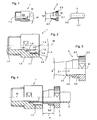
- Fig. 1 is a hose coupling according to the invention consisting of a base body 1 and a closure body 2 shown in an exploded view.
- the hose coupling is rotationally symmetrical to a central axis M.
- the closure body 2 is, as in Fig. 4 and 5 shown in detail, put over an end 3.1 of a line 3 and the line 3 with the end 3.1 inserted in the body 1.
- the line 3 between the two bodies 1, 2 clamped and thus in the direction of the central axis M, ie in the axial direction, set and simultaneously sealed.
- a closed hose coupling with a connected line 3 is shown in Fig. 5f.
- Fig. 2 shows in detail that the main body 1 has a channel 1.1, which passes through the base body 1 in the axial direction to the central axis M.
- a pipe socket 1.5 is formed, which is surrounded by a housing section 1.2, so that the housing section 1.2 and the pipe socket 1.5 form an annular gap 1.3.
- the annular gap 1.3 is formed inwardly in the direction of the cylindrical pipe socket 1.5, which has an aligned in the direction of the closure body 2 muzzle 1.4, via which the conduit 3 is slipped.
- the annular gap 1.3 is formed by a thread formed as an internal thread 1.7 and a subsequent thereto in the axial direction conical surface 1.8.
- the thread 1.7 corresponds to a in Fig. 3 shown thread 2.2 of the closure body. 2
- the base body 1 has a stop face acting in the axial direction 1.6, against which a stop surface 2.5 of the in Fig. 3 shown closure body 2 abuts when closing the hose coupling.
- the closure body 2 is according to Fig. 3 formed from a control panel 2.3 and a subsequent to the control panel 2.3 clamping sleeve 2.4, which can be applied to the line 3. Between the clamping sleeve 2.4 and the control unit 2.3, the thread 2.2 is provided circumferentially on the closure body 2.
- the stop surface 2.5 is shown, with the stop surface 1.6 to the closed state of the hose coupling a in Fig. 4 illustrated gap 4 forms and strikes in the closed state to the stop surface 1.6 visible from the outside.
- the line 3 is continued.
- Fig. 5 is shown as the abutment surface 2.5 of the closure body 2 abuts after screwing the two bodies 1, 2 against the abutment surface 1.6 of the body 1, so that a further screw and an increased clamping action after the gap formed between the two bodies 1, 2 4 closed is, can not be increased.
- the maximum deformation should only take place in a very small area of the line 3, so that preferably a clamping surface which is linear in the circumferential direction is formed. This is achieved by a different inclination of the conical surface 1.8 and a countercone surface 2.6.
- the Jacobkonus description 2.6 is with an inclination angle k of about 6 ° ( Fig. 1 and 3 ) shallower than the cone surface 1.8 with an inclination angle g of about 15 ° ( Fig. 1 and 2 ).
- the clamping sleeve 2.4 is in the circumferential direction of the cone surface on 1.8 and is also pressed linearly against the line 3 when closing the hose coupling.
- Fig. 6 is a view of an embodiment with a viewing direction in the axial direction of the closure body 2 shown, in which the control unit 2.3 and thus the four abutment surfaces 1.6 of the closure body 2 formed of a plurality of sub-bodies, each having a partial surface are arranged as pitch segments about the central axis M.
- the viewing direction is in Fig. 5 illustrated with an arrow.
- a spacer ring 5 is shown, which is positioned in the axial direction between the two stop surfaces 1.6, 2.5 and attached to the closure body 2.
- the spacer ring 5 the necessary clamping effect is achieved earlier when using cables 3 with a larger wall thickness 3.3, so that the gap 4 must be closed earlier.
- a hose coupling is shown, which does not belong to the invention, in which the clamping sleeve 2.4 is formed as a separate component and the base body 1 does not form an annular gap 1.3.
- this applied to smaller diameters of lines 3 hose coupling is based on the same principle, according to which the clamping effect is limited by a stop position of the two stop surfaces 1.6, 2.5 in the axial direction.
- hose coupling can also be formed with an external thread 1.7 on the base body 1 and an internal thread 2.2 on the closure body 2.
- the separate clamping sleeve 2.4 is supported by a bearing ring 2.7 in the radial direction in the closure body 2.
- the linear contact with the line 3 is achieved by the inner surface of the clamping sleeve 2.4, which in relation to the central axis M against the embodiment according to Fig. 1 to 7 not parallel but employed.
- the main body 1 as an external or internal thread and the closure body 2 has a corresponding thread formed as an internal or external thread.
Landscapes
- Engineering & Computer Science (AREA)
- General Engineering & Computer Science (AREA)
- Mechanical Engineering (AREA)
- Health & Medical Sciences (AREA)
- Heart & Thoracic Surgery (AREA)
- Pulmonology (AREA)
- Anesthesiology (AREA)
- Biomedical Technology (AREA)
- Hematology (AREA)
- Life Sciences & Earth Sciences (AREA)
- Animal Behavior & Ethology (AREA)
- General Health & Medical Sciences (AREA)
- Public Health (AREA)
- Veterinary Medicine (AREA)
- Clamps And Clips (AREA)
- Joints That Cut Off Fluids, And Hose Joints (AREA)
Claims (12)
- Raccord pour tuyau en deux parties en matière plastique, composé d'un corps de base (1) et d'un corps de fermeture (2) pour le raccordement étanche d'une conduite de tuyau ou de tube (3), le corps de base (1) présentanta) au moins une gaine (1.1) qui est coaxiale à un axe médian M dans le corps de base (1) et se termine dans une tubulure (1.5) avec une embouchure (1.4) etb) un tronçon de logement (1.2) disposé de façon coaxiale à l'axe médian M autour de la tubulure (1.5) et un interstice annulaire (1.3) formé entre la gaine (1.1) et le tronçon de logement (1.2), disposé de façon coaxiale à l'axe médian M et ouverte vers l'embouchure (1.4) et le corps de fermeture (2)c) un orifice de passage (2.1) disposé de façon coaxiale à l'axe médian M pour le passage d'une conduite (3) etd) une partie de manoeuvre (2.3) réalisée pour le vissage manuel,e) le corps de base (1) et le corps de fermeture (2) présentant chacun au moins une face de butée (1.6, 2.5) agissant dans une direction parallèle par rapport à l'axe médian M, et les deux faces de butée (1.6, 2.5) étant, après le raccordement de la conduite de tuyau ou de tube (3), adjacentes l'une à l'autre dans une position extrême E indirectement ou directement de façon visible de l'extérieur,
caractérisé en ce quef) le corps de fermeture (2) présente un élément de serrage (2.4) qui se raccorde à l'orifice de passage (2.1) dans la direction axiale et qui peut être introduit dans l'interstice annulaire (1.3) pour le raccordement de la conduite (3) et qui peut être posé contre la conduite (3),g) la valeur de la force de serrage de l'élément de serrage réalisé en tant que douille de serrage (2.4) n'est maximale que quand le corps de base (1) et le corps de fermeture (2) se trouve dans la position extrême E, eth) la douille de serrage (2.4) forme une surface de serrage linéaire dans la direction circonférentielle. - Raccord pour tuyau selon la revendication 1, caractérisé en ce que le tronçon de logement (1.2) présente une face de cône (1.8) dont le diamètre s'agrandit en direction de l'embouchure (1.4) et qui est dirigée dans l'interstice annulaire (1.3) et est disposée de façon coaxiale à l'axe médian M, en ce que la douille de serrage (2.4) présente une face de cône complémentaire (2.6) périphérique, un angle k de la face de cône (1.8) étant plus grand qu'un angle g de la face de cône complémentaire (2.6).
- Raccord pour tuyau selon la revendication 2, caractérisé en ce que la profondeur d'enfichage (t) de la douille de serrage (2.4) dans l'interstice annulaire (1.3) est maximale quand le corps de base (1) et le corps de fermeture (2) se trouvent dans la position extrême E.
- Raccord pour tuyau selon une des revendications précédentes, caractérisé en ce que les deux faces de butée (1.6, 2.5) peuvent être directement et réciproquement posées l'une contre l'autre dans la direction axiale.
- Raccord pour tuyau selon une des revendications précédentes, caractérisé en ce que le raccord pour tuyau est réalisé en trois parties ou en plusieurs parties avec une bague d'espacement (5) séparée, et en ce que les deux faces de butée (1.6, 2.5) peuvent être indirectement adjacentes dans la direction axiale par le biais de la bague d'espacement (5).
- Raccord pour tuyau selon une des revendications précédentes, caractérisé en ce que le corps de base (1) et le corps de fermeture (2) présentent respectivement un filet (1.7, 2.2) disposé de façon coaxiale à l'axe médian M, les deux filets (1.7, 2.2) pouvant être assemblés l'un à l'autre par vissage pour le raccordement de la conduite (3).
- Raccord pour tuyau selon la revendication 6, caractérisé en ce que la douille de serrage (2.4) peut être introduite sur une certaine longueur dans la direction axiale dans l'interstice annulaire (1.3) par les deux filets (1.7, 2.2), sur laquelle longueur le corps de base (1) et le corps de fermeture (2) sont fermés par les filets (1.7, 2.2) lors de la rotation de fermeture.
- Raccord pour tuyau selon une des revendications précédentes, caractérisé en ce que la douille de serrage (2.4) est poussée suffisamment loin dans l'interstice annulaire (1.3) pour que la conduite (3) soit déformée par la douille de serrage (2.4) dans la direction radiale sur une certaine longueur comprise entre 4 et 6 % d'une épaisseur de paroi (3.3) initiale.
- Raccord pour tuyau selon une des revendications 6 ou 7, caractérisé en ce qu'un filet (2.2) réalisé en tant que filet extérieur se raccorde dans la direction axiale à la partie de manoeuvre (2.3), et en ce que la douille de serrage (2.4) se raccorde au filet (2.2) dans la direction axiale, et en ce que le filet (1.7) réalisé en tant que filet intérieur est prévu sur le tronçon de logement (1.2), le tronçon de logement (1.2) dépassant de la tubulure (1.5) dans la direction axiale.
- Raccord pour tuyau selon une des revendications précédentes, caractérisé en ce que la partie de manoeuvre (2.3) et la douille de serrage (2.4) sont réalisées d'une seule pièce et avec un même matériau.
- Système composé d'un raccord pour tuyau selon une des revendications précédentes 1 à 10 et d'une conduite (3).
- Procédé de raccordement d'une conduite (3) à un raccord pour tuyau en deux parties en matière plastique selon les revendications 6 et 10, caractérisé par les étapes de procédé suivantes :a) enfilement du corps de fermeture (2) sur la conduite (3) ;b) introduction d'une extrémité (3.1) de la conduite (3) dans l'interstice annulaire (1.3) jusqu'à ce qu'une face frontale (3.2) touche une face de butée (1.30), et simultanément poussée de l'extrémité (3.1) de la conduite (3) sur la tubulure (1.5) ;c) emboitement du corps de fermeture (2) avec la douille de serrage (2.4) dans ou sur le corps de base (1), jusqu'à ce que les deux filets (1.7, 2.2) se touchent ;d) vissage des deux filets jusqu'à ce que les faces de butée (1.6, 2.5) se touchent visiblement ou jusqu'à ce qu'aucun interstice (4) ne puisse plus être distingué entre les faces de butée (1.6, 2.5), la force de serrage de la douille de serrage (2.4) étant augmentée en continu par le vissage jusqu'à la position extrême E.
Applications Claiming Priority (1)
| Application Number | Priority Date | Filing Date | Title |
|---|---|---|---|
| DE102010049380A DE102010049380A1 (de) | 2010-10-26 | 2010-10-26 | Schlauchkupplung |
Publications (2)
| Publication Number | Publication Date |
|---|---|
| EP2447586A1 EP2447586A1 (fr) | 2012-05-02 |
| EP2447586B1 true EP2447586B1 (fr) | 2013-06-19 |
Family
ID=45090909
Family Applications (1)
| Application Number | Title | Priority Date | Filing Date |
|---|---|---|---|
| EP11186778.4A Active EP2447586B1 (fr) | 2010-10-26 | 2011-10-26 | Raccord pour tuyau |
Country Status (4)
| Country | Link |
|---|---|
| EP (1) | EP2447586B1 (fr) |
| DE (1) | DE102010049380A1 (fr) |
| DK (1) | DK2447586T3 (fr) |
| ES (1) | ES2427791T3 (fr) |
Families Citing this family (1)
| Publication number | Priority date | Publication date | Assignee | Title |
|---|---|---|---|---|
| DE102018205397A1 (de) | 2018-04-10 | 2019-10-10 | Wmf Group Gmbh | Klemmring für Schlauchverbindungen, den Klemmring umfassende Klemmvorrichtung für Schlauchverbindungen sowie die Klemmvorrichtung umfassende Schlauchverbindung |
Family Cites Families (8)
| Publication number | Priority date | Publication date | Assignee | Title |
|---|---|---|---|---|
| GB672453A (en) * | 1949-09-15 | 1952-05-21 | Scovill Manufacturing Co | Improvements in pipe couplings |
| US4304422A (en) * | 1980-02-19 | 1981-12-08 | Gould Inc. | Tube coupling with frangible sleeve |
| DE8008838U1 (de) | 1980-03-29 | 1980-07-17 | Em-Technik Gmbh Armaturenbau, 6701 Maxdorf | Schlauchverbinder |
| DE3225172C2 (de) | 1982-07-06 | 1984-04-26 | Gressel AG, 8355 Aadorf, Thurgau | Anschlußnippel für Kunststoffrohre in Steckverbindung |
| DE4211498A1 (de) | 1992-04-06 | 1993-10-07 | Em Technik Gmbh Armaturenbau | Rohrverschraubung für relativ starre Schläuche |
| DE19721179C1 (de) * | 1997-05-21 | 1998-10-08 | Em Technik Gmbh Armaturenbau | Schlauchverschraubung |
| DE102009015640A1 (de) * | 2009-03-23 | 2010-09-30 | Eisele Pneumatics Gmbh & Co. Kg | Vorrichtung zum lösbaren Verbinden mit einem Ende einer röhrenartigen Leitung, insbesondere Schlauch-Schnellverbinder |
| JP4868371B2 (ja) * | 2009-09-02 | 2012-02-01 | 株式会社トヨックス | ホース継手 |
-
2010
- 2010-10-26 DE DE102010049380A patent/DE102010049380A1/de not_active Withdrawn
-
2011
- 2011-10-26 EP EP11186778.4A patent/EP2447586B1/fr active Active
- 2011-10-26 ES ES11186778T patent/ES2427791T3/es active Active
- 2011-10-26 DK DK11186778.4T patent/DK2447586T3/da active
Also Published As
| Publication number | Publication date |
|---|---|
| ES2427791T3 (es) | 2013-11-04 |
| EP2447586A1 (fr) | 2012-05-02 |
| DK2447586T3 (da) | 2013-07-08 |
| DE102010049380A1 (de) | 2012-04-26 |
Similar Documents
| Publication | Publication Date | Title |
|---|---|---|
| DE60205874T2 (de) | Schnellkupplung | |
| EP2233814B1 (fr) | Dispositif de connexion amovible doté d'une extrémité d'une conduite de type tubulaire, notamment connecteur rapide de tuyau | |
| DE2625460C2 (fr) | ||
| DE2731242C2 (de) | Verbindungsanordnung für zwei Rohre mit Blockierung bei Zugbeanspruchung | |
| DE29900796U1 (de) | Vorrichtung zum Verbinden eines Rohrstutzens, rohrförmigen Armaturenteils oder Fittings mit einem Rohr | |
| DE60204287T2 (de) | Kupplung zur verbindung eines rohrs oder schlauchs durch einschieben | |
| EP0327080A1 (fr) | Raccord pour tuyau | |
| DE7717563U1 (de) | Rohrverbindungsstueck | |
| DE60115413T2 (de) | Fitting für eine druckmittelkupplung für kunststoffrohre | |
| DE3923579A1 (de) | Anschlussarmatur fuer rohre, insbesondere fuer kunststoffrohre | |
| DE60020212T2 (de) | Rohrverbindungselement, insbesondere für kunststoffrohre | |
| DE10233862B4 (de) | System zum Verbinden einer röhrenartigen Leitung mit einer Verbindungsvorrichtung, Verfahren zum Bearbeiten eines Endabschnittes der röhrenartigen Leitung und zugehöriges Werkzeug | |
| EP1354163B1 (fr) | Dispositif de raccordement desserrable a une extremite d'un conduite tubulaire, en particulier raccord rapide | |
| EP2447586B1 (fr) | Raccord pour tuyau | |
| EP2008011B1 (fr) | Connecteur pour conduites constituees en particulier de plastique | |
| DE60216087T2 (de) | Vorrichtung zum durchführen einer leitung oder dergleichen durch ein bauelement | |
| DE2230740A1 (de) | Ringdichtung fuer verbindungen an rohrleitungen, armaturen und dergl | |
| EP0306770B1 (fr) | Liaison mécanique pour tuyaux à air comprimé en matière plastique | |
| DE102007017974A1 (de) | Vorrichtung zum Anschließen einer röhrenartigen Leitung, insbesondere einer Schlauchleitung, an ein Anschlussstück | |
| DE69006285T2 (de) | Verbindungsstück für Kunststoffrohre und Montageverfahren. | |
| EP0879377B1 (fr) | Raccord amovible pour tuyaux en plastique | |
| DE69313956T2 (de) | Schlauch mit radialer Spannvorrichtung zum Verbinden mit einem Rohrende; Schlauchverbindung mit diesem Schlauch | |
| DE102010034475B4 (de) | Vorrichtung zum Verbinden mit einem Ende einer röhrenartigen Leitung | |
| DE19811500C2 (de) | Klemmringverbindung | |
| DE10313063A1 (de) | Verbindungselement |
Legal Events
| Date | Code | Title | Description |
|---|---|---|---|
| REG | Reference to a national code |
Ref country code: DE Ref legal event code: R138 Ref document number: 502011000929 Country of ref document: DE Free format text: GERMAN DOCUMENT NUMBER IS 502011000929 Ref country code: DE Ref legal event code: R138 Ref document number: 202011109886 Country of ref document: DE Free format text: GERMAN DOCUMENT NUMBER IS 502011000929 |
|
| PUAI | Public reference made under article 153(3) epc to a published international application that has entered the european phase |
Free format text: ORIGINAL CODE: 0009012 |
|
| AK | Designated contracting states |
Kind code of ref document: A1 Designated state(s): AL AT BE BG CH CY CZ DE DK EE ES FI FR GB GR HR HU IE IS IT LI LT LU LV MC MK MT NL NO PL PT RO RS SE SI SK SM TR |
|
| AX | Request for extension of the european patent |
Extension state: BA ME |
|
| 17P | Request for examination filed |
Effective date: 20120427 |
|
| 17Q | First examination report despatched |
Effective date: 20120731 |
|
| GRAP | Despatch of communication of intention to grant a patent |
Free format text: ORIGINAL CODE: EPIDOSNIGR1 |
|
| GRAP | Despatch of communication of intention to grant a patent |
Free format text: ORIGINAL CODE: EPIDOSNIGR1 |
|
| GRAS | Grant fee paid |
Free format text: ORIGINAL CODE: EPIDOSNIGR3 |
|
| INTG | Intention to grant announced |
Effective date: 20130415 |
|
| GRAA | (expected) grant |
Free format text: ORIGINAL CODE: 0009210 |
|
| AK | Designated contracting states |
Kind code of ref document: B1 Designated state(s): AL AT BE BG CH CY CZ DE DK EE ES FI FR GB GR HR HU IE IS IT LI LT LU LV MC MK MT NL NO PL PT RO RS SE SI SK SM TR |
|
| REG | Reference to a national code |
Ref country code: GB Ref legal event code: FG4D Free format text: NOT ENGLISH |
|
| REG | Reference to a national code |
Ref country code: CH Ref legal event code: EP |
|
| REG | Reference to a national code |
Ref country code: DK Ref legal event code: T3 |
|
| REG | Reference to a national code |
Ref country code: AT Ref legal event code: REF Ref document number: 617859 Country of ref document: AT Kind code of ref document: T Effective date: 20130715 |
|
| REG | Reference to a national code |
Ref country code: SE Ref legal event code: TRGR |
|
| REG | Reference to a national code |
Ref country code: IE Ref legal event code: FG4D Free format text: LANGUAGE OF EP DOCUMENT: GERMAN |
|
| REG | Reference to a national code |
Ref country code: DE Ref legal event code: R096 Ref document number: 502011000929 Country of ref document: DE Effective date: 20130814 |
|
| REG | Reference to a national code |
Ref country code: NL Ref legal event code: T3 |
|
| PG25 | Lapsed in a contracting state [announced via postgrant information from national office to epo] |
Ref country code: GR Free format text: LAPSE BECAUSE OF FAILURE TO SUBMIT A TRANSLATION OF THE DESCRIPTION OR TO PAY THE FEE WITHIN THE PRESCRIBED TIME-LIMIT Effective date: 20130920 Ref country code: NO Free format text: LAPSE BECAUSE OF FAILURE TO SUBMIT A TRANSLATION OF THE DESCRIPTION OR TO PAY THE FEE WITHIN THE PRESCRIBED TIME-LIMIT Effective date: 20130919 Ref country code: FI Free format text: LAPSE BECAUSE OF FAILURE TO SUBMIT A TRANSLATION OF THE DESCRIPTION OR TO PAY THE FEE WITHIN THE PRESCRIBED TIME-LIMIT Effective date: 20130619 Ref country code: LT Free format text: LAPSE BECAUSE OF FAILURE TO SUBMIT A TRANSLATION OF THE DESCRIPTION OR TO PAY THE FEE WITHIN THE PRESCRIBED TIME-LIMIT Effective date: 20130619 Ref country code: SI Free format text: LAPSE BECAUSE OF FAILURE TO SUBMIT A TRANSLATION OF THE DESCRIPTION OR TO PAY THE FEE WITHIN THE PRESCRIBED TIME-LIMIT Effective date: 20130619 |
|
| REG | Reference to a national code |
Ref country code: ES Ref legal event code: FG2A Ref document number: 2427791 Country of ref document: ES Kind code of ref document: T3 Effective date: 20131104 |
|
| REG | Reference to a national code |
Ref country code: LT Ref legal event code: MG4D |
|
| PG25 | Lapsed in a contracting state [announced via postgrant information from national office to epo] |
Ref country code: HR Free format text: LAPSE BECAUSE OF FAILURE TO SUBMIT A TRANSLATION OF THE DESCRIPTION OR TO PAY THE FEE WITHIN THE PRESCRIBED TIME-LIMIT Effective date: 20130619 Ref country code: BG Free format text: LAPSE BECAUSE OF FAILURE TO SUBMIT A TRANSLATION OF THE DESCRIPTION OR TO PAY THE FEE WITHIN THE PRESCRIBED TIME-LIMIT Effective date: 20130919 Ref country code: RS Free format text: LAPSE BECAUSE OF FAILURE TO SUBMIT A TRANSLATION OF THE DESCRIPTION OR TO PAY THE FEE WITHIN THE PRESCRIBED TIME-LIMIT Effective date: 20130619 |
|
| PG25 | Lapsed in a contracting state [announced via postgrant information from national office to epo] |
Ref country code: LV Free format text: LAPSE BECAUSE OF FAILURE TO SUBMIT A TRANSLATION OF THE DESCRIPTION OR TO PAY THE FEE WITHIN THE PRESCRIBED TIME-LIMIT Effective date: 20130619 |
|
| PG25 | Lapsed in a contracting state [announced via postgrant information from national office to epo] |
Ref country code: PT Free format text: LAPSE BECAUSE OF FAILURE TO SUBMIT A TRANSLATION OF THE DESCRIPTION OR TO PAY THE FEE WITHIN THE PRESCRIBED TIME-LIMIT Effective date: 20131021 Ref country code: CZ Free format text: LAPSE BECAUSE OF FAILURE TO SUBMIT A TRANSLATION OF THE DESCRIPTION OR TO PAY THE FEE WITHIN THE PRESCRIBED TIME-LIMIT Effective date: 20130619 Ref country code: CY Free format text: LAPSE BECAUSE OF FAILURE TO SUBMIT A TRANSLATION OF THE DESCRIPTION OR TO PAY THE FEE WITHIN THE PRESCRIBED TIME-LIMIT Effective date: 20130821 Ref country code: EE Free format text: LAPSE BECAUSE OF FAILURE TO SUBMIT A TRANSLATION OF THE DESCRIPTION OR TO PAY THE FEE WITHIN THE PRESCRIBED TIME-LIMIT Effective date: 20130619 Ref country code: SK Free format text: LAPSE BECAUSE OF FAILURE TO SUBMIT A TRANSLATION OF THE DESCRIPTION OR TO PAY THE FEE WITHIN THE PRESCRIBED TIME-LIMIT Effective date: 20130619 Ref country code: IS Free format text: LAPSE BECAUSE OF FAILURE TO SUBMIT A TRANSLATION OF THE DESCRIPTION OR TO PAY THE FEE WITHIN THE PRESCRIBED TIME-LIMIT Effective date: 20131019 |
|
| PG25 | Lapsed in a contracting state [announced via postgrant information from national office to epo] |
Ref country code: RO Free format text: LAPSE BECAUSE OF FAILURE TO SUBMIT A TRANSLATION OF THE DESCRIPTION OR TO PAY THE FEE WITHIN THE PRESCRIBED TIME-LIMIT Effective date: 20130619 Ref country code: PL Free format text: LAPSE BECAUSE OF FAILURE TO SUBMIT A TRANSLATION OF THE DESCRIPTION OR TO PAY THE FEE WITHIN THE PRESCRIBED TIME-LIMIT Effective date: 20130619 |
|
| PG25 | Lapsed in a contracting state [announced via postgrant information from national office to epo] |
Ref country code: CY Free format text: LAPSE BECAUSE OF FAILURE TO SUBMIT A TRANSLATION OF THE DESCRIPTION OR TO PAY THE FEE WITHIN THE PRESCRIBED TIME-LIMIT Effective date: 20130619 |
|
| PLBE | No opposition filed within time limit |
Free format text: ORIGINAL CODE: 0009261 |
|
| STAA | Information on the status of an ep patent application or granted ep patent |
Free format text: STATUS: NO OPPOSITION FILED WITHIN TIME LIMIT |
|
| 26N | No opposition filed |
Effective date: 20140320 |
|
| REG | Reference to a national code |
Ref country code: DE Ref legal event code: R097 Ref document number: 502011000929 Country of ref document: DE Effective date: 20140320 |
|
| PG25 | Lapsed in a contracting state [announced via postgrant information from national office to epo] |
Ref country code: SM Free format text: LAPSE BECAUSE OF FAILURE TO SUBMIT A TRANSLATION OF THE DESCRIPTION OR TO PAY THE FEE WITHIN THE PRESCRIBED TIME-LIMIT Effective date: 20130619 |
|
| PG25 | Lapsed in a contracting state [announced via postgrant information from national office to epo] |
Ref country code: TR Free format text: LAPSE BECAUSE OF FAILURE TO SUBMIT A TRANSLATION OF THE DESCRIPTION OR TO PAY THE FEE WITHIN THE PRESCRIBED TIME-LIMIT Effective date: 20130619 |
|
| PG25 | Lapsed in a contracting state [announced via postgrant information from national office to epo] |
Ref country code: MK Free format text: LAPSE BECAUSE OF FAILURE TO SUBMIT A TRANSLATION OF THE DESCRIPTION OR TO PAY THE FEE WITHIN THE PRESCRIBED TIME-LIMIT Effective date: 20130619 Ref country code: HU Free format text: LAPSE BECAUSE OF FAILURE TO SUBMIT A TRANSLATION OF THE DESCRIPTION OR TO PAY THE FEE WITHIN THE PRESCRIBED TIME-LIMIT; INVALID AB INITIO Effective date: 20111026 |
|
| PG25 | Lapsed in a contracting state [announced via postgrant information from national office to epo] |
Ref country code: MT Free format text: LAPSE BECAUSE OF FAILURE TO SUBMIT A TRANSLATION OF THE DESCRIPTION OR TO PAY THE FEE WITHIN THE PRESCRIBED TIME-LIMIT Effective date: 20130619 |
|
| REG | Reference to a national code |
Ref country code: FR Ref legal event code: PLFP Year of fee payment: 5 |
|
| REG | Reference to a national code |
Ref country code: FR Ref legal event code: PLFP Year of fee payment: 6 |
|
| REG | Reference to a national code |
Ref country code: FR Ref legal event code: PLFP Year of fee payment: 7 |
|
| REG | Reference to a national code |
Ref country code: FR Ref legal event code: PLFP Year of fee payment: 8 |
|
| PG25 | Lapsed in a contracting state [announced via postgrant information from national office to epo] |
Ref country code: AL Free format text: LAPSE BECAUSE OF FAILURE TO SUBMIT A TRANSLATION OF THE DESCRIPTION OR TO PAY THE FEE WITHIN THE PRESCRIBED TIME-LIMIT Effective date: 20130619 |
|
| P01 | Opt-out of the competence of the unified patent court (upc) registered |
Effective date: 20240220 |
|
| REG | Reference to a national code |
Ref country code: CH Ref legal event code: U11 Free format text: ST27 STATUS EVENT CODE: U-0-0-U10-U11 (AS PROVIDED BY THE NATIONAL OFFICE) Effective date: 20251101 |
|
| PGFP | Annual fee paid to national office [announced via postgrant information from national office to epo] |
Ref country code: NL Payment date: 20251021 Year of fee payment: 15 Ref country code: LU Payment date: 20251022 Year of fee payment: 15 |
|
| PGFP | Annual fee paid to national office [announced via postgrant information from national office to epo] |
Ref country code: DE Payment date: 20251021 Year of fee payment: 15 |
|
| PGFP | Annual fee paid to national office [announced via postgrant information from national office to epo] |
Ref country code: GB Payment date: 20251022 Year of fee payment: 15 |
|
| PGFP | Annual fee paid to national office [announced via postgrant information from national office to epo] |
Ref country code: MC Payment date: 20251023 Year of fee payment: 15 |
|
| PGFP | Annual fee paid to national office [announced via postgrant information from national office to epo] |
Ref country code: AT Payment date: 20251022 Year of fee payment: 15 |
|
| PGFP | Annual fee paid to national office [announced via postgrant information from national office to epo] |
Ref country code: DK Payment date: 20251027 Year of fee payment: 15 Ref country code: IT Payment date: 20251022 Year of fee payment: 15 |
|
| PGFP | Annual fee paid to national office [announced via postgrant information from national office to epo] |
Ref country code: FR Payment date: 20251030 Year of fee payment: 15 |
|
| PGFP | Annual fee paid to national office [announced via postgrant information from national office to epo] |
Ref country code: BE Payment date: 20251021 Year of fee payment: 15 |
|
| PGFP | Annual fee paid to national office [announced via postgrant information from national office to epo] |
Ref country code: CH Payment date: 20251101 Year of fee payment: 15 Ref country code: SE Payment date: 20251021 Year of fee payment: 15 |
|
| PGFP | Annual fee paid to national office [announced via postgrant information from national office to epo] |
Ref country code: IE Payment date: 20251024 Year of fee payment: 15 |
|
| PGFP | Annual fee paid to national office [announced via postgrant information from national office to epo] |
Ref country code: ES Payment date: 20251210 Year of fee payment: 15 |