EP2447626A2 - Wärmetauscher, insbesondere zur Anwendung bei Kühlmöbeln - Google Patents
Wärmetauscher, insbesondere zur Anwendung bei Kühlmöbeln Download PDFInfo
- Publication number
- EP2447626A2 EP2447626A2 EP20110008489 EP11008489A EP2447626A2 EP 2447626 A2 EP2447626 A2 EP 2447626A2 EP 20110008489 EP20110008489 EP 20110008489 EP 11008489 A EP11008489 A EP 11008489A EP 2447626 A2 EP2447626 A2 EP 2447626A2
- Authority
- EP
- European Patent Office
- Prior art keywords
- profile
- heat exchanger
- base
- exchanger according
- sections
- Prior art date
- Legal status (The legal status is an assumption and is not a legal conclusion. Google has not performed a legal analysis and makes no representation as to the accuracy of the status listed.)
- Granted
Links
- 239000003507 refrigerant Substances 0.000 claims abstract description 41
- 239000012530 fluid Substances 0.000 claims abstract description 4
- 229910000838 Al alloy Inorganic materials 0.000 claims description 7
- 239000002131 composite material Substances 0.000 claims description 7
- 238000005192 partition Methods 0.000 claims description 6
- 229910052782 aluminium Inorganic materials 0.000 claims description 5
- XAGFODPZIPBFFR-UHFFFAOYSA-N aluminium Chemical compound [Al] XAGFODPZIPBFFR-UHFFFAOYSA-N 0.000 claims description 5
- WYTGDNHDOZPMIW-RCBQFDQVSA-N alstonine Natural products C1=CC2=C3C=CC=CC3=NC2=C2N1C[C@H]1[C@H](C)OC=C(C(=O)OC)[C@H]1C2 WYTGDNHDOZPMIW-RCBQFDQVSA-N 0.000 claims description 4
- 229910052751 metal Inorganic materials 0.000 claims description 4
- 239000002184 metal Substances 0.000 claims description 4
- 150000001875 compounds Chemical class 0.000 claims description 3
- 230000000844 anti-bacterial effect Effects 0.000 claims description 2
- 239000003899 bactericide agent Substances 0.000 claims description 2
- 230000000855 fungicidal effect Effects 0.000 claims description 2
- 239000000417 fungicide Substances 0.000 claims description 2
- 239000001273 butane Substances 0.000 abstract description 2
- IJDNQMDRQITEOD-UHFFFAOYSA-N n-butane Chemical compound CCCC IJDNQMDRQITEOD-UHFFFAOYSA-N 0.000 abstract description 2
- OFBQJSOFQDEBGM-UHFFFAOYSA-N n-pentane Natural products CCCCC OFBQJSOFQDEBGM-UHFFFAOYSA-N 0.000 abstract description 2
- 239000003795 chemical substances by application Substances 0.000 abstract 2
- 239000003570 air Substances 0.000 description 7
- 230000032258 transport Effects 0.000 description 7
- 229910000679 solder Inorganic materials 0.000 description 6
- 238000001125 extrusion Methods 0.000 description 5
- 238000000034 method Methods 0.000 description 5
- 229910045601 alloy Inorganic materials 0.000 description 4
- 239000000956 alloy Substances 0.000 description 4
- 238000005219 brazing Methods 0.000 description 4
- 239000011248 coating agent Substances 0.000 description 4
- 238000000576 coating method Methods 0.000 description 4
- 230000008569 process Effects 0.000 description 4
- 239000012080 ambient air Substances 0.000 description 3
- 230000008901 benefit Effects 0.000 description 3
- 239000000463 material Substances 0.000 description 3
- 238000005057 refrigeration Methods 0.000 description 3
- CURLTUGMZLYLDI-UHFFFAOYSA-N Carbon dioxide Chemical compound O=C=O CURLTUGMZLYLDI-UHFFFAOYSA-N 0.000 description 2
- IHQKEDIOMGYHEB-UHFFFAOYSA-M sodium dimethylarsinate Chemical class [Na+].C[As](C)([O-])=O IHQKEDIOMGYHEB-UHFFFAOYSA-M 0.000 description 2
- HCHKCACWOHOZIP-UHFFFAOYSA-N Zinc Chemical compound [Zn] HCHKCACWOHOZIP-UHFFFAOYSA-N 0.000 description 1
- 229910002092 carbon dioxide Inorganic materials 0.000 description 1
- 239000001569 carbon dioxide Substances 0.000 description 1
- 230000008859 change Effects 0.000 description 1
- 238000010276 construction Methods 0.000 description 1
- 238000005260 corrosion Methods 0.000 description 1
- 230000007797 corrosion Effects 0.000 description 1
- 230000001419 dependent effect Effects 0.000 description 1
- 238000005265 energy consumption Methods 0.000 description 1
- 238000010438 heat treatment Methods 0.000 description 1
- 230000006872 improvement Effects 0.000 description 1
- 238000004519 manufacturing process Methods 0.000 description 1
- 230000009467 reduction Effects 0.000 description 1
- 230000000717 retained effect Effects 0.000 description 1
- 229910052725 zinc Inorganic materials 0.000 description 1
- 239000011701 zinc Substances 0.000 description 1
Images


Classifications
-
- F—MECHANICAL ENGINEERING; LIGHTING; HEATING; WEAPONS; BLASTING
- F25—REFRIGERATION OR COOLING; COMBINED HEATING AND REFRIGERATION SYSTEMS; HEAT PUMP SYSTEMS; MANUFACTURE OR STORAGE OF ICE; LIQUEFACTION SOLIDIFICATION OF GASES
- F25B—REFRIGERATION MACHINES, PLANTS OR SYSTEMS; COMBINED HEATING AND REFRIGERATION SYSTEMS; HEAT PUMP SYSTEMS
- F25B39/00—Evaporators; Condensers
-
- F—MECHANICAL ENGINEERING; LIGHTING; HEATING; WEAPONS; BLASTING
- F28—HEAT EXCHANGE IN GENERAL
- F28D—HEAT-EXCHANGE APPARATUS, NOT PROVIDED FOR IN ANOTHER SUBCLASS, IN WHICH THE HEAT-EXCHANGE MEDIA DO NOT COME INTO DIRECT CONTACT
- F28D1/00—Heat-exchange apparatus having stationary conduit assemblies for one heat-exchange medium only, the media being in contact with different sides of the conduit wall, in which the other heat-exchange medium is a large body of fluid, e.g. domestic or motor car radiators
- F28D1/02—Heat-exchange apparatus having stationary conduit assemblies for one heat-exchange medium only, the media being in contact with different sides of the conduit wall, in which the other heat-exchange medium is a large body of fluid, e.g. domestic or motor car radiators with heat-exchange conduits immersed in the body of fluid
- F28D1/04—Heat-exchange apparatus having stationary conduit assemblies for one heat-exchange medium only, the media being in contact with different sides of the conduit wall, in which the other heat-exchange medium is a large body of fluid, e.g. domestic or motor car radiators with heat-exchange conduits immersed in the body of fluid with tubular conduits
- F28D1/047—Heat-exchange apparatus having stationary conduit assemblies for one heat-exchange medium only, the media being in contact with different sides of the conduit wall, in which the other heat-exchange medium is a large body of fluid, e.g. domestic or motor car radiators with heat-exchange conduits immersed in the body of fluid with tubular conduits the conduits being bent, e.g. in a serpentine or zig-zag
- F28D1/0472—Heat-exchange apparatus having stationary conduit assemblies for one heat-exchange medium only, the media being in contact with different sides of the conduit wall, in which the other heat-exchange medium is a large body of fluid, e.g. domestic or motor car radiators with heat-exchange conduits immersed in the body of fluid with tubular conduits the conduits being bent, e.g. in a serpentine or zig-zag the conduits being helically or spirally coiled
- F28D1/0473—Heat-exchange apparatus having stationary conduit assemblies for one heat-exchange medium only, the media being in contact with different sides of the conduit wall, in which the other heat-exchange medium is a large body of fluid, e.g. domestic or motor car radiators with heat-exchange conduits immersed in the body of fluid with tubular conduits the conduits being bent, e.g. in a serpentine or zig-zag the conduits being helically or spirally coiled the conduits having a non-circular cross-section
-
- F—MECHANICAL ENGINEERING; LIGHTING; HEATING; WEAPONS; BLASTING
- F28—HEAT EXCHANGE IN GENERAL
- F28D—HEAT-EXCHANGE APPARATUS, NOT PROVIDED FOR IN ANOTHER SUBCLASS, IN WHICH THE HEAT-EXCHANGE MEDIA DO NOT COME INTO DIRECT CONTACT
- F28D1/00—Heat-exchange apparatus having stationary conduit assemblies for one heat-exchange medium only, the media being in contact with different sides of the conduit wall, in which the other heat-exchange medium is a large body of fluid, e.g. domestic or motor car radiators
- F28D1/02—Heat-exchange apparatus having stationary conduit assemblies for one heat-exchange medium only, the media being in contact with different sides of the conduit wall, in which the other heat-exchange medium is a large body of fluid, e.g. domestic or motor car radiators with heat-exchange conduits immersed in the body of fluid
- F28D1/04—Heat-exchange apparatus having stationary conduit assemblies for one heat-exchange medium only, the media being in contact with different sides of the conduit wall, in which the other heat-exchange medium is a large body of fluid, e.g. domestic or motor car radiators with heat-exchange conduits immersed in the body of fluid with tubular conduits
- F28D1/047—Heat-exchange apparatus having stationary conduit assemblies for one heat-exchange medium only, the media being in contact with different sides of the conduit wall, in which the other heat-exchange medium is a large body of fluid, e.g. domestic or motor car radiators with heat-exchange conduits immersed in the body of fluid with tubular conduits the conduits being bent, e.g. in a serpentine or zig-zag
- F28D1/0477—Heat-exchange apparatus having stationary conduit assemblies for one heat-exchange medium only, the media being in contact with different sides of the conduit wall, in which the other heat-exchange medium is a large body of fluid, e.g. domestic or motor car radiators with heat-exchange conduits immersed in the body of fluid with tubular conduits the conduits being bent, e.g. in a serpentine or zig-zag the conduits being bent in a serpentine or zig-zag
- F28D1/0478—Heat-exchange apparatus having stationary conduit assemblies for one heat-exchange medium only, the media being in contact with different sides of the conduit wall, in which the other heat-exchange medium is a large body of fluid, e.g. domestic or motor car radiators with heat-exchange conduits immersed in the body of fluid with tubular conduits the conduits being bent, e.g. in a serpentine or zig-zag the conduits being bent in a serpentine or zig-zag the conduits having a non-circular cross-section
-
- F—MECHANICAL ENGINEERING; LIGHTING; HEATING; WEAPONS; BLASTING
- F28—HEAT EXCHANGE IN GENERAL
- F28F—DETAILS OF HEAT-EXCHANGE AND HEAT-TRANSFER APPARATUS, OF GENERAL APPLICATION
- F28F1/00—Tubular elements; Assemblies of tubular elements
- F28F1/02—Tubular elements of cross-section which is non-circular
- F28F1/022—Tubular elements of cross-section which is non-circular with multiple channels
-
- F—MECHANICAL ENGINEERING; LIGHTING; HEATING; WEAPONS; BLASTING
- F28—HEAT EXCHANGE IN GENERAL
- F28F—DETAILS OF HEAT-EXCHANGE AND HEAT-TRANSFER APPARATUS, OF GENERAL APPLICATION
- F28F1/00—Tubular elements; Assemblies of tubular elements
- F28F1/02—Tubular elements of cross-section which is non-circular
- F28F1/025—Tubular elements of cross-section which is non-circular with variable shape, e.g. with modified tube ends, with different geometrical features
-
- F—MECHANICAL ENGINEERING; LIGHTING; HEATING; WEAPONS; BLASTING
- F28—HEAT EXCHANGE IN GENERAL
- F28F—DETAILS OF HEAT-EXCHANGE AND HEAT-TRANSFER APPARATUS, OF GENERAL APPLICATION
- F28F2265/00—Safety or protection arrangements; Arrangements for preventing malfunction
- F28F2265/20—Safety or protection arrangements; Arrangements for preventing malfunction for preventing development of microorganisms
Definitions
- the invention relates to a heat exchanger having a base profile made of metal, which is connected at its one end to an inlet device and at its other end to an outlet device for a refrigerant.
- a heat exchanger is used in particular for use in refrigerated cabinets, such as refrigerators, freezers, refrigerators and freezers.
- Known heat exchanger devices for refrigeration cabinets typically have a serpentine curved conduit between an inlet for a refrigerant and the outlet for the refrigerant.
- Such pipelines have a circular cross-section hollow chamber and a comparatively small heat exchange surface for the heat exchange. This is expressed in a large hydraulic diameter.
- large pipe lengths are necessary, which are associated with significant pressure losses between the inlet device and the outlet device for the refrigerant. This requires appropriately sized compressors, which increases energy consumption.
- a comparatively long refrigerant pipe is required, or there are provided means for increasing the heat exchange, as known for example from heat exchangers for use in motor vehicle air conditioners, namely fins, which are arranged between the multi-chamber hollow profiles and at Multi-chamber hollow profiles made of aluminum material are connected via a brazed joint.
- fins which are arranged between the multi-chamber hollow profiles and at Multi-chamber hollow profiles made of aluminum material are connected via a brazed joint.
- Such fins increase the heat exchange surface, but make the heat exchanger more expensive by the necessary solder connection.
- Object of the present invention is to provide a heat exchanger, in particular for use in refrigerated furniture, available, which has a high heat exchange performance and is easy to produce.
- the base profile made of metal, preferably of aluminum or an aluminum alloy, is present as the refrigerant line, which is arranged between an inlet device and an outlet device and connected to the respective devices.
- the base profile may be a serpentine, serpentine or meandering conduit for the refrigerant between the inlet means and the outlet means, ie, starting from the inlet means Basic profile a first profile section where the refrigerant is transported in the main flow direction. At a reversal point, the refrigerant line is bent and the flow direction is changed.
- the refrigerant is transported further in a further second profile section counter to the main flow direction in order to be conducted again in the opposite direction, namely in the main flow direction, at the next reversal point. This is repeated until the refrigerant reaches the outlet.
- the refrigerant line formed by the base profile thus comprises first profile sections for flow of the refrigerant in the main flow direction and second profile sections for flow of the refrigerant against the main flow and between the first and second profile sections curved profile sections at the reversal points of the flow direction. This is comparable to prior art devices.
- In the heat exchanger according to the invention are also means for increasing the heat exchange with the surrounding air or with an additionally provided flowing in the cross-flow fluid, preferably a cooled air flow provided.
- Such deformations may be Verwellept of the profile, so that the profile of a reversal point to the opposite reversal point takes a wavy, preferably sinusoidal course.
- the profile is formed around an axis extending in the main flow or countercurrent axis, ie is twisted, so that a spiral course results.
- Another possible deformation of the base profile is a twist, i. a rotation in the longitudinal axis of the profile.
- the basic profile is preferably an extruded flat multi-chamber hollow profile with two parallel broad sides and two arched narrow sides.
- the extruded multi-chamber hollow profiles used have in cross-section a width between 5 mm and 32 mm, a height between 0.6 mm and 3 mm and a wall thickness between 0.1 mm and 0.5 mm.
- the number of chambers in such a multi-chamber hollow profile is between 0.5 chambers / mm width of the basic profile to 2 chambers / mm width of the base profile.
- the chambers of such a basic profile can, as in known multi-chamber hollow sections used for heat exchangers, have round, oval or polygonal cross sections.
- multi-chamber hollow profile strand After extrusion and a possible desired coating of multi-chamber hollow profile strand is deformed, for example verwellt, twisted or twisted. This can be done, for example, sections of the profile strand, ie, provided for the heat exchanger first and second profile sections are formed and then bent at intended reversal points so that each subsequent profile sections come to lie next to each other or with each other. In the forming process, the chambers of the multi-chamber hollow profile are retained.
- a preferred embodiment of a heat exchanger for refrigeration cabinets has profile sections of the basic profile with sinusoidal corrugations, i. the multi-chamber hollow profiles are bent by a forming process.
- the forming force presses from the top and bottom against the broad sides of the multi-chamber hollow profiles, so that there are sinusoidal Verwellept the profile sections with elevations and depressions.
- the individual elevations and depressions can be generated successively on a profile section or simultaneously, depending on the forming device used.
- a corrugated profile section in the main flow direction is subsequently also curved by a profile section which transports the refrigerant counter to the main flow direction, then it is preferred for elevations and depressions of the aforementioned profile sections to be provided in such a way that in the heat exchanger in each case an elevation of a first Profile section adjacent to a recess of a second profile section lies. In this way, a particularly good heat exchange performance, for example achieved with the ambient air or a cross-flow airflow.
- a compact heat exchanger can also be produced by using a plurality of base profiles, each basic profile having deformed first and second profile sections, ie corrugated, twisted or twisted profile sections.
- Each individual basic profile has a refrigerant line that lies in one plane and, as it were, results in one layer.
- Several basic profiles in the heat exchanger then mean several layers, each basic profile is preferably connected to the same inlet and outlet device.
- Such an inlet or outlet device may preferably be an extruded profile piece of aluminum material, which has corresponding recesses corresponding to the number of basic profiles provided in the heat exchanger.
- a connection of the ends of the base profiles with the inlet or outlet device can be made in a simple manner by flame brazing, but also by other known connection options.
- the aforementioned multiple layers in the heat exchanger are preferably separated from one another by separating plates as in known applications in refrigerated cabinets.
- Such partition plates may be made of plastic or of an aluminum alloy.
- the partition plate may be a plastic plate, a smooth sheet or punched perforated plate, a grid or an expanded metal parting plate.
- the connection of the base profiles with the partition plates is effected by a positive and / or non-positive and / or material connection, in the simplest way by a mechanical clamping. There are also solder joints possible.
- heat exchanger according to the invention, however, is that by the deformations in the simplest way, clamping is possible and can be dispensed with a solder joint and thus a relatively expensive process step. If heat exchangers have a plurality of basic profiles, ie several layers of deformed basic profiles arranged one above the other, then the overall height of the deformed basic profile is selected to be between 3 mm and 50 mm.
- the advantage of the heat exchanger according to the invention is that it has a very small hydraulic diameter. Because of this, less refrigerant is needed.
- the refrigerators can use smaller compressors that are quieter and require less energy.
- Another advantage is the material-uniform simple construction, consisting of extruded base profiles and optionally extruded inlet devices and outlet devices, which could be connected to one another in a simple manner by flame brazing. An expensive solder coating for a braze joint, such as for the connection of fins and multi-chamber hollow profiles known from the prior art, is not necessary for the basic profiles.
- the choice of aluminum alloy namely 1XXX, 3XXX, 5XXX, 6XXX alloys, in particular A1MgSi or A1Mg alloys, depends on the desired strength and corrosion resistance of the heat exchanger, ie on its intended use.
- the heat exchanger according to the invention can also be used advantageously for other applications than for refrigerated cabinets.
- heat exchange projecting ribs may be provided on the outer surfaces of the base profile, as in multi-chamber hollow sections for automotive heat exchangers. Another possibility is dependent on the configuration of the deformation at the first and second profile sections. Thus, if gaps between the first and second profile sections are present, inserted into these spaces in addition turbulators.
- the Fig.1 shows a heat exchanger according to the invention for use in refrigerated cabinets.
- This comprises two basic profiles, namely the basic profile 10 and the base profile 10 '. Both basic profiles 10, 10 'are connected at one end 11 to an inlet device 21 and at the other end 12 to an outlet device 22 for a refrigerant. Butane or carbon dioxide is used in particular as refrigerant for refrigerated cabinets.
- the inlet device 21 and the outlet device 22 are extruded profile pieces made of an aluminum alloy, in particular an A1Mg alloy.
- the inlet device 21 and the outlet device 22 each have two recesses whose cross section is adapted to the ends 11 and 12 of the base profiles 10, 10 ', which are inserted into the inlet device 21 and into the outlet device 22 and are connected by flame brazing with these.
- the basic profiles 10, 10 are extruded multi-chamber hollow profiles made from an AlMgSi alloy.
- the extruded multi-chamber hollow profile strands were verwellt in a deformation process.
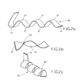
- a portion of such a basic profile 10 with Verwellept 30 is in the 2a shown.
- the base profile 10 is a multi-chamber hollow profile with a plurality of chambers 19, which increase the wettable inner surface for the refrigerant.
- the Verwellepteptept 30 lead to a sinusoidal profile of the base profile 10 with elevations 31 and recesses 32. As better Fig.
- the base profile 10, 10 ' has different profile sections, namely profile sections which connect the base profile with the inlet device 21 and the outlet device 22 and profile sections 13 which transport the refrigerant in the main flow direction 60 to a reversal point 17, where the base profile 10, 10 'is bent over to a profile section 15 and the subsequent profile section 14 transports the refrigerant in a direction opposite to the main flow direction 60.
- This profile section 14 has Verwellept 30.
- the Verwellepteptept 30 end in the area of the reversal point 18, where the curved profile section 16 is located.
- the profile sections 15, 16 are bent so that the first profile sections 13 and the second profile sections 14 are arranged side by side.
- a separating plate 80 is provided between the one layer with the deformed base profile 10 and the other layer with the deformed base profile 10 ', in this case an aluminum sheet.
- the connection between the base profiles 10, 10 'and the separating plate 80 is effected by a clamping, which is not shown in this example.
- the partition plate 80 may additionally have perforations, punched out. This reduces the weight of the heat exchanger and leads to additional turbulence of the transverse air flow.
- heating wires can be arranged for a de-icing. For smaller heat exchangers can be dispensed with the separating plate, since by the deformation 30 of the basic profiles 10, 10 'are relatively stable units.
- a coating can, similar to a known solder or zinc coating, take place after the extrusion of the multi-chamber hollow profiles.
- Such a deformation is preferably carried out for the first profile section 13 in the main flow direction 60 and second profile sections 14 in the counterflow direction. At the reversal points 17, 18 bent profile sections 15, 16 are provided.
- all basic profiles 10, 10 ', 10 “changed by the deformation of Cross-section of the profile, ie, despite the deformations, there are no restrictions or other cross-sectional reductions, which could lead to pressure losses of the refrigerant.
- the basic profiles 10, 10 ', 10 "have a small hydraulic diameter and a good heat exchange performance with the ambient air or a cross-flowed fluid, without additional fins are provided.
- a further advantageous embodiment of a heat exchanger according to the invention shows Figure 3 ,
- a heat exchanger is schematically shown, which consists of a base profile 10 which is connected at one end 11 with an inlet device 21 and at the other end 12 with an outlet device 22.
- the base profile 10 is also a multi-chamber hollow profile, but composite profile.
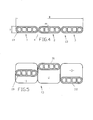
- the basic profile 10 is in cross section in Figure 4 shown. It consists of three strands 1, 2, 3, which are connected to each other via a compound 4.
- the composite sites 4 extend in the longitudinal direction of the composite profile in each case between the strands 1 and 2 or 2 and 3 or other strands.
- the composite profile has a width B of 18 mm, a height H of 1.7 mm and a wall thickness D of 0.35 mm.
- Each strand 1, 2, 3 has four chambers 19.
- the width of these chambers is 1.05 mm
- the wall thickness of the compound 4 is 0.1 mm.
- width B of the base profile 10 after extrusion between 5 mm and 32 mm
- height H of the base profile 10 between 0.6 mm and 3 mm
- the wall thickness D of the base profile 10 between 0.1 mm and 0 , 5 mm.
- widths B of the basic profile 10 are provided between 0.5 and 2 chambers per millimeter.
- the in Figure 4 shown cross-section corresponds to the cross section of the base profile 10 in the heat exchanger in the region of the ends 11, 12 and in the region of the reversal points 17, 18, ie the curved profile sections 15 in the region of the reversal point 17 and the curved profile sections 16 in the region of the reversal point 18.
- a corrugated profile section 13 in which the refrigerant is transported substantially in the main flow direction 60.
- Verwelleptepteptept 30 and the profile section 13 goes into the profile section 15 via.
- the composite profile is bent over to subsequently transport the refrigerant in the profile section 14 counter to the main flow direction 60 back to the reversal point 18.
- the profile section 14 has comparable Verwellache 30 as the profile section 13, which is above and below then again below the profile section 14. At the reversal point 18 follows the curved profile section 16, where the flow direction is changed again.
- This profile section 16 has, comparable to the profile section 15, no Verwellept.
- the first profile sections 13, which transport the refrigerant in the main flow direction 60 repeat the profile sections 15 which reverse the flow direction of the refrigerant by a deflection of the base profile 10, so that in second profile sections 14 the refrigerant is opposite to the main flow direction 60 is passed to the other side of the heat exchanger to change there again in a profile section 16, the flow direction.
- the strands 1, 2, 3 Over a substantial part of its longitudinal extent of the profile section 13 and profile section 14 is deformed.
- the strands 1, 2, 3 still connected after extrusion are separated from one another in the region of the very thin composite sites 4.
- the warps 30 are different in this example for the strands 1, 2 and 3.
- the strand 1 extends from the end 11 initially undeformed, the strand 2 is curved by a forming force up to an increase 31 and the extruded profile 3 by forming force from top to bottom bent to a recess 32.
- a cross section is best Figure 5 to see where the profile section 13 is shown, in the same way it could also be a grooved profile section 14. It becomes clear that these are separate strands 1, 2, 3.
- the strands 1, 2, 3 have comparable waveforms in terms of amplitude and wavelength, but the waveforms are offset from each other, namely as out Figure 3 can be seen, the Verwellept 30 are such that the staggered wave crests and troughs of the three corrugated strands 1, 2, 3 of the profile sections 13, 14 of the give a basic profile 10 as good as possible turbulence of a cross-flow air stream, comparable to turbulence in heat exchangers of the prior art consisting of multi-chamber hollow sections with soldered lamellae.
- the configured as a multi-chamber hollow profile base profile 10 thus takes on two tasks, it is namely refrigerant pipe and slat at the same time.
- the production of such a heat exchanger is relatively inexpensive, as can be dispensed with a Lotbe slaughterung in the multi-chamber hollow sections and a brazing between lamellae and the refrigerant leading multi-chamber hollow sections.
Landscapes
- Engineering & Computer Science (AREA)
- Physics & Mathematics (AREA)
- Thermal Sciences (AREA)
- Mechanical Engineering (AREA)
- General Engineering & Computer Science (AREA)
- Geometry (AREA)
- Heat-Exchange Devices With Radiators And Conduit Assemblies (AREA)
Abstract
Description
- Die Erfindung betrifft einen Wärmetauscher mit einem Grundprofil aus Metall, welches an seinem einen Ende mit einer Einlasseinrichtung und an seinem anderen Ende mit einer Auslasseinrichtung für ein Kältemittel verbunden ist. Ein solcher Wärmetauscher dient insbesondere zur Anwendung bei Kühlmöbeln, wie beispielsweise Kühlschränken, Gefrierschränken, Kühl- und Gefrierkombinationen.
- Bekannte Wärmetauschervorrichtungen für Kühlmöbel besitzen in der Regel eine schlangenförmig gebogene Rohrleitung zwischen einem Einlass für ein Kältemittel und dem Auslass für das Kältemittel. Derartige Rohrleitungen besitzen eine im Querschnitt kreisförmige Hohlkammer und für den Wärmeaustausch eine vergleichsweise kleine Wärmeaustauschoberfläche. Dies drückt sich in einem großen hydraulischen Durchmesser aus. Für die geforderte Wärmeaustauschleistung sind große Rohrlängen notwendig, die mit erheblichen Druckverlusten zwischen der Einlasseinrichtung und der Auslasseinrichtung für das Kältemittel verbunden sind. Dies macht entsprechend dimensionierte Kompressoren notwendig, wodurch der Energieverbrauch steigt.
- Eine Verbesserung wird durch die Verwendung von Mehrkammerhohlprofilen als Grundprofil für die Kältemittelleitung erzielt. In der deutschen Offenlegungsschrift
DE 10 2007 023 696 A1 besteht eine solche Kältemittelleitung aus einem schlangenförmig geformten Mehrkammerhohlprofil. Aufgrund der entsprechenden Anzahl von Kammern vergrößert sich die benetzbare Innenoberfläche, wodurch sich der hydraulische Durchmesser einer solchen Kältemittelleitung verringert. Der hydraulische Durchmesser (Dh = 4A / U) ist der Quotient aus dem vierfachen Strömungsquerschnitt und dem vom Kältemittel benetzten Umfang. Je kleiner der Wert für den hydraulischen Durchmesser ist, um so energieeffizie ter ist der Wärmetauscher. Um eine ausreichend Temperaturdifferenz durch einen solchen Wärmetauscher zu erzielen, ist eine vergleichsweise lange Kältemittelleitung nötig, oder es werden Mittel zur Erhöhung des Wärmeaustausches vorgesehen, wie sie beispielsweise von Wärmetauschern zur Verwendung in Kraftfahrzeugklimaanlagen bekannt sind, nämlich Lamellen, die zwischen den Mehrkammerhohlprofilen angeordnet und bei Mehrkammerhohlprofilen aus Aluminiummaterial über einen Hartlotverbindung verbunden werden. Solche Lamellen erhöhen die Wärmeaustauschoberfläche, verteuern jedoch den Wärmetauscher durch die notwendige Lotverbindung. - Aufgabe der vorliegenden Erfindung ist es, einen Wärmetauscher, insbesondere zur Anwendung bei Kühlmöbeln, zur Verfügung zu stellen, der eine hohe Wärmeaustauschleistung besitzt und einfach herstellbar ist.
- Diese Aufgabe wird mit einem Wärmetauscher mit den Merkmalen des Anspruches 1 gelöst. Bei dem neuen erfindungsgemäßen Wärmeaustauscher ist mindestens ein Grundprofil aus Metall, vorzugsweise aus Aluminium oder einer Aluminiumlegierung, als Kältemittelleitung vorhanden, die zwischen einer Einlasseinrichtung und einer Auslasseinrichtung angeordnet und mit den jeweiligen Einrichtungen verbunden ist. In bekannter Weise kann das Grundprofil eine schlangenförmige, serpentinenförmige oder mäanderförmige Leitung für das Kältemittel zwischen der Einlasseinrichtung und der Auslasseinrichtung sein, d.h. ausgehend von der Einlasseinrichtung besitzt das Grundprofil einen ersten Profilabschnitt, wo das Kältemittel in Hauptströmrichtung transportiert wird. An einer Umkehrstelle wird die Kältemittelleitung gebogen und die Strömungsrichtung geändert. Das Kältemittel wird entgegen der Hauptströmrichtung in einem weiteren zweiten Profilabschnitt weitertransportiert, um an der nächsten Umkehrstelle wieder in die Gegenrichtung, nämlich in die Hauptströmrichtung geleitet zu werden. Dies wiederholt sich, bis das Kältemittel die Auslasseinrichtung erreicht. Die durch das Grundprofil gebildete Kältemittelleitung umfasst somit erste Profilabschnitte zum Durchfluss des Kältemittels in Hauptströmrichtung sowie zweite Profilabschnitte zum Durchfluss des Kältemittels entgegen der Hauptströmrichtung sowie zwischen den ersten und zweiten Profilabschnitten gebogene Profilabschnitte an den Umkehrstellen der Strömungsrichtung. Dies ist vergleichbar zu Vorrichtungen des Standes der Technik. Bei dem erfindungsgemäßen Wärmetauscher sind ebenfalls Mittel zur Erhöhung des Wärmeaustauschs mit der umgebenden Luft oder mit einem zusätzlich vorgesehenen im Querstrom fließenden Fluid, vorzugsweise ein gekühlter Luftstrom, vorgesehen. Hierbei handelt es sich jedoch nicht um die bekannten Lamellen, die über eine Lotverbindung mit dem Grundprofil verbunden werden müssen, sondern das Grundprofil ist zur Erhöhung des Wärmeaustausches selbst verformt und zwar die ersten und zweiten Profilabschnitte. Diese Profilabschnitte sind quer zur Hauptströmrichtung mehrfach verformt.
- Solche Verformungen können Verwellungen des Profils sein, sodass das Profil von einer Umkehrstelle zur gegenüberliegenden Umkehrstelle einen wellenförmigen, vorzugsweise sinusförmigen, Verlauf nimmt. Eine weitere Möglichkeit besteht darin, dass das Profil um eine in Hauptströmrichtung bzw. Gegenströmrichtung verlaufende Achse herum geformt ist, also verdreht ist, so dass sich ein spiralförmiger Verlauf ergibt. Eine weitere mögliche Verformung des Grundprofils stellt eine Verdrillung dar, d.h. eine Verdrehung in Längsachse des Profils.
- Bei dem Grundprofil handelt es sich vorzugsweise um ein stranggepresstes flaches Mehrkammerhohlprofil mit zwei parallelen Breitseiten und zwei gewölbten Schmalseiten. Die verwendeten stranggepressten Mehrkammerhohlprofile besitzen im Querschnitt eine Breite zwischen 5 mm und 32 mm, eine Höhe zwischen 0,6 mm und 3 mm und eine Wanddicke zwischen 0,1 mm und 0,5 mm. Die Anzahl der Kammern in einem solchen Mehrkammerhohlprofil liegt zwischen 0,5 Kammern/mm Breite des Grundprofils bis 2 Kammern/mm Breite des Grundprofils. Die Kammern eines solchen Grundprofils können, wie bei bekannten für Wärmetauscher verwendeten Mehrkammerhohlprofilen runde, ovale oder mehreckige Querschnitte besitzen. Nach dem Strangpressen und einer eventuellen gewünschten Beschichtung wird der Mehrkammerhohlprofilstrang verformt, beispielsweise verwellt, verdreht oder verdrillt. Dies kann beispielsweise abschnittsweise am Profilstrang erfolgen, d.h. die für den Wärmetauscher vorgesehenen ersten und zweiten Profilabschnitte werden geformt und anschließend an vorgesehenen Umkehrstellen so gebogen, dass jeweils nachfolgende Profilabschnitte nebeneinander oder untereinander zu liegen kommen. Bei dem Umformvorgang bleiben die Kammern des Mehrkammerhohlprofils erhalten.
- Eine bevorzugte Ausführungsform eines Wärmetauschers für Kühlmöbel besitzt Profilabschnitte des Grundprofils mit sinusförmigen Verwellungen, d.h. die Mehrkammerhohlprofile sind durch einen Umformvorgang verbogen. Die Umformkraft drückt dabei von oben und unten gegen die Breitseiten der Mehrkammerhohlprofile, so dass sich sinusförmigen Verwellungen der Profilabschnitte mit Erhöhungen und Vertiefungen ergeben. Die einzelnen Erhöhungen und Vertiefungen können nacheinander an einem Profilabschnitt erzeugt werden oder gleichzeitig, abhängig von der verwendeten Umformvorrichtung.
- Wird ein verwellter Profilabschnitt in Hauptströmrichtung nachfolgend von einem Profilabschnitt, welcher das Kältemittel entgegen der Hauptströmrichtung transportiert ebenfalls verwellt, so ist es bevorzugt, dass Erhöhungen und Vertiefungen der vorgenannten Profilabschnitte so vorgesehen werden, dass im Wärmetauscher jeweils eine Erhöhung eines ersten Profilabschnitts neben einer Vertiefung eines zweiten Profilabschnitts liegt. Auf diese Weise wird eine besonders gute Wärmeaustauschleistung, z.B. mit der Umgebungsluft oder einem im Querstrom geleiteten Luftstrom erzielt.
- Bei einer weiteren bevorzugten Ausführungsform kann ein kompakter Wärmetauscher auch durch die Verwendung mehrerer Grundprofile hergestellt werden, wobei jedes Grundprofil verformte erste und zweite Profilabschnitte, d.h. verwellte, verdrillte oder verdrehte Profilabschnitte, besitzt. Jedes einzelne Grundprofile besitzt eine Kältemittelleitung die in einer Ebene liegt und sozusagen eine Lage ergibt. Mehrere Grundprofile im Wärmetauscher bedeuten dann mehrere Lagen, wobei jedes Grundprofil vorzugsweise mit der gleichen Einlass- und Auslasseinrichtung verbunden ist. Eine solche Einlass- oder Auslasseinrichtung kann in bevorzugter Weise ein stranggepresstes Profilstück aus Aluminiummaterial sein, welches entsprechend der Anzahl der im Wärmetauscher vorgesehenen Grundprofile entsprechende Ausnehmungen besitzt. Eine Verbindung der Enden der Grundprofile mit der Einlass- oder Auslasseinrichtung kann in einfacher Weise durch Flammlöten vorgenommen werden, aber auch durch andere bekannte Verbindungsmöglichkeiten. Die vorgenannten mehreren Lagen im Wärmetauscher werden bevorzugt, wie bei bekannten Anwendungen in Kühlmöbeln, durch Trennplatten voneinander abgetrennt. Derartige Trennplatten können aus Kunststoff oder aus einer Aluminiumlegierung bestehen. Bei der Trennplatte kann es sich um eine Kunststoffplatte, ein glattes Blech oder mit Ausstanzungen versehenes Lochblech, ein Gitter oder um eine Streckmetalltrennplatte handeln. Die Verbindung der Grundprofile mit den Trennplatten erfolgt durch eine formschlüssige und/oder kraftschlüssige und/oder stoffschlüssige Verbindung, in einfachster Weise durch eine mechanische Verklammerung. Es sind auch Lotverbindungen möglich. Der Vorteil des erfindungsgemäßen Wärmetauschers besteht jedoch darin, dass durch die Verformungen in einfachster Weise Verklammerungen möglich sind und auf eine Lotverbindung und damit auf einen vergleichsweise teuren Verfahrensschritt verzichtet werden kann. Besitzen Wärmetauscher mehrere Grundprofile, d.h. mehrere Lagen übereinander angeordneter verformter Grundprofile, so wird die Gesamthöhe des verformten Grundprofiles zwischen 3 mm und 50 mm gewählt.
- Der Vorteil des erfindungsgemäßen Wärmetauschers besteht darin, dass er einen sehr kleinen hydraulischen Durchmesser besitzt. Aufgrund dessen ist weniger Kältemittel notwendig. Bei den Kühlmöbeln können kleinere Kompressoren eingesetzt werden, die geräuschärmer sind und weniger Energie benötigen. Ein weiterer Vorteil ist die materialeinheitliche einfache Konstruktion, bestehend aus stranggepressten Grundprofilen sowie gegebenenfalls stranggepressten Einlasseinrichtungen und Auslasseinrichtungen, die in einfacher Weise durch Flammlöten miteinander verbunden werden könne. Eine teuere Lotmittelbeschichtung für eine Hartlotverbindung, wie z.B. zur Verbindung von Lamellen und Mehrkammerhohlprofilen aus dem Stand der Technik bekannt, ist für die Grundprofile nicht notwendig.
- Die Wahl der Aluminiumlegierung, nämlich 1XXX-, 3XXX-, 5XXX-, 6XXX-Legierungen, insbesondere A1MgSi- oder A1Mg-Legierungen, richtet sich nach der gewünschten Festigkeit und Korrosionsbeständigkeit des Wärmetauschers, also nach seinem Verwendungszweck. Der erfindungsgemäße Wärmetauscher kann auch für andere Anwendungen als für Kühlmöbel vorteilhaft eingesetzt werden.
- Zur weiteren Verbesserung des Wärmeaustausches kann an den Außenflächen des Grundprofils, wie bei Mehrkammerhohlprofilen für Kfz-Wärmetauschern, abragende Rippen vorgesehen werden. Eine weitere Möglichkeit ist abhängig von der Ausgestaltung der Verformung an den ersten und zweiten Profilabschnitten. So lassen sich wenn Zwischenräume zwischen den ersten und zweiten Profilabschnitten vorhanden sind, in diese Zwischenräume zusätzlich Turbulatoren einsetzten.
- Die Erfindung wird nachfolgend an Ausführungsbeispielen in den Zeichnungen näher erläutert. Es zeigen:
- Fig. 1
- eine perspektivische Ansicht eines erfindungsgemäßen Wärmetauschers;
- Fig.2a
- einen verwellten Profilabschnitt;
- Fig.2b
- einen verdrillten Profilabschnitt;
- Fig.2c
- einen verdrehten Profilabschnitt;
- Fig.3
- einen weiteren erfindungsgemäßen Wärmetauscher in der Draufsicht;
- Fig.4
- einen Querschnitt durch ein Grundprofil gemäß
Fig. 3 und - Fig.5.
- einen weiteren Querschnitt durch ein Grundprofil gemäß
Fig. 3 . - Die
Fig.1 zeigt einen erfindungsgemäßen Wärmetauscher zur Anwendung bei Kühlmöbeln. Dieser umfasst zwei Grundprofile, nämlich das Grundprofil 10 und das Grundprofil 10'. Beide Grundprofile 10, 10' sind an einem Ende 11 mit einer Einlasseinrichtung 21 und an ihrem anderen Ende 12 mit einer Auslasseinrichtung 22 für ein Kältemittel verbunden. Als Kältemittel für Kühlmöbel wird insbesondere Butan oder Kohlendioxid eingesetzt. Die Einlasseinrichtung 21 und die Auslasseinrichtung 22 sind stranggepresste Profilstücke aus einer Aluminiumlegierung, insbesondere einer A1Mg-Legierung. Die Einlasseinrichtung 21 und die Auslasseinrichtung 22 besitzen jeweils zwei Ausnehmungen deren Querschnitt an die Enden 11 bzw. 12 der Grundprofile 10, 10' angepasst ist, die in die Einlasseinrichtung 21 und in die Auslasseinrichtung 22 eingesteckt sind und über Flammlöten mit diesen verbunden sind. - Bei den Grundprofilen 10, 10' handelt es sich um stranggepresste Mehrkammerhohlprofile aus einer A1MgSi-Legierung. Die stranggepressten Mehrkammerhohlprofilstränge wurden in einem Verformungsvorgang verwellt. Ein Abschnitt eines solchen Grundprofils 10 mit Verwellungen 30 ist in der
Fig.2a gezeigt. Das Grundprofil 10 ist ein Mehrkammerhohlprofil mit mehreren Kammern 19, welche die benetzbare Innenoberfläche für das Kältemittel erhöhen. Die Verwellungen 30 führen zu einem sinusförmigen Verlauf des Grundprofiles 10 mit Erhöhungen 31 und Vertiefungen 32. Wie besser ausFig. 1 zu ersehen ist, besitzt das Grundprofil 10, 10' verschiedene Profilabschnitte, nämlich Profilabschnitte die das Grundprofil mit der Einlasseinrichtung 21 und der Auslasseinrichtung 22 verbinden sowie Profilabschnitte 13, die das Kältemittel in Hauptströmrichtung 60 transportieren bis zu einer Umkehrstelle 17, wo das Grundprofil 10, 10' zu einem Profilabschnitt 15 umgebogen ist und der nachfolgende Profilabschnitt 14 das Kältemittel in eine Richtung entgegen der Hauptströmrichtung 60 transportiert. Auch dieser Profilabschnitt 14 besitzt Verwellungen 30. Die Verwellungen 30 enden im Bereich der Umkehrstelle 18, wo sich der gebogene Profilabschnitt 16 befindet. Die Profilabschnitte 15, 16 werden so umgebogen, dass die ersten Profilabschnitte 13 und die zweiten Profilabschnitte 14 nebeneinander angeordnet sind. Betrachtet man die ersten Profilabschnitte 13, die das Kältemittel in Hauptströmrichtung 60 transportieren mit der Form der Profilabschnitte 14, die das Kältemittel in der Gegenrichtung transportieren, so wird deutlich, dass sich die Erhöhungen 31 der ersten Profilabschnitte 13 benachbart zu Vertiefungen 32 der zweiten Profilabschnitte 14 befinden bzw. die Vertiefungen 32 der Profilabschnitte 13 benachbart zu den Erhöhungen 31 der Profilabschnitte 14, so dass sich zwischen diesen Erhöhungen 31 und Vertiefungen 32 Zwischenräume 33 ergeben, durch welche ein quergeführter Luftstrom umgelenkt und verwirbelt werden kann. Diese Zwischenräume 33 können des weiteren genutzt werden, um sogenannte Turbulatoren einzuführen, die eine zusätzliche Verwirbelung des quergeführten Luftstromes bzw. der Umgebungsluft herbeiführen. Beide Grundprofile 10, 10' sind in ähnlicher Weise mit Verwellungen 30 versehen, d.h. auch das Grundprofil 10' besitzt verwellte Profilabschnitte mit Erhöhungen 31' und Vertiefungen 32'. - Zur besseren Stabilität des Wärmetauschers ist zwischen der einen Lage mit dem verformten Grundprofil 10 und der anderen Lage mit dem verformten Grundprofil 10' eine Trennplatte 80 vorgesehen, in diesem Fall ein Aluminiumblech. Die Verbindung zwischen den Grundprofilen 10, 10' und der Trennplatte 80 erfolgt durch eine Verklammerung, die in diesem Beispiel nicht gezeigt ist. Die Trennplatte 80 kann zusätzlich Lochungen, Ausstanzungen besitzen. Dies verringert das Gewicht des Wärmetauschers und führt zu zusätzlichen Verwirbelungen des quergeführten Luftstromes. An einer solchen Trennplatte 80 können für eine Enteisung Heizdrähte angeordnet werden. Bei kleineren Wärmetauschern kann auf das Trennblech verzichtet werden, da durch die Verformung 30 der Grundprofile 10, 10' relativ stabile Einheiten vorliegen.
- Die Grundprofile 10, 10' werden bei der Verwendung für Kühlmöbel mit einem Bakterizid und Fungizid beschichtet. Eine solche Beschichtung kann, ähnlich wie eine bekannte Lot- oder Zinkbeschichtung, nach dem Strangpressen der Mehrkammerhohlprofile erfolgen.
- Das in
Fig.2a gezeigte Mehrkammerhohlprofil, welches als Flachprofil stranggepresst wird mit einer Verwellung 30 versehen wird, kann nach dem Strangpressen auch in Längsrichtung des Profils verdrillt werden.Fig.2b zeigt einen Profilausschnitt eines solchen Grundprofils 10' mit einer Verdrillung 40. Eine weitere Möglichkeit der Verformung zeigtFig.2c . Hier ist ein Profilabschnitt eines Grundprofils 10" gezeigt, welches um eine Achse, beispielsweise eine in Hauptströmrichtung 60 verlaufende Achse, herumgebogen ist. Es ergeben sich, spiralförmige Verdrehungen 50 des Profilstrangs. Alle drei Grundprofile 10, 10', 10" sind ursprünglich flache Mehrkammerhohlprofile, die durch einen Verformungsvorgang Verwellungen 30, Verdrillungen 40 oder Verdrehungen 50 erhalten. Eine solche Verformung wird vorzugsweise für erste Profilabschnitt 13 in Hauptströmrichtung 60 und zweite Profilabschnitte 14 in Gegenströmrichtung vorgenommen. An den Umkehrstellen 17, 18 sind umgebogene Profilabschnitte 15, 16 vorgesehen. Bei allen Grundprofilen 10, 10', 10" verändert sich durch die Verformung der Querschnitt des Profils nicht, d.h., trotz der Verformungen kommt es zu keinen Einengungen oder anderen Querschnittsverringerungen, die zu Druckverlusten des Kältemittels führen könnten. Die Grundprofile 10, 10', 10" besitzen einen geringen hydraulischen Durchmesser und eine gute Wärmeaustauschleistung mit der Umgebungsluft oder einem im Querstrom geleiteten Fluid, ohne dass zusätzlich Lamellen vorgesehen werden. - Eine weitere vorteilhafte Ausführungsform eines erfindungsgemäßen Wärmetauschers zeigt
Fig.3 . Hier ist schematisch ein Wärmetauscher gezeigt, der aus einem Grundprofil 10 besteht, welches an einem Ende 11 mit einer Einlasseinrichtung 21 und am anderen Ende 12 mit einer Auslasseinrichtung 22 verbunden ist. Bei dem Grundprofil 10 handelt es sich ebenfalls um ein Mehrkammerhohlprofil, jedoch um Verbundprofil. Das Grundprofil 10 ist im Querschnitt inFig.4 gezeigt. Es besteht aus drei Strängen 1, 2, 3, die jeweils über eine Verbundstelle 4 miteinander verbunden sind. Die Verbundstellen 4 verlaufen in Längsrichtung des Verbundprofils jeweils zwischen den Strängen 1 und 2 bzw. 2 und 3 oder weiteren Strängen. In diesem Ausführungsbeispiel hat das Verbundprofil eine Breite B von 18 mm, eine Höhe H von 1,7 mm und eine Wanddicke D von 0,35 mm. Jeder Strang 1, 2, 3 besitzt vier Kammern 19. Die Breite dieser Kammern beträgt 1,05 mm, die Wanddicke der Verbundstelle 4 beträgt 0,1 mm. Für den Einsatz bei Kühlmöbeln variiert die Breite B des Grundprofils 10 nach dem Strangpressen zwischen 5 mm und 32 mm, die Höhe H des Grundprofils 10 zwischen 0,6 mm und 3 mm und die Wanddicke D des Grundprofils 10 zwischen 0,1 mm und 0,5 mm. In einem Grundprofil 10 sind je Millimeter Breite B des Grundprofils 10 zwischen 0,5 bis 2 Kammern vorgesehen. Der inFig.4 gezeigte Querschnitt entspricht dem Querschnitt des Grundprofils 10 im Wärmetauscher im Bereich der Enden 11, 12 sowie im Bereich der Umkehrstellen 17, 18, d.h. der gebogenen Profilabschnitte 15 im Bereich der Umkehrstelle 17 und der gebogenen Profilabschnitte 16 im Bereich der Umkehrstelle 18. Ausgehend von dem einem Ende 11 des Grundprofils 10 schließt sich ein verwellter Profilabschnitt 13 an, in welchem das Kältemittel im Wesentlichen in Hauptströmrichtung 60 transportiert wird. Vor der Umkehrstelle 17 enden die Verwellungen 30 und der Profilabschnitt 13 geht in den Profilabschnitt 15 über. Das Verbundprofil wird umgebogen, um das Kältemittel im Profilabschnitt 14 nachfolgend entgegen der Hauptströmrichtung 60 zurück zu transportieren bis zur Umkehrstelle 18. Der Profilabschnitt 14 besitzt vergleichbare Verwellungen 30 wie der Profilabschnitt 13, der oberhalb und nachfolgend dann wieder unterhalb des Profilabschnittes 14 angeordnet ist. An der Umkehrstelle 18 folgt der gebogene Profilabschnitt 16, wo die Strömungsrichtung wieder geändert wird. Dieser Profilabschnitt 16 besitzt, vergleichbar mit dem Profilabschnitt 15, keine Verwellungen. Bis zum Ende 12 des Grundprofils 10 wiederholen sich die ersten Profilabschnitte 13, die das Kältemittel in Hauptströmrichtung 60 transportieren, die Profilabschnitte 15, welche die Strömungsrichtung des Kältemittels durch eine Abbiegung des Grundprofils 10 umkehren, so dass in zweiten Profilschnitten 14 das Kältemittel entgegen der Hauptströmrichtung 60 zur anderen Seite des Wärmetauschers geleitet wird, um dort in einem Profilabschnitt 16 wieder die Strömungsrichtung zu ändern. - Über einen wesentlichen Teil seiner Längsausdehnung ist der Profilabschnitt 13 und Profilabschnitt 14 verformt. Durch Umformvorgänge, beispielsweise Krafteinwirkungen von oben oder von unten auf das Grundprofil 10, werden die nach dem Strangpressen noch verbundenen Stränge 1, 2, 3 im Bereich der sehr dünnen Verbundstellen 4 voneinander getrennt. Die Verwellungen 30 sind in diesem Beispiel für die Stränge 1, 2 und 3 unterschiedlich. Der Strang 1 verläuft ausgehend vom Ende 11 vorerst unverformt, der Strang 2 ist durch eine Umformkraft nach oben gewölbt zu einer Erhöhung 31 und der Profilstrang 3 durch Umformkraft von oben nach unten gebogen zu einer Vertiefung 32. Ein Querschnitt ist am besten aus
Fig.5 zu ersehen, wo der Profilabschnitt 13 gezeigt ist, in gleicher weise könnte es sich auch um einen verwellten Profilabschnitt 14 handeln. Es wird deutlich, dass es sich um voneinander getrennte Stränge 1, 2, 3 handelt. Die Stränge 1, 2, 3 besitzen hinsichtlich der Amplitude und Wellenlänge vergleichbare wellenförmige Verläufe, jedoch sind die wellenförmigen Verläufe versetzt zueinander, nämlich wie ausFig.3 zu ersehen ist, sind die Verwellungen 30 so, dass die versetzten Wellenbergen und Wellentälern der drei verwellten Stränge 1, 2, 3 der Profilabschnitte 13, 14 des einen Grundprofils 10 eine möglichst gute Verwirbelung eines im Querstrom geführten Luftstroms ergeben, vergleichbar zu Verwirbelungen bei Wärmetauschern des Standes der Technik bestehend aus Mehrkammerhohlprofilen mit aufgelöteten Lamellen. - Bei der vorliegenden Erfindung wird auf die Lamellen verzichtet. Das als Mehrkammerhohlprofil ausgestaltete Grundprofil 10 übernimmt somit zwei Aufgaben, es ist nämlich Kältemittelleitung und Lamelle zugleich. Die Herstellung eines solchen Wärmetauschers ist vergleichsweise preiswert, da auf eine Lotbeschichtung bei den Mehrkammerhohlprofilen und einen Hartlötvorgang zwischen Lamellen und den Kältemittel führenden Mehrkammerhohlprofilen verzichtet werden kann.
-
- 1
- Strang
- 2
- Strang
- 3
- Strang
- 4
- Verbundstelle
- 10, 10', 10"
- Grundprofil
- 11
- Ende von 10
- 12
- Ende von 10
- 13
- Profilabschnitt
- 14
- Profilabschnitt
- 15
- Profilabschnitt
- 16
- Profilabschnitt
- 17
- Umkehrstelle
- 18
- Umkehrstelle
- 19
- Kammer
- 21
- Einlasseinrichtung
- 22
- Auslasseinrichtung
- 30
- Verwellung
- 31,31'
- Erhöhung
- 32, 32'
- Vertiefung
- 33
- Zwischenraum
- 40
- Verdrillung
- 50
- Verdrehung
- 60
- Hauptströmrichtung
- 80
- Trennplatte
- B
- Breite von 10
- D
- Wanddicke von 10
- H
- Höhe von 10
Claims (14)
- Wärmetauscher, insbesondere zur Anwendung bei Kühlmöbeln, umfassend mindestens ein Grundprofil (10, 10', 10") aus Metall, welches an seinem einen Ende (11) mit einer Einlasseinrichtung (21) und an seinem anderen Ende (12) mit einer Auslasseinrichtung (22) für ein Kältemittel verbunden ist,
wobei das Grundprofil (10, 10', 10") unterschiedlich ausgerichtete Profilabschnitte (13, 14, 15, 16) besitzt, nämlich mindestens erste Profilabschnitte (13) zum Durchfluss des Kältemittels in Hauptströmrichtung (50) sowie zweite Profilabschnitte (14) zum Durchfluss des Kältemittels entgegen der Hauptströmrichtung (50) sowie zwischen den ersten und zweiten Profilabschnitten (13, 14) gebogene Profilabschnitte (15, 16) an den Umkehrstellen (17, 18) der Strömungsrichtung, so dass sich eine serpentinenförmige Leitung für das Kältemittel zwischen der Einlasseinrichtung (21) und der Auslasseinrichtung (22) ergibt
und wobei das Grundprofil (10, 10', 10") Mittel zur Erhöhung des Wärmeaustauschs mit der das Grundprofil (10, 10', 10") umgebenden Luft und/oder mit einem am Grundprofil (10, 10', 10") im Querstrom vorbeiströmenden Fluid aufweist,
dadurch gekennzeichnet,
dass zur Erhöhung des Wärmeaustauschs die ersten und zweiten Profilabschnitte (13, 14) des Grundprofils (10, 10', 10") zwischen den Umkehrstellen (17, 18) jeweils quer zur Hauptströmrichtung (50) mehrfach verformt sind. - Wärmetauscher nach Anspruch 1, dadurch gekennzeichnet, dass das Grundprofil (10, 10', 10") ein stranggepresstes und verformtes Mehrkammerhohlprofil aus Aluminium oder einer Aluminiumlegierung ist.
- Wärmetauscher nach Anspruch 1 oder 2, dadurch gekennzeichnet, dass die Kammern (19) einen runden, ovalen oder mehreckigen Querschnitt besitzen.
- Wärmetauscher nach einem der Ansprüche 1 bis 3, dadurch gekennzeichnet, dass die Verformungen des Grundprofil (10, 10', 10") Verwellungen (30) oder Verdrillungen (40) oder Verdrehungen (50) der Profilabschnitte (13, 14) darstellen.
- Wärmetauscher nach einem der Ansprüche 1 bis 4, dadurch gekennzeichnet, dass die ersten und zweiten Profilabschnitte (13, 14) des Grundprofils (10) sinusförmigen Verwellungen (30) mit Erhöhungen (31) und Vertiefungen (32) besitzen und wobei das Grundprofil (10) an den Umkehrstellen (17, 18) jeweils so abgebogen ist, dass die Profilabschnitte (13, 14) nebeneinander oder untereinander liegende Stränge bilden.
- Wärmetauscher nach Anspruch 5, dadurch gekennzeichnet, dass die Profilabschnitte (13, 14) nebeneinander liegende Stränge bilden, wobei sich jeweils Erhöhungen (31) der ersten Profilabschnitte (13) neben Vertiefungen (32) der zweiten Profilabschnitte (14) angeordnet sind und wobei das Grundprofil (10) einen Querschnitt mit einer Breite (B) zwischen 5 mm und 32 mm sowie mit einer Höhe (H) zwischen 0,6 mm und 3 mm besitzt,
wobei das Grundprofil (10) eine Wanddicke (D) zwischen 0,1 mm und 0,5 mm aufweist,
wobei die Anzahl der Kammern (19) je 1 Millimeter der Breite (B) des Grundprofils (10) zwischen 0,5/mm bis 2/mm liegt. - Wärmetauscher nach Anspruch 5 oder 6, dadurch gekennzeichnet, dass mehrere Grundprofile (10) jeweils in einer Lage mit nebeneinander angeordneten Profilabschnitten (13, 14) zwischen der Einlasseinrichtung (21) und der Auslasseinrichtung (22) vorgesehen sind.
- Wärmetauscher nach einem der Ansprüche 5 bis 7, dadurch gekennzeichnet, dass zusätzlich Turbulatoren vorgesehen sind, die seitlich in einen Zwischenraum (33) zwischen Erhöhungen (31) und Vertiefungen (32) der Profilabschnitte (13, 14) eingesteckt sind.
- Wärmetauscher nach Anspruch 7 oder 8, dadurch gekennzeichnet, dass die mehreren Lagen von Grundprofilen (10) durch Trennplatten (80) abgetrennt sind, welche aus Kunststoff oder aus einer Aluminiumlegierung bestehen, wobei eine Verbindung der Grundprofile (10) mit den Trennplatten durch eine formschlüssige und/oder kraftschlüssige und/oder stoffschlüssige Verbindung erfolgt, vorzugsweise durch mechanische Verklammerung.
- Wärmetauscher nach einem der Ansprüche 1 bis 9, dadurch gekennzeichnet, dass die Gesamthöhe des verformten Grundprofils (10, 10', 10") zwischen 0,3 mm und 50 mm beträgt.
- Wärmetauscher nach einem der Ansprüche 1 bis 10, dadurch gekennzeichnet, dass zusätzlich an den Außenflächen des Grundprofil (10, 10', 10") Rippen angeformt sind.
- Wärmetauscher nach Anspruch 1, dadurch gekennzeichnet, dass das Grundprofil (10, 10', 10") aus einem stranggepressten Verbundprofilstrang aus mehreren Mehrkammerprofilsträngen (1, 2, 3) aufgebaut ist, wobei nebeneinander liegende Mehrkammerprofilstränge (1, 2, 3) unterschiedlich ausgerichtete Verformungen besitzen.
- Wärmetauscher nach einem der Ansprüche 1 bis 9, dadurch gekennzeichnet, dass die Einlasseinrichtung (21) und die Auslasseinrichtung (22) aus stranggepressten Profilstücken aus einer Aluminiumlegierung bestehen.
- Wärmetauscher nach einem der Ansprüche 1 bis 10, 10', 10", dadurch gekennzeichnet, dass die Oberfläche des Grundprofils (10, 10', 10") mit einem Bakterizid und/oder Fungizid beschichtet ist.
Applications Claiming Priority (1)
| Application Number | Priority Date | Filing Date | Title |
|---|---|---|---|
| DE202010014956U DE202010014956U1 (de) | 2010-10-30 | 2010-10-30 | Wärmetauscher, insbesondere zur Anwendung bei Kühlmöbeln |
Publications (3)
| Publication Number | Publication Date |
|---|---|
| EP2447626A2 true EP2447626A2 (de) | 2012-05-02 |
| EP2447626A3 EP2447626A3 (de) | 2014-03-26 |
| EP2447626B1 EP2447626B1 (de) | 2015-07-08 |
Family
ID=43662952
Family Applications (1)
| Application Number | Title | Priority Date | Filing Date |
|---|---|---|---|
| EP11008489.4A Not-in-force EP2447626B1 (de) | 2010-10-30 | 2011-10-22 | Wärmetauscher, insbesondere zur Anwendung bei Kühlmöbeln |
Country Status (3)
| Country | Link |
|---|---|
| EP (1) | EP2447626B1 (de) |
| DE (1) | DE202010014956U1 (de) |
| DK (1) | DK2447626T3 (de) |
Cited By (2)
| Publication number | Priority date | Publication date | Assignee | Title |
|---|---|---|---|---|
| EP3511664A4 (de) * | 2016-09-09 | 2020-09-16 | Danfoss Micro Channel Heat Exchanger (Jiaxing) Co., Ltd. | Rippenloser wärmetauscher |
| CN111779550A (zh) * | 2020-06-19 | 2020-10-16 | 武汉第二船舶设计研究所(中国船舶重工集团公司第七一九研究所) | 用于超临界二氧化碳透平的调节装置 |
Families Citing this family (4)
| Publication number | Priority date | Publication date | Assignee | Title |
|---|---|---|---|---|
| DE102015103177A1 (de) * | 2015-03-05 | 2016-09-08 | Halla Visteon Climate Control Corporation | Hochdruckkältemittelwärmeübertrager mit Mehrkanalflachrohren |
| FR3070480B1 (fr) * | 2017-08-23 | 2019-09-13 | Commissariat A L'energie Atomique Et Aux Energies Alternatives | Plaque d'echange thermique a microcanaux comportant un element d'assemblage en bordure de plaque |
| US11187466B2 (en) * | 2019-07-26 | 2021-11-30 | Denso International America, Inc. | Heat exchanger and heat exchanging system |
| DE102023115126A1 (de) * | 2023-06-09 | 2024-12-12 | Ford Global Technologies Llc | Wärmetauscheranordnung für ein Kraftfahrzeug |
Citations (1)
| Publication number | Priority date | Publication date | Assignee | Title |
|---|---|---|---|---|
| DE102007023696A1 (de) | 2007-05-22 | 2008-11-27 | Institut für Luft- und Kältetechnik gGmbH | Verflüssiger für Haushaltskältegeräte |
Family Cites Families (8)
| Publication number | Priority date | Publication date | Assignee | Title |
|---|---|---|---|---|
| FR1378716A (fr) * | 1964-01-03 | 1964-11-13 | Von Roll Ag | échangeur thermique |
| US3702632A (en) * | 1970-08-14 | 1972-11-14 | Frederick W Grimshaw | Heat exchanger core |
| US4298062A (en) * | 1978-12-18 | 1981-11-03 | Peerless Of America, Inc. | Heat exchangers and method of making same |
| US4589481A (en) * | 1982-06-29 | 1986-05-20 | Ab Zander & Ingestrom | Tube heat exchanger |
| US6705391B1 (en) * | 2001-10-19 | 2004-03-16 | Scott Jay Lewin | Heat exchanger |
| US20050217833A1 (en) * | 2002-04-25 | 2005-10-06 | George Moser | Heat exchanger and associated method |
| US7686070B2 (en) * | 2005-04-29 | 2010-03-30 | Dana Canada Corporation | Heat exchangers with turbulizers having convolutions of varied height |
| CN101936670B (zh) * | 2009-06-30 | 2013-05-15 | 王磊 | 一种微通道、平行流、全铝扁管焊接式结构换热器及应用 |
-
2010
- 2010-10-30 DE DE202010014956U patent/DE202010014956U1/de not_active Expired - Lifetime
-
2011
- 2011-10-22 DK DK11008489.4T patent/DK2447626T3/en active
- 2011-10-22 EP EP11008489.4A patent/EP2447626B1/de not_active Not-in-force
Patent Citations (1)
| Publication number | Priority date | Publication date | Assignee | Title |
|---|---|---|---|---|
| DE102007023696A1 (de) | 2007-05-22 | 2008-11-27 | Institut für Luft- und Kältetechnik gGmbH | Verflüssiger für Haushaltskältegeräte |
Cited By (4)
| Publication number | Priority date | Publication date | Assignee | Title |
|---|---|---|---|---|
| EP3511664A4 (de) * | 2016-09-09 | 2020-09-16 | Danfoss Micro Channel Heat Exchanger (Jiaxing) Co., Ltd. | Rippenloser wärmetauscher |
| US10914524B2 (en) | 2016-09-09 | 2021-02-09 | Danfoss Micro Channel Heat Exchanger (Jianxing) Co., Ltd. | Un-finned heat exchanger |
| CN111779550A (zh) * | 2020-06-19 | 2020-10-16 | 武汉第二船舶设计研究所(中国船舶重工集团公司第七一九研究所) | 用于超临界二氧化碳透平的调节装置 |
| CN111779550B (zh) * | 2020-06-19 | 2023-03-24 | 武汉第二船舶设计研究所(中国船舶重工集团公司第七一九研究所) | 用于超临界二氧化碳透平的调节装置 |
Also Published As
| Publication number | Publication date |
|---|---|
| DK2447626T3 (en) | 2015-08-24 |
| EP2447626B1 (de) | 2015-07-08 |
| DE202010014956U1 (de) | 2011-02-24 |
| EP2447626A3 (de) | 2014-03-26 |
Similar Documents
| Publication | Publication Date | Title |
|---|---|---|
| EP0401752B1 (de) | Verflüssiger für ein Kältemittel einer Fahrzeugklimaanlage | |
| DE2728971C3 (de) | Einsatz für ein Wärmetauscherrohr | |
| EP0845647B1 (de) | Flachrohr-Wärmeübertrager mit tordiertem Flachrohrendabschnitt | |
| EP1739378A1 (de) | Wärmeaustauschelement und damit hergestellter Wärmeaustauscher | |
| EP2447626B1 (de) | Wärmetauscher, insbesondere zur Anwendung bei Kühlmöbeln | |
| EP0672882A1 (de) | Rippe für Wärmetauscher | |
| WO2017059959A1 (de) | Lamelle für einen plattenwärmetauscher und verfahren zu deren herstellung | |
| EP1511967B1 (de) | Hohlkammerprofil aus metall, insbesondere für wärmetauscher | |
| DE102004057407A1 (de) | Flachrohr für Wärmeübertrager, insbesondere Kondensatoren | |
| DE69606655T2 (de) | Schlangenförmiger Wärmetauscher und Verfahren zu seiner Herstellung | |
| DE102015120487A1 (de) | Wärmeaustauscher | |
| DE10054158A1 (de) | Mehrkammerrohr mit kreisförmigen Strömungskanälen | |
| EP3491323B1 (de) | Wärmetauscher mit mikrokanal-struktur oder flügelrohr-struktur | |
| DE10150213A1 (de) | Stranggepreßtes Profil, insbesondere für Wärmetauscher | |
| EP2192367B1 (de) | Wärmeaustauscher | |
| WO2018064696A1 (de) | Wärmetauscher | |
| DE202017102436U1 (de) | Wärmetauscher mit Mikrokanal-Struktur oder Flügelrohr-Struktur | |
| DE102007001430A1 (de) | Wärmetauscher | |
| EP0268831B1 (de) | Lamelle | |
| DE10225812C1 (de) | Hohlkammerprofil aus Metall, insbesondere für Wärmetauscher | |
| DE19846346C1 (de) | Wärmeaustauscher | |
| EP1248063B1 (de) | Wärmeübertrager | |
| DE102006031676A1 (de) | Turbulenzblech und Verfahren zur Herstellung eines Turbulenzbleches | |
| EP0918199A2 (de) | Verdampfer | |
| DE19846347A1 (de) | Wärmeaustauscher aus Aluminium oder einer Aluminium-Legierung |
Legal Events
| Date | Code | Title | Description |
|---|---|---|---|
| PUAI | Public reference made under article 153(3) epc to a published international application that has entered the european phase |
Free format text: ORIGINAL CODE: 0009012 |
|
| AK | Designated contracting states |
Kind code of ref document: A2 Designated state(s): AL AT BE BG CH CY CZ DE DK EE ES FI FR GB GR HR HU IE IS IT LI LT LU LV MC MK MT NL NO PL PT RO RS SE SI SK SM TR |
|
| AX | Request for extension of the european patent |
Extension state: BA ME |
|
| PUAL | Search report despatched |
Free format text: ORIGINAL CODE: 0009013 |
|
| AK | Designated contracting states |
Kind code of ref document: A3 Designated state(s): AL AT BE BG CH CY CZ DE DK EE ES FI FR GB GR HR HU IE IS IT LI LT LU LV MC MK MT NL NO PL PT RO RS SE SI SK SM TR |
|
| AX | Request for extension of the european patent |
Extension state: BA ME |
|
| RIC1 | Information provided on ipc code assigned before grant |
Ipc: F28D 1/047 20060101ALI20140218BHEP Ipc: F28F 1/02 20060101ALI20140218BHEP Ipc: F25B 39/00 20060101AFI20140218BHEP |
|
| 17P | Request for examination filed |
Effective date: 20140325 |
|
| RBV | Designated contracting states (corrected) |
Designated state(s): AL AT BE BG CH CY CZ DE DK EE ES FI FR GB GR HR HU IE IS IT LI LT LU LV MC MK MT NL NO PL PT RO RS SE SI SK SM TR |
|
| GRAP | Despatch of communication of intention to grant a patent |
Free format text: ORIGINAL CODE: EPIDOSNIGR1 |
|
| INTG | Intention to grant announced |
Effective date: 20150109 |
|
| GRAP | Despatch of communication of intention to grant a patent |
Free format text: ORIGINAL CODE: EPIDOSNIGR1 |
|
| INTG | Intention to grant announced |
Effective date: 20150402 |
|
| GRAS | Grant fee paid |
Free format text: ORIGINAL CODE: EPIDOSNIGR3 |
|
| GRAA | (expected) grant |
Free format text: ORIGINAL CODE: 0009210 |
|
| AK | Designated contracting states |
Kind code of ref document: B1 Designated state(s): AL AT BE BG CH CY CZ DE DK EE ES FI FR GB GR HR HU IE IS IT LI LT LU LV MC MK MT NL NO PL PT RO RS SE SI SK SM TR |
|
| REG | Reference to a national code |
Ref country code: GB Ref legal event code: FG4D Free format text: NOT ENGLISH |
|
| REG | Reference to a national code |
Ref country code: AT Ref legal event code: REF Ref document number: 735716 Country of ref document: AT Kind code of ref document: T Effective date: 20150715 Ref country code: CH Ref legal event code: EP |
|
| REG | Reference to a national code |
Ref country code: IE Ref legal event code: FG4D Free format text: LANGUAGE OF EP DOCUMENT: GERMAN |
|
| REG | Reference to a national code |
Ref country code: NL Ref legal event code: T3 |
|
| REG | Reference to a national code |
Ref country code: DE Ref legal event code: R096 Ref document number: 502011007229 Country of ref document: DE |
|
| REG | Reference to a national code |
Ref country code: DK Ref legal event code: T3 Effective date: 20150820 |
|
| REG | Reference to a national code |
Ref country code: FR Ref legal event code: PLFP Year of fee payment: 5 |
|
| REG | Reference to a national code |
Ref country code: LT Ref legal event code: MG4D |
|
| PG25 | Lapsed in a contracting state [announced via postgrant information from national office to epo] |
Ref country code: LV Free format text: LAPSE BECAUSE OF FAILURE TO SUBMIT A TRANSLATION OF THE DESCRIPTION OR TO PAY THE FEE WITHIN THE PRESCRIBED TIME-LIMIT Effective date: 20150708 Ref country code: GR Free format text: LAPSE BECAUSE OF FAILURE TO SUBMIT A TRANSLATION OF THE DESCRIPTION OR TO PAY THE FEE WITHIN THE PRESCRIBED TIME-LIMIT Effective date: 20151009 Ref country code: NO Free format text: LAPSE BECAUSE OF FAILURE TO SUBMIT A TRANSLATION OF THE DESCRIPTION OR TO PAY THE FEE WITHIN THE PRESCRIBED TIME-LIMIT Effective date: 20151008 Ref country code: LT Free format text: LAPSE BECAUSE OF FAILURE TO SUBMIT A TRANSLATION OF THE DESCRIPTION OR TO PAY THE FEE WITHIN THE PRESCRIBED TIME-LIMIT Effective date: 20150708 Ref country code: FI Free format text: LAPSE BECAUSE OF FAILURE TO SUBMIT A TRANSLATION OF THE DESCRIPTION OR TO PAY THE FEE WITHIN THE PRESCRIBED TIME-LIMIT Effective date: 20150708 |
|
| PG25 | Lapsed in a contracting state [announced via postgrant information from national office to epo] |
Ref country code: ES Free format text: LAPSE BECAUSE OF FAILURE TO SUBMIT A TRANSLATION OF THE DESCRIPTION OR TO PAY THE FEE WITHIN THE PRESCRIBED TIME-LIMIT Effective date: 20150708 Ref country code: PL Free format text: LAPSE BECAUSE OF FAILURE TO SUBMIT A TRANSLATION OF THE DESCRIPTION OR TO PAY THE FEE WITHIN THE PRESCRIBED TIME-LIMIT Effective date: 20150708 Ref country code: HR Free format text: LAPSE BECAUSE OF FAILURE TO SUBMIT A TRANSLATION OF THE DESCRIPTION OR TO PAY THE FEE WITHIN THE PRESCRIBED TIME-LIMIT Effective date: 20150708 Ref country code: PT Free format text: LAPSE BECAUSE OF FAILURE TO SUBMIT A TRANSLATION OF THE DESCRIPTION OR TO PAY THE FEE WITHIN THE PRESCRIBED TIME-LIMIT Effective date: 20151109 Ref country code: SE Free format text: LAPSE BECAUSE OF FAILURE TO SUBMIT A TRANSLATION OF THE DESCRIPTION OR TO PAY THE FEE WITHIN THE PRESCRIBED TIME-LIMIT Effective date: 20150708 Ref country code: RS Free format text: LAPSE BECAUSE OF FAILURE TO SUBMIT A TRANSLATION OF THE DESCRIPTION OR TO PAY THE FEE WITHIN THE PRESCRIBED TIME-LIMIT Effective date: 20150708 Ref country code: IS Free format text: LAPSE BECAUSE OF FAILURE TO SUBMIT A TRANSLATION OF THE DESCRIPTION OR TO PAY THE FEE WITHIN THE PRESCRIBED TIME-LIMIT Effective date: 20151108 |
|
| REG | Reference to a national code |
Ref country code: DE Ref legal event code: R097 Ref document number: 502011007229 Country of ref document: DE |
|
| PG25 | Lapsed in a contracting state [announced via postgrant information from national office to epo] |
Ref country code: SK Free format text: LAPSE BECAUSE OF FAILURE TO SUBMIT A TRANSLATION OF THE DESCRIPTION OR TO PAY THE FEE WITHIN THE PRESCRIBED TIME-LIMIT Effective date: 20150708 Ref country code: EE Free format text: LAPSE BECAUSE OF FAILURE TO SUBMIT A TRANSLATION OF THE DESCRIPTION OR TO PAY THE FEE WITHIN THE PRESCRIBED TIME-LIMIT Effective date: 20150708 Ref country code: IT Free format text: LAPSE BECAUSE OF FAILURE TO SUBMIT A TRANSLATION OF THE DESCRIPTION OR TO PAY THE FEE WITHIN THE PRESCRIBED TIME-LIMIT Effective date: 20150708 |
|
| PLBE | No opposition filed within time limit |
Free format text: ORIGINAL CODE: 0009261 |
|
| STAA | Information on the status of an ep patent application or granted ep patent |
Free format text: STATUS: NO OPPOSITION FILED WITHIN TIME LIMIT |
|
| PG25 | Lapsed in a contracting state [announced via postgrant information from national office to epo] |
Ref country code: LU Free format text: LAPSE BECAUSE OF FAILURE TO SUBMIT A TRANSLATION OF THE DESCRIPTION OR TO PAY THE FEE WITHIN THE PRESCRIBED TIME-LIMIT Effective date: 20151022 Ref country code: RO Free format text: LAPSE BECAUSE OF FAILURE TO SUBMIT A TRANSLATION OF THE DESCRIPTION OR TO PAY THE FEE WITHIN THE PRESCRIBED TIME-LIMIT Effective date: 20150708 |
|
| REG | Reference to a national code |
Ref country code: CH Ref legal event code: PL |
|
| 26N | No opposition filed |
Effective date: 20160411 |
|
| PG25 | Lapsed in a contracting state [announced via postgrant information from national office to epo] |
Ref country code: MC Free format text: LAPSE BECAUSE OF FAILURE TO SUBMIT A TRANSLATION OF THE DESCRIPTION OR TO PAY THE FEE WITHIN THE PRESCRIBED TIME-LIMIT Effective date: 20150708 |
|
| REG | Reference to a national code |
Ref country code: IE Ref legal event code: MM4A |
|
| PG25 | Lapsed in a contracting state [announced via postgrant information from national office to epo] |
Ref country code: LI Free format text: LAPSE BECAUSE OF NON-PAYMENT OF DUE FEES Effective date: 20151031 Ref country code: CH Free format text: LAPSE BECAUSE OF NON-PAYMENT OF DUE FEES Effective date: 20151031 |
|
| PG25 | Lapsed in a contracting state [announced via postgrant information from national office to epo] |
Ref country code: SI Free format text: LAPSE BECAUSE OF FAILURE TO SUBMIT A TRANSLATION OF THE DESCRIPTION OR TO PAY THE FEE WITHIN THE PRESCRIBED TIME-LIMIT Effective date: 20150708 |
|
| PG25 | Lapsed in a contracting state [announced via postgrant information from national office to epo] |
Ref country code: IE Free format text: LAPSE BECAUSE OF NON-PAYMENT OF DUE FEES Effective date: 20151022 |
|
| REG | Reference to a national code |
Ref country code: FR Ref legal event code: PLFP Year of fee payment: 6 |
|
| PG25 | Lapsed in a contracting state [announced via postgrant information from national office to epo] |
Ref country code: BG Free format text: LAPSE BECAUSE OF FAILURE TO SUBMIT A TRANSLATION OF THE DESCRIPTION OR TO PAY THE FEE WITHIN THE PRESCRIBED TIME-LIMIT Effective date: 20150708 Ref country code: HU Free format text: LAPSE BECAUSE OF FAILURE TO SUBMIT A TRANSLATION OF THE DESCRIPTION OR TO PAY THE FEE WITHIN THE PRESCRIBED TIME-LIMIT; INVALID AB INITIO Effective date: 20111022 Ref country code: SM Free format text: LAPSE BECAUSE OF FAILURE TO SUBMIT A TRANSLATION OF THE DESCRIPTION OR TO PAY THE FEE WITHIN THE PRESCRIBED TIME-LIMIT Effective date: 20150708 |
|
| PG25 | Lapsed in a contracting state [announced via postgrant information from national office to epo] |
Ref country code: CY Free format text: LAPSE BECAUSE OF FAILURE TO SUBMIT A TRANSLATION OF THE DESCRIPTION OR TO PAY THE FEE WITHIN THE PRESCRIBED TIME-LIMIT Effective date: 20150708 |
|
| PG25 | Lapsed in a contracting state [announced via postgrant information from national office to epo] |
Ref country code: BE Free format text: LAPSE BECAUSE OF NON-PAYMENT OF DUE FEES Effective date: 20151031 |
|
| PG25 | Lapsed in a contracting state [announced via postgrant information from national office to epo] |
Ref country code: MT Free format text: LAPSE BECAUSE OF FAILURE TO SUBMIT A TRANSLATION OF THE DESCRIPTION OR TO PAY THE FEE WITHIN THE PRESCRIBED TIME-LIMIT Effective date: 20150708 Ref country code: TR Free format text: LAPSE BECAUSE OF FAILURE TO SUBMIT A TRANSLATION OF THE DESCRIPTION OR TO PAY THE FEE WITHIN THE PRESCRIBED TIME-LIMIT Effective date: 20150708 |
|
| REG | Reference to a national code |
Ref country code: FR Ref legal event code: PLFP Year of fee payment: 7 |
|
| REG | Reference to a national code |
Ref country code: AT Ref legal event code: MM01 Ref document number: 735716 Country of ref document: AT Kind code of ref document: T Effective date: 20161022 |
|
| PG25 | Lapsed in a contracting state [announced via postgrant information from national office to epo] |
Ref country code: AT Free format text: LAPSE BECAUSE OF NON-PAYMENT OF DUE FEES Effective date: 20161022 |
|
| PG25 | Lapsed in a contracting state [announced via postgrant information from national office to epo] |
Ref country code: MK Free format text: LAPSE BECAUSE OF FAILURE TO SUBMIT A TRANSLATION OF THE DESCRIPTION OR TO PAY THE FEE WITHIN THE PRESCRIBED TIME-LIMIT Effective date: 20150708 |
|
| REG | Reference to a national code |
Ref country code: FR Ref legal event code: PLFP Year of fee payment: 8 |
|
| PG25 | Lapsed in a contracting state [announced via postgrant information from national office to epo] |
Ref country code: AL Free format text: LAPSE BECAUSE OF FAILURE TO SUBMIT A TRANSLATION OF THE DESCRIPTION OR TO PAY THE FEE WITHIN THE PRESCRIBED TIME-LIMIT Effective date: 20150708 |
|
| PGFP | Annual fee paid to national office [announced via postgrant information from national office to epo] |
Ref country code: CZ Payment date: 20210924 Year of fee payment: 11 |
|
| PGFP | Annual fee paid to national office [announced via postgrant information from national office to epo] |
Ref country code: NL Payment date: 20211023 Year of fee payment: 11 |
|
| PGFP | Annual fee paid to national office [announced via postgrant information from national office to epo] |
Ref country code: GB Payment date: 20211023 Year of fee payment: 11 Ref country code: DK Payment date: 20211023 Year of fee payment: 11 Ref country code: DE Payment date: 20210924 Year of fee payment: 11 |
|
| PGFP | Annual fee paid to national office [announced via postgrant information from national office to epo] |
Ref country code: FR Payment date: 20211023 Year of fee payment: 11 |
|
| REG | Reference to a national code |
Ref country code: DE Ref legal event code: R119 Ref document number: 502011007229 Country of ref document: DE |
|
| REG | Reference to a national code |
Ref country code: DK Ref legal event code: EBP Effective date: 20221031 |
|
| REG | Reference to a national code |
Ref country code: NL Ref legal event code: MM Effective date: 20221101 |
|
| GBPC | Gb: european patent ceased through non-payment of renewal fee |
Effective date: 20221022 |
|
| PG25 | Lapsed in a contracting state [announced via postgrant information from national office to epo] |
Ref country code: NL Free format text: LAPSE BECAUSE OF NON-PAYMENT OF DUE FEES Effective date: 20221101 Ref country code: FR Free format text: LAPSE BECAUSE OF NON-PAYMENT OF DUE FEES Effective date: 20221031 Ref country code: DE Free format text: LAPSE BECAUSE OF NON-PAYMENT OF DUE FEES Effective date: 20230503 Ref country code: CZ Free format text: LAPSE BECAUSE OF NON-PAYMENT OF DUE FEES Effective date: 20221022 |
|
| PG25 | Lapsed in a contracting state [announced via postgrant information from national office to epo] |
Ref country code: GB Free format text: LAPSE BECAUSE OF NON-PAYMENT OF DUE FEES Effective date: 20221022 Ref country code: DK Free format text: LAPSE BECAUSE OF NON-PAYMENT OF DUE FEES Effective date: 20221031 |