EP2447681A2 - Débitmètre à ultrasons - Google Patents
Débitmètre à ultrasons Download PDFInfo
- Publication number
- EP2447681A2 EP2447681A2 EP11161146A EP11161146A EP2447681A2 EP 2447681 A2 EP2447681 A2 EP 2447681A2 EP 11161146 A EP11161146 A EP 11161146A EP 11161146 A EP11161146 A EP 11161146A EP 2447681 A2 EP2447681 A2 EP 2447681A2
- Authority
- EP
- European Patent Office
- Prior art keywords
- measurement
- section
- tube
- measurement tube
- ultrasonic
- Prior art date
- Legal status (The legal status is an assumption and is not a legal conclusion. Google has not performed a legal analysis and makes no representation as to the accuracy of the status listed.)
- Withdrawn
Links
- 238000005259 measurement Methods 0.000 claims abstract description 108
- 238000005192 partition Methods 0.000 claims abstract description 43
- 238000002604 ultrasonography Methods 0.000 claims description 47
- 230000005540 biological transmission Effects 0.000 description 7
- 239000007788 liquid Substances 0.000 description 4
- 238000000034 method Methods 0.000 description 3
- 238000011144 upstream manufacturing Methods 0.000 description 3
- 230000015572 biosynthetic process Effects 0.000 description 2
- 239000012530 fluid Substances 0.000 description 2
- 238000009434 installation Methods 0.000 description 2
- 230000010354 integration Effects 0.000 description 2
- 230000035945 sensitivity Effects 0.000 description 2
- 238000010276 construction Methods 0.000 description 1
- 230000000644 propagated effect Effects 0.000 description 1
- 230000001131 transforming effect Effects 0.000 description 1
- XLYOFNOQVPJJNP-UHFFFAOYSA-N water Substances O XLYOFNOQVPJJNP-UHFFFAOYSA-N 0.000 description 1
Images


Classifications
-
- G—PHYSICS
- G01—MEASURING; TESTING
- G01F—MEASURING VOLUME, VOLUME FLOW, MASS FLOW OR LIQUID LEVEL; METERING BY VOLUME
- G01F1/00—Measuring the volume flow or mass flow of fluid or fluent solid material wherein the fluid passes through a meter in a continuous flow
- G01F1/66—Measuring the volume flow or mass flow of fluid or fluent solid material wherein the fluid passes through a meter in a continuous flow by measuring frequency, phase shift or propagation time of electromagnetic or other waves, e.g. using ultrasonic flowmeters
- G01F1/662—Constructional details
-
- G—PHYSICS
- G01—MEASURING; TESTING
- G01F—MEASURING VOLUME, VOLUME FLOW, MASS FLOW OR LIQUID LEVEL; METERING BY VOLUME
- G01F1/00—Measuring the volume flow or mass flow of fluid or fluent solid material wherein the fluid passes through a meter in a continuous flow
- G01F1/66—Measuring the volume flow or mass flow of fluid or fluent solid material wherein the fluid passes through a meter in a continuous flow by measuring frequency, phase shift or propagation time of electromagnetic or other waves, e.g. using ultrasonic flowmeters
- G01F1/667—Arrangements of transducers for ultrasonic flowmeters; Circuits for operating ultrasonic flowmeters
Definitions
- the invention relates to the devices designed for measuring of the volume, mass or flow of flowing liquid, that are used for measuring time-of-flight of ultrasound waves' transmission within the measurement tube of a measuring device by sending ultrasound wave upstream and downstream of the water flow, for example - in the ultrasonic flowmeters.
- measurement section which has rectangular, square or hexagonal shape.
- the major characteristic of such measurement section is as follows: after sending a spiral ultrasound wave along the measurement tube, one can perform measurements of flow rate that does not depend upon a type of fluid flow and profile of flow symmetry.
- EP 0708313 B relates to an ultrasonic flowmeter, where flow is measured by sending an ultrasound wave along a pipe with square cross-section. The wave travels in a spiral acoustic path by reflecting from flat internal walls of the square pipe. Flow rate is measured at acoustic path which goes close to the region of intersection of laminar and turbulent profiles. Such way of flow rate measurement enables one to minimise requirements related to hydrodynamic correction.
- EP 0715155 B relates to an ultrasonic flowmeter, where the flow is measured by sending an ultrasound wave along a pipe with hexagonal cross-section. The wave travels in spiral acoustic path along the pipe by reflecting from flat internal walls of the hexagonal pipe.
- flow rate is measured at acoustic path which goes close to the region of intersection of laminar and turbulent profiles.
- Patent applications W0942198 A and FR 2540624 A describe the concepts of measurement sections which read that having installed elements of a certain form inside the measurement section a flow of necessary profile can be formed, after integration of which, by means of ultrasound wave, an independence of measurement results from the profile changes is achieved.
- Patent application W0942198 A describes an invention wherein an ultrasonic flow measurement section is proposed, where in said invention a forming cylindrical rod is positioned at the central axis of the measurement tube in order to form a cylindrical and uniform flow.
- EP 1742024 B relates to an ultrasonic flow meter with the measurement tube of triangular cross-section.
- the measurement tube of triangular cross-section one may achieve the spiral propagation of the ultrasound wave by sending an ultrasound wave at a certain angle to the flow and by reflecting the ultrasound wave from the internal walls of the tube twice (one bypass).
- Such method of ultrasound wave transmission enables minimisation of influence of flow profile changes - this is achieved in a way similar as in the measurement tube of square or hexagon cross-sections.
- Additional advantage of the triangular cross-section measurement tube is, that in such tube a number of reflection points on the internal wall may be reduced down to two.
- This invention is aimed at expanding the range of the flow measurement, simplifying the construction of measurement tube and eliminating the points of reflection of an ultrasound wave from the internal walls of the measurement tube.
- the measurement tube between said two ultrasonic transducers is formed as a cylinder or having a circular, or tetragon cross-section and is symmetrically divided by means of longitudinal partition.
- the ultrasonic transducer emits a field, which is symmetrically divided by the aforementioned longitudinal partition into two fields and is propagated along the tube from one transducer to another in an acoustic path, which coincides with the section of intersection of profiles of flow rates of laminar and turbulent flow.
- ultrasonic transducers may be mounted on a wall of the measurement pipe, where they emit an ultrasound field perpendicularly to the pipe wall, the emitted field is directed into the measurement tube by means of mirrors, and within the measurement tube this field is divided by means of the aforementioned longitudinal partition.
- the ultrasonic transducers may be mounted on the measurement pipe wall in a manner that they would emit the ultrasound field at an inclined angle to the measurement tube of circular or rectangular cross-section, where the emitted field would propagate transversely to the measurement tube and would be divided by the aforementioned longitudinal partition.
- this angle of emission of the ultrasound field into the measurement tube may fall within the limits of 10...20 degrees (in flow sensors of small dimension) and 60...80 degrees (in flow sensors of large dimension).
- the ultrasonic transducers in the measurement sections may also be mounted inside the measurement section at the inflow and outflow, in a manner that they would emit the ultrasound field directly into the measurement tube with cylindrical or tetragon cross-section and in the measurement tube this field would be divided by the aforementioned longitudinal partition.
- Flow profile symmetrisation is achieved by forming the measurement tube of two triangles that are put together, in which the ultrasound signal is sent along the measurement tube from both sides, parallel to the internal wall of the triangle ( Fig. 1c ).
- the simplest implementation of such measurement tube is formation of two half-circles or installation of a partition 5 in the section of the measurement tube 2 with circular cross-section ( Fig. 1d ).
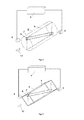
- Flowmeter comprises a microprocessor calculator of flow 1, which acts according to the typical principle of time-of-flight measurement, measurement tube 2, the cross-section of which is of circular form, two ultrasonic transducers 8 and 9, that emit an acoustic wave, which is subsequently divided by the partition 5 into two acoustic paths 3 of ultrasound wave propagation. While the ultrasound wave travels along the measurement tube, the half-cylinders 6 and 7 (on both sides of the partition) of optimum flow integration are formed in the acoustic paths 3.
- Fig 2 shows a version, where ultrasonic transducers 8 and 9 emit the ultrasound wave perpendicularly to the direction 12 of the flowing flow. The ultrasound wave is directed along the measuring tube 2 by means of mirrors 10 and 11.
- Fig. 2 shows a version of the measurement section, which is the most convenient for implementation in flow sensors of small dimensions (DN ⁇ 50).
- Fig. 3 shows a similar version to Fig. 2 , only in this case, the measurement tube consists of a pipe with rectangular cross-section and internal, longitudinally positioned, partition 5. Partition 5 divides the measuring tube with rectangular cross-section into two measurement tubes with triangular cross-section.
- Fig. 4 shows a version of the measurement section, where ultrasonic transducers 8 and 9 emit the ultrasound wave at a certain angle to the flow 12, that flows in the measuring tube with circular cross-section 2. In the course of propagation within the measurement tube 2 with partition 5, the ultrasound wave is divided into two half-cylinders 6 and 7 that integrate the flow.
- Fig. 4 shows a version of the measurement section, which is the most convenient for implementation in the flowmeters of bigger dimensions (DN>50).
- Fig. 5 shows a version which is similar to Fig. 4 , only in this case the measurement tube consists of a pipe with rectangular cross-section and internal, longitudinally positioned, partition 5. Partition 5 divides the measurement tube with rectangular cross-section into two measurement tubes with triangular cross-section.
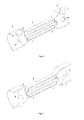
- Fig. 6 shows a perspective view in a longitudinal section of the same version of the measuring section ( Fig. 2 ).
- Fig. 7 shows a version, where ultrasonic transducers 8 and 9 are installed in the measurement section at both ends of the measuring tube with circular cross-section and directly emit the ultrasound wave into aforementioned measuring tube 2 with circular cross-section and partition 5 which is installed longitudinally inside the tube. In the course of propagation in the tube 2 of the measurement section with partition the ultrasound wave is divided into two half-cylinders 6 and 7.
- Fig. 7 shows a version of the measurement section, which is the most convenient for implementation in measurement sections of smaller dimensions (DN ⁇ 50).
- the proposed measurement section would enable attainment of advantages of analogous patented products that exist in the market, i.e. low sensitivity to distortions or changes of flow profile that are caused by type of liquid flow, as well as minimum requirements related to length of straight parts of pipeline before and after flowmeter, and alongside would enable a wider flow measurement range due to insensibility of the measurement section to the changes in the viscosity of liquid.
Landscapes
- Physics & Mathematics (AREA)
- Electromagnetism (AREA)
- Fluid Mechanics (AREA)
- General Physics & Mathematics (AREA)
- Measuring Volume Flow (AREA)
Applications Claiming Priority (1)
| Application Number | Priority Date | Filing Date | Title |
|---|---|---|---|
| LT2010087A LT5859B (lt) | 2010-10-14 | 2010-10-14 | Ultragarsinis srauto matuoklis |
Publications (2)
| Publication Number | Publication Date |
|---|---|
| EP2447681A2 true EP2447681A2 (fr) | 2012-05-02 |
| EP2447681A3 EP2447681A3 (fr) | 2014-04-30 |
Family
ID=45746898
Family Applications (1)
| Application Number | Title | Priority Date | Filing Date |
|---|---|---|---|
| EP11161146.3A Withdrawn EP2447681A3 (fr) | 2010-10-14 | 2011-04-05 | Débitmètre à ultrasons |
Country Status (2)
| Country | Link |
|---|---|
| EP (1) | EP2447681A3 (fr) |
| LT (1) | LT5859B (fr) |
Cited By (1)
| Publication number | Priority date | Publication date | Assignee | Title |
|---|---|---|---|---|
| US10900819B2 (en) | 2018-08-16 | 2021-01-26 | AXIOMA Metering, UAB | Ultrasonic flowmeter |
Citations (5)
| Publication number | Priority date | Publication date | Assignee | Title |
|---|---|---|---|---|
| FR2540624A1 (fr) | 1982-10-27 | 1984-08-10 | Danfoss As | Dispositif de mesure par ultra-sons muni d'un tube renfermant des pieces incorporees |
| WO1994002198A1 (fr) | 1990-08-31 | 1994-02-03 | Agribiotech, Inc. | Bol pour administration de medicaments retardee dans le temps |
| EP0708313A2 (fr) | 1994-10-20 | 1996-04-24 | Siemens Aktiengesellschaft | Débitmètre ultrasonique |
| EP0715155B1 (fr) | 1994-12-02 | 2001-04-11 | Siemens Aktiengesellschaft | Débitmètre à ultrason |
| EP1742024B1 (fr) | 2005-07-05 | 2008-02-06 | UAB Axis Industries | Débitmètre à ultrasons avec section transversale triangulaire |
Family Cites Families (5)
| Publication number | Priority date | Publication date | Assignee | Title |
|---|---|---|---|---|
| US4365518A (en) * | 1981-02-23 | 1982-12-28 | Mapco, Inc. | Flow straighteners in axial flowmeters |
| US4523478A (en) * | 1983-08-18 | 1985-06-18 | Nusonics, Inc. | Sonic flow meter having improved flow straighteners |
| GB2276240B (en) | 1993-03-16 | 1997-01-15 | British Gas Plc | Fluid flowmeter |
| JP4048964B2 (ja) * | 2003-01-31 | 2008-02-20 | 松下電器産業株式会社 | 超音波流量計 |
| JP4604520B2 (ja) * | 2004-03-10 | 2011-01-05 | パナソニック株式会社 | 流れ計測装置 |
-
2010
- 2010-10-14 LT LT2010087A patent/LT5859B/lt not_active IP Right Cessation
-
2011
- 2011-04-05 EP EP11161146.3A patent/EP2447681A3/fr not_active Withdrawn
Patent Citations (6)
| Publication number | Priority date | Publication date | Assignee | Title |
|---|---|---|---|---|
| FR2540624A1 (fr) | 1982-10-27 | 1984-08-10 | Danfoss As | Dispositif de mesure par ultra-sons muni d'un tube renfermant des pieces incorporees |
| WO1994002198A1 (fr) | 1990-08-31 | 1994-02-03 | Agribiotech, Inc. | Bol pour administration de medicaments retardee dans le temps |
| EP0708313A2 (fr) | 1994-10-20 | 1996-04-24 | Siemens Aktiengesellschaft | Débitmètre ultrasonique |
| EP0708313B1 (fr) | 1994-10-20 | 1998-06-10 | Siemens Aktiengesellschaft | Débitmètre ultrasonique |
| EP0715155B1 (fr) | 1994-12-02 | 2001-04-11 | Siemens Aktiengesellschaft | Débitmètre à ultrason |
| EP1742024B1 (fr) | 2005-07-05 | 2008-02-06 | UAB Axis Industries | Débitmètre à ultrasons avec section transversale triangulaire |
Cited By (1)
| Publication number | Priority date | Publication date | Assignee | Title |
|---|---|---|---|---|
| US10900819B2 (en) | 2018-08-16 | 2021-01-26 | AXIOMA Metering, UAB | Ultrasonic flowmeter |
Also Published As
| Publication number | Publication date |
|---|---|
| EP2447681A3 (fr) | 2014-04-30 |
| LT2010087A (en) | 2012-04-25 |
| LT5859B (lt) | 2012-08-27 |
Similar Documents
| Publication | Publication Date | Title |
|---|---|---|
| EP2513611B1 (fr) | Transducteur ultrasonore, débitmètre et procédé | |
| CN1327198C (zh) | 多普勒型超声流量计 | |
| CN1725019B (zh) | 钳式多普勒超声波流速分布仪 | |
| KR101798716B1 (ko) | 초음파 유량계 및 유량 계측 방법 | |
| EP0690974A4 (fr) | Construction d'un debitmetre | |
| CN110412134A (zh) | 流体测量装置 | |
| CN102066881B (zh) | 检测声学流量计中的液体的方法和系统 | |
| JP6552180B2 (ja) | 超音波流量計 | |
| EP2908103A1 (fr) | Débitmètre | |
| JP2015232519A (ja) | クランプオン式超音波流量計及び流量の計測方法 | |
| CN109477743B (zh) | 用于夹持式的超声波流量测量的方法和布置结构以及用于实现测量的主体 | |
| EP3063508B1 (fr) | Débitmètre pour mesure ultrasonique de la vitesse d'écoulement de fluides | |
| WO2013157990A1 (fr) | Débitmètre à ultrasons | |
| EP1742024B1 (fr) | Débitmètre à ultrasons avec section transversale triangulaire | |
| US11635316B2 (en) | Ultrasonic fluid measuring arrangement with at least two waveguide parts spaced apart on an outer wall of a measuring tube | |
| JP4453341B2 (ja) | 超音波流量計 | |
| JP4496258B2 (ja) | 超音波流量計 | |
| RU2715086C1 (ru) | Ультразвуковой расходомер | |
| RU118744U1 (ru) | Ультразвуковой расходомер | |
| RU231471U1 (ru) | Устройство формирования потока ультразвукового счётчика воды | |
| RU2331851C2 (ru) | Ультразвуковой расходомер | |
| LT5859B (lt) | Ultragarsinis srauto matuoklis | |
| RU27218U1 (ru) | Первичный преобразователь ультразвукового расходомера | |
| JP2010181321A (ja) | 超音波流量計 | |
| RU2277700C2 (ru) | Врезная секция ультразвукового расходомера |
Legal Events
| Date | Code | Title | Description |
|---|---|---|---|
| PUAI | Public reference made under article 153(3) epc to a published international application that has entered the european phase |
Free format text: ORIGINAL CODE: 0009012 |
|
| 17P | Request for examination filed |
Effective date: 20111129 |
|
| AK | Designated contracting states |
Kind code of ref document: A2 Designated state(s): AL AT BE BG CH CY CZ DE DK EE ES FI FR GB GR HR HU IE IS IT LI LT LU LV MC MK MT NL NO PL PT RO RS SE SI SK SM TR |
|
| AX | Request for extension of the european patent |
Extension state: BA ME |
|
| PUAL | Search report despatched |
Free format text: ORIGINAL CODE: 0009013 |
|
| AK | Designated contracting states |
Kind code of ref document: A3 Designated state(s): AL AT BE BG CH CY CZ DE DK EE ES FI FR GB GR HR HU IE IS IT LI LT LU LV MC MK MT NL NO PL PT RO RS SE SI SK SM TR |
|
| AX | Request for extension of the european patent |
Extension state: BA ME |
|
| RIC1 | Information provided on ipc code assigned before grant |
Ipc: G01F 1/66 20060101AFI20140321BHEP |
|
| R17P | Request for examination filed (corrected) |
Effective date: 20111129 |
|
| RBV | Designated contracting states (corrected) |
Designated state(s): AL AT BE BG CH CY CZ DE DK EE ES FI FR GB GR HR HU IE IS IT LI LT LU LV MC MK MT NL NO PL PT RO RS SE SI SK SM TR |
|
| 17Q | First examination report despatched |
Effective date: 20150402 |
|
| STAA | Information on the status of an ep patent application or granted ep patent |
Free format text: STATUS: THE APPLICATION IS DEEMED TO BE WITHDRAWN |
|
| 18D | Application deemed to be withdrawn |
Effective date: 20161101 |