EP2447703B1 - Dielektrische zytometrische Vorrichtung und dielektrisches/zytometrisches Zellsortierverfahren - Google Patents
Dielektrische zytometrische Vorrichtung und dielektrisches/zytometrisches Zellsortierverfahren Download PDFInfo
- Publication number
- EP2447703B1 EP2447703B1 EP11008237.7A EP11008237A EP2447703B1 EP 2447703 B1 EP2447703 B1 EP 2447703B1 EP 11008237 A EP11008237 A EP 11008237A EP 2447703 B1 EP2447703 B1 EP 2447703B1
- Authority
- EP
- European Patent Office
- Prior art keywords
- cell
- electrode
- channel member
- channel
- flow
- Prior art date
- Legal status (The legal status is an assumption and is not a legal conclusion. Google has not performed a legal analysis and makes no representation as to the accuracy of the status listed.)
- Not-in-force
Links
Images


Classifications
-
- G—PHYSICS
- G01—MEASURING; TESTING
- G01N—INVESTIGATING OR ANALYSING MATERIALS BY DETERMINING THEIR CHEMICAL OR PHYSICAL PROPERTIES
- G01N15/00—Investigating characteristics of particles; Investigating permeability, pore-volume or surface-area of porous materials
- G01N15/10—Investigating individual particles
- G01N15/1031—Investigating individual particles by measuring electrical or magnetic effects
- G01N15/12—Investigating individual particles by measuring electrical or magnetic effects by observing changes in resistance or impedance across apertures when traversed by individual particles, e.g. by using the Coulter principle
-
- B—PERFORMING OPERATIONS; TRANSPORTING
- B01—PHYSICAL OR CHEMICAL PROCESSES OR APPARATUS IN GENERAL
- B01L—CHEMICAL OR PHYSICAL LABORATORY APPARATUS FOR GENERAL USE
- B01L3/00—Containers or dishes for laboratory use, e.g. laboratory glassware; Droppers
- B01L3/50—Containers for the purpose of retaining a material to be analysed, e.g. test tubes
- B01L3/502—Containers for the purpose of retaining a material to be analysed, e.g. test tubes with fluid transport, e.g. in multi-compartment structures
- B01L3/5027—Containers for the purpose of retaining a material to be analysed, e.g. test tubes with fluid transport, e.g. in multi-compartment structures by integrated microfluidic structures, i.e. dimensions of channels and chambers are such that surface tension forces are important, e.g. lab-on-a-chip
- B01L3/502761—Containers for the purpose of retaining a material to be analysed, e.g. test tubes with fluid transport, e.g. in multi-compartment structures by integrated microfluidic structures, i.e. dimensions of channels and chambers are such that surface tension forces are important, e.g. lab-on-a-chip specially adapted for handling suspended solids or molecules independently from the bulk fluid flow, e.g. for trapping or sorting beads or physically stretching molecules
-
- B—PERFORMING OPERATIONS; TRANSPORTING
- B03—SEPARATION OF SOLID MATERIALS USING LIQUIDS OR USING PNEUMATIC TABLES OR JIGS; MAGNETIC OR ELECTROSTATIC SEPARATION OF SOLID MATERIALS FROM SOLID MATERIALS OR FLUIDS; SEPARATION BY HIGH-VOLTAGE ELECTRIC FIELDS
- B03C—MAGNETIC OR ELECTROSTATIC SEPARATION OF SOLID MATERIALS FROM SOLID MATERIALS OR FLUIDS; SEPARATION BY HIGH-VOLTAGE ELECTRIC FIELDS
- B03C5/00—Separating dispersed particles from liquids by electrostatic effect
- B03C5/005—Dielectrophoresis, i.e. dielectric particles migrating towards the region of highest field strength
-
- B—PERFORMING OPERATIONS; TRANSPORTING
- B03—SEPARATION OF SOLID MATERIALS USING LIQUIDS OR USING PNEUMATIC TABLES OR JIGS; MAGNETIC OR ELECTROSTATIC SEPARATION OF SOLID MATERIALS FROM SOLID MATERIALS OR FLUIDS; SEPARATION BY HIGH-VOLTAGE ELECTRIC FIELDS
- B03C—MAGNETIC OR ELECTROSTATIC SEPARATION OF SOLID MATERIALS FROM SOLID MATERIALS OR FLUIDS; SEPARATION BY HIGH-VOLTAGE ELECTRIC FIELDS
- B03C5/00—Separating dispersed particles from liquids by electrostatic effect
- B03C5/02—Separators
- B03C5/022—Non-uniform field separators
- B03C5/028—Non-uniform field separators using travelling electric fields, i.e. travelling wave dielectrophoresis [TWD]
-
- B—PERFORMING OPERATIONS; TRANSPORTING
- B01—PHYSICAL OR CHEMICAL PROCESSES OR APPARATUS IN GENERAL
- B01L—CHEMICAL OR PHYSICAL LABORATORY APPARATUS FOR GENERAL USE
- B01L2200/00—Solutions for specific problems relating to chemical or physical laboratory apparatus
- B01L2200/06—Fluid handling related problems
- B01L2200/0647—Handling flowable solids, e.g. microscopic beads, cells, particles
- B01L2200/0652—Sorting or classification of particles or molecules
-
- B—PERFORMING OPERATIONS; TRANSPORTING
- B01—PHYSICAL OR CHEMICAL PROCESSES OR APPARATUS IN GENERAL
- B01L—CHEMICAL OR PHYSICAL LABORATORY APPARATUS FOR GENERAL USE
- B01L2300/00—Additional constructional details
- B01L2300/06—Auxiliary integrated devices, integrated components
- B01L2300/0627—Sensor or part of a sensor is integrated
- B01L2300/0645—Electrodes
-
- B—PERFORMING OPERATIONS; TRANSPORTING
- B01—PHYSICAL OR CHEMICAL PROCESSES OR APPARATUS IN GENERAL
- B01L—CHEMICAL OR PHYSICAL LABORATORY APPARATUS FOR GENERAL USE
- B01L2300/00—Additional constructional details
- B01L2300/08—Geometry, shape and general structure
- B01L2300/0809—Geometry, shape and general structure rectangular shaped
- B01L2300/0816—Cards, e.g. flat sample carriers usually with flow in two horizontal directions
-
- B—PERFORMING OPERATIONS; TRANSPORTING
- B01—PHYSICAL OR CHEMICAL PROCESSES OR APPARATUS IN GENERAL
- B01L—CHEMICAL OR PHYSICAL LABORATORY APPARATUS FOR GENERAL USE
- B01L2300/00—Additional constructional details
- B01L2300/08—Geometry, shape and general structure
- B01L2300/0861—Configuration of multiple channels and/or chambers in a single devices
- B01L2300/0864—Configuration of multiple channels and/or chambers in a single devices comprising only one inlet and multiple receiving wells, e.g. for separation, splitting
-
- B—PERFORMING OPERATIONS; TRANSPORTING
- B01—PHYSICAL OR CHEMICAL PROCESSES OR APPARATUS IN GENERAL
- B01L—CHEMICAL OR PHYSICAL LABORATORY APPARATUS FOR GENERAL USE
- B01L2400/00—Moving or stopping fluids
- B01L2400/04—Moving fluids with specific forces or mechanical means
- B01L2400/0403—Moving fluids with specific forces or mechanical means specific forces
- B01L2400/0415—Moving fluids with specific forces or mechanical means specific forces electrical forces, e.g. electrokinetic
- B01L2400/0424—Dielectrophoretic forces
-
- G—PHYSICS
- G01—MEASURING; TESTING
- G01N—INVESTIGATING OR ANALYSING MATERIALS BY DETERMINING THEIR CHEMICAL OR PHYSICAL PROPERTIES
- G01N15/00—Investigating characteristics of particles; Investigating permeability, pore-volume or surface-area of porous materials
- G01N15/10—Investigating individual particles
- G01N2015/1028—Sorting particles
Definitions
- the present disclosure relates to a dielectric cytometric apparatus for analyzing and sorting cells as well as a dielectric cytometric cell sorting method.
- flow cytometry In the fields of life sciences and medical researches or in the fields of medical cares such as clinical practices, an analysis method referred to as flow cytometry is adopted.
- liquid composed of cells individually freed from each other is taken as a sample.
- liquid serving as a sample is driven to flow through the inside of a flow channel pipe.
- a signal detection section installed in the flow channel pipe carries out a certain analysis/measurement on individual cells flowing through the signal detection section. Cells having measured signals approximating each other are considered to be cells of the same type.
- signals measured for a number of cells included in the sample liquid are analyzed in order to identify the type of cells included in a cell group serving as the sample and calculate a cell-type cell count representing the number of cells included in the cell type.
- a ratio of the cell-type cell count to the total number of cells is also possible.
- the analysis method adopted in the flow cytometry is classified into large categories, that is, an optical analysis method and an electrical analysis method.
- optical analysis method a combination of only a fluorescent detection method and a light scattering detection method is adopted.
- the principle of the fluorescent detection method is explained as follows.
- the surface antigen is by no means limited to one type. Thus, by identifying the type of the surface antigen and the number of surface antigens included in the type of the antigen, it is possible to identify the cell type to which the cells pertain. If the surface-antigen molecules are known, it is possible to synthesize molecules, which are specifically joinable to the surface-antigen molecules, to the surface-antigen molecules. The molecules specifically joinable to the surface-antigen molecules are referred to as antibody molecules for the surface antigens. In addition, it is also possible to chemically join fluorescent labeling molecules to the antibody molecules.
- a fluorescent labeling molecule is a molecule which generates fluorescent light if light having a wavelength in a specific wavelength band is radiated to the molecule. That is to say, fluorescent labeling antibodies generating fluorescent light beams having different wavelengths are each synthesized with a surface antigen molecule used for characterizing the cell type assumed to be included in a cell group serving as a subject of an analysis. The composite of all these fluorescent labeling antibodies is taken as a labeling test reagent. If this labeling test reagent is added to liquid solution, each of cells of the labeling test reagent is labeled with a fluorescent molecule which varies from cell type to cell type to which the cells pertain.
- a signal detection section installed in a flow channel pipe of a flow cytometric apparatus also referred to as a flow cytometer
- laser light is radiated to a cell passing through the signal detection section.
- the surface-antigen molecules of individual cells and fluorescent labeling molecules joined to antibody molecules specifically joined to the surface-antigen molecules are excited, generating fluorescent light having a wavelength peculiar to the fluorescent labeling molecules.
- the fluorescent light is detected in order to count the number of cells for every cell type. This method is adopted widely.
- the so-called flow cytometry is intended to imply essentially this method.
- the flow cytometer put into the market is used not only for obtaining the existing state of surface antigen molecules but also additional information such as cell dimensions and the internal density of the cells. Thus, the flow cytometer is used for measuring the strength of laser light scattered by cells at the same time.
- Document US 7,294,249 B2 discloses a differential detection structure having two electrode pairs along a measurement portion of the flow channel. Furthermore, in order to sequentially isolate the cells a preparation area is needed being arranged upstream of the two electrode pairs. In the preparation area an additional separation electrode pair is arranged together with a further separation electrode. The analysis of flowing cells is based on measuring the impedance.
- the electrical analysis method based on only a DC resistance or a combination of a DC resistance and an AC resistance is used in some flow cytometers by combining the electrical analysis method with the optical analysis method.
- an automatic blood-cell counting apparatus for counting, among others, the number of red-blood cells, the number of white-blood cells and the number of blood platelets. Normally, the automatic blood-cell counting apparatus is differentiated from the flow cytometer. From the standpoint of the operation principle of the automatic blood-cell counting apparatus, however, the automatic blood-cell counting apparatus can be said to be a flow cytometer in a broader sense.
- flow cytometer is used to imply both the automatic blood-cell counting apparatus and the automatic blood-cell counting apparatus which is a flow cytometer in a broader sense.
- the flow cytometer adopting the electrical analysis method is implemented by adopting also the optical analysis method.
- Applications include not only analyses of cells included in liquid solution, but also possibly sorting of only cells included in a specific cell type from other cells by making use of results of the analyses. For example, there is a case in which a cell type appearing in peripheral blood exists due to a sort of blood cancer. In this case, only the cell type is sorted and a gene analysis or a protein analysis is carried out on the cell type. By conducting such an analysis, it is quite within the bounds of possibility that a clue as to what has caused the blood-cancer disease is obtained. For example, the clue may suggest that the blood-cancer disease has been caused by a gene abnormality or the like. As another example, in an attempt to induce an iPS cell from a cell of a human being, not every cell of the human being is induced into an iPS cell. It is thus necessary to sort only iPS cells from cultured cells.
- sorter is provided in upper-level models of the flow cytometer put into the market.
- the fluorescent flow cytometer is a flow cytometer based on a fluorescent detection method selected among optical analysis methods.
- the big problem is that, strictly speaking, the original state of the cell used as the subject of control is different from the state of a fluorescently labeled cell. If an antibody molecule is joined to a surface antigen molecule, chemical excitement is added to the inside of the cell so that a multi-stage signal transmission reaction may probably take place. However, the effect of such a small change can be regarded as a small effect so that the cell can be normally used for a research purpose.
- the obtained cell system may be re-implanted to the inside of the body of the patient for the purpose of a medical care.
- Typical examples of the biochemical process are a culturing process, an activation process and a differentiation induction process.
- no safety is assured for the operation to re-implant cells in which fluorescent labeling antibody molecules have been rejoined to surface antigen molecules or re-implant a system of cells derived from such cells to the inside of the body of the patient. It is thus desirable to provide a technology capable of analyzing cells and sorting cells by sustaining the original living state of the cells as it is without labeling the cells.
- the electrical analysis method does not require a labeling substance.
- the cell sorting apparatus can be used for the purposes of a regenerative medical care and a cell medical care.
- the existing Coulter counter it is possible to obtain only limited measured data based on only a DC resistance or a combination of a DC resistance and an AC resistance.
- a capability demonstrated by the Coulter counter as a capability of sorting different cell types is so inadequate.
- a dielectric cytometric apparatus employing a flow channel, a first electrode pair, an analysis unit, a second electrode pair and a cell sorting unit.
- the flow channel includes a channel member (stenosis channel) through which a single cell is capable of flowing and branch channels provided on the downstream side of the channel member (stenosis channel) as branch channels for sorting cells included in liquid flowing through the flow channel.
- a channel member stenosis channel
- branch channels provided on the downstream side of the channel member (stenosis channel) as branch channels for sorting cells included in liquid flowing through the flow channel.
- the first electrode pair to which an AC voltage is applied is capable of generating an AC electric field on the channel member (stenosis channel)
- the analysis unit By generating the AC electric field generated on the channel member (stenosis channel) by the AC voltage applied to the first electrode pair, the analysis unit is capable of measuring a complex dielectric constant depending on the cell for each of the cells each flowing through the channel member (stenosis channel) .
- the second electrode pair to which a voltage is applied is capable of generating an electric field on a flow-channel portion on the downstream side of channel member (stenosis channel) but on the upstream side of the branch channels.
- the cell sorting unit By generating the electric field on the flow-channel portion by the voltage applied to the second electrode pair, on the basis of the complex dielectric constant measured by the analysis unit, the cell sorting unit is capable of providing a dielectrophoretic force to the cells and sorting the cells by making use of the branch channels.
- the analysis unit measures a complex dielectric constant depending on the cell and, on the basis of a signal based on the complex dielectric constant, the cell sorting unit sorts the cells by making use of a dielectrophoretic force generated by an electric field created on the downstream side of the channel member (stenosis channel). That is to say, the dielectric cytometric apparatus is capable of both electrically analyzing (or measuring) and electrically sorting cells without adoption of the optical analysis method.
- the analysis unit generates a superposed voltage signal including a superposed AC voltage having a plurality of frequencies and carries out a Fourier transform on signals of a voltage and a current, which are measured when the single cell passes through the channel member (stenosis channel), in order to calculate the complex dielectric constant for every one of the frequencies.
- a superposed voltage signal including a superposed AC voltage having a plurality of frequencies, that is, a multi-point frequency is applied to the first electrode pair and a Fourier transform is carried out in order to obtain a frequency spectrum distribution for every cell.
- the analysis unit stores in advance reference information to be used as a reference of the complex dielectric constant measured for every cell.
- the cell sorting unit refers to the complex dielectric constant measured by the analysis unit and the reference information on a real-time basis and creates the electric field on the basis of information indicating whether or not the complex dielectric constant is within the range of the reference information.
- a dielectric cytometric cell sorting method includes the step of causing fluid including cells to flow through a flow channel including a channel member (stenosis channel) and branch channels.
- An AC electric field is created on the stenosis channel.
- an electric field is created on a flow-channel portion on the downstream side of the channel member (stenosis channel) but on the upstream side of the branch channels in order to apply a dielectrophoretic force to the cells so that the cells can be sorted by making use of the branch channels.
- a complex dielectric constant is measured for every cell passing through the channel member (stenosis channel) of the flow channel and a dielectrophoretic force is generated by an electric field created on a flow-channel portion on the downstream side of the channel member (stenosis channel) but on the upstream side of the branch channels on the basis of the measured complex dielectric constant and applied to cells so that the cells can be sorted by making use of the branch channels. That is to say, it is possible to carry out a process of both analyzing (or measuring) and sorting cells electrically without adoption of the optical analysis method.
- Suspension liquid including cells is injected into a measurement container having the shape resembling a parallel-plate capacitor composed of a pair of electrode plates facing each other.
- An AC voltage is applied between the electrode plates and a current flowing due to the application of the AC voltage is measured in order to find a complex resistance (or a complex impedance) between the electrode plates. If the frequency of the AC voltage is changed, the measured complex resistance also changes.
- the complex resistance can be measured by making use of a precise impedance analyzer put into the market.
- the complex resistance found in this way as a complex resistance depending on the frequency can be converted into the complex dielectric constant of the suspension liquid including cells by correcting some factors such as a factor depending on the shape of the measurement container and a factor depending on the transmission characteristic of an electrical wire connecting the complex-resistance measuring apparatus to the measurement container.
- some factors such as a factor depending on the shape of the measurement container and a factor depending on the transmission characteristic of an electrical wire connecting the complex-resistance measuring apparatus to the measurement container.
- the frequency-dependent characteristic of the complex resistance is referred to the dispersion of the complex resistance or a dielectric constant spectrum.
- FIG. 1 is a graph representing models of dispersions of a complex dielectric constant.
- the real part of the relaxation of the complex dielectric constant for the cell suspension liquid has about a constant value independent of the frequency. As the frequency is increased, this real part considerably decreases in the so-called dielectric relaxation phenomenon in a frequency area around about 1 MHz. If the frequency is further increased, the real part has an all but constant small value.
- the imaginary part of the relaxation of the complex dielectric constant has a frequency characteristic with a peak value in the frequency area in which the dielectric relaxation phenomenon occurs.
- the dispersion of the complex dielectric constant of the suspension liquid can be expressed by a single relaxation function such as a Cole-Cole function or expressed by superposition of a plurality of relaxation functions.
- a single relaxation function such as a Cole-Cole function
- the variables can be optimized.
- variables characterizing a dispersion curve include a relaxation strength and a relaxation frequency.
- These dielectric variables are closely related to the structure and physicality of the cell.
- Japanese Patent Laid-open No. 2009-42141 discloses a method for inferring the electrical physicality value of a facet composing a cell from a complex dielectric constant. In this case, the facet composing a cell represents, among others, a cell film and cell properties.
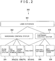
- FIG. 2 is a block diagram showing the entire configuration of a dielectric spectro-cytometric apparatus 300 as an embodiment of the dielectric cytometric apparatus according to the present disclosure.
- the dielectric spectro-cytometric apparatus 300 is configured to have three stage layers.
- the stage layer on the top is a user interface 301.
- the user interface 301 is provided between the user and the main body of the dielectric spectro-cytometric apparatus 300.
- the user interface 301 plays the role to receive information entered by the user to the dielectric spectro-cytometric apparatus 300 and show a measurement result generated by the dielectric spectro cytometric apparatus 300 to the user.
- a typical example of the information entered by the user is measurement conditions.
- the user interface 301 is physically implemented by a terminal of a computer and a program invoked in the computer.
- a hardware control system 302 and a software control system 303 are provided below the user interface 301.
- the hardware control system 302 is hardware for controlling configuration elements of the dielectric spectro-cytometric apparatus 300, carrying out measurements and recording measured data.
- the hardware control system 302 also includes programs to be executed for controlling the configuration elements of the dielectric spectro-cytometric apparatus 300, carrying out measurements and recording measured data.
- the hardware control system 302 is hardware for controlling a flow channel system 304, a cell sorting mechanism 305, a sorting-signal generator 306 and an analyzer 307. It is a main object of flow channel system 304 to introduce a cell used as a sample into a signal detection section.
- the analyzer 307 is an analyzer for measuring a signal caused by the introduced cell.
- the analyzer 307 includes a complex analyzer AN to be described later.
- the sorting-signal generator 306 is a generator for generating a signal used for sorting cells whereas the cell sorting mechanism 305 is a mechanism for sorting the cells on the basis of the signal generated by the sorting-signal generator 306.
- the software control system 303 has analysis software 308 and a data management system 309.
- the data management system 309 is a system for managing and saving the recorded measured data received from the analyzer 307.
- the data management system 309 includes a data management program and a data server.
- the analysis software 308 is software for extracting meaningful information from the measured data.
- the hardware control system 302, the software control system 303 and the analyzer 307 collaborate with each other to function as an analysis unit.
- the hardware control system 302 and the sorting-signal generator 306 collaborate with each other to function as a cell sorting unit.
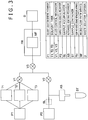
- FIG. 3 is a block diagram showing the configuration of the flow channel system 304 included in the dielectric spectro cytometric apparatus 300 shown in FIG. 2 .
- the flow channel system 304 has a micro flow channel device MF for detecting a signal and other sections referred to as fluid control mechanisms VI, V2 and V3. Due to operations of the fluid control mechanisms VI, V2 and V3, liquid solution is introduced into the micro flow channel device MF from an external source and, after a complex resistance has been measured by the signal detection section, the liquid solution is discharged back to the external source. Serving as a sample, the liquid solution is fluid including cells. It is to be noted that, conceptually, the liquid solution includes dispersion liquid or suspension liquid. The technical term 'liquid solution' used in the following description conceptually includes dispersion liquid or suspension liquid.
- Elements composing each of the fluid control mechanisms VI, V2 and V3 typically include a container (or a tank), a compressed-air supplier (or a compressor), a pump, a valve and a pipe.
- the container (or the tank) is an element for accumulating dispersion solvent and/or cleaning liquid whereas the compressed-air supplier (or a compressor) is en element for pressing liquid solution.
- the pump is an element for sucking sample liquid solution and introducing the sample liquid solution into the micro-flow-channel device MF.
- the valve is an element for controlling the flow of liquid solution whereas the pipe is an element for connecting elements to each other.
- the elements composing the flow channel system 304 are by no means limited to the elements described above. That is to say, other elements can be used for constructing the flow channel system 304 as long as the other elements are capable of achieving the object of the flow channel system 304.
- the cell liquid solution is injected into a sample tank ST which is provided inside the dielectric spectro cytometric apparatus 300.
- Liquid solvent tanks T1, T2 and T3 typically contain pure water, PBS buffering liquid or cleaning liquid such as SDS liquid solution.
- the number of tanks and the type of the solvent are by no means limited to these examples.
- a solvent solution-sending mechanism P1 sends liquid in order to properly drive the fluid control mechanisms V1 and V3.
- a flow channel pipe including the micro flow channel device MF mounted on a storage metallurgical apparatus FH is cleaned and then filled up with the PBS buffering liquid.
- an automatic sample sorting mechanism AS absorbs a sample having a proper quantity from the sample tank ST.
- the sample is pulled in a sample accumulator SL which is referred to as the so-called sample loop.
- the sample accumulator SL is not element provided specially but, in actuality, a part of the flow channel pipe.
- a sample solution-sending mechanism P2 sends the sample in the sample accumulator SL to the micro flow channel device MF.
- the fluid control mechanisms V2 and V3 the sample is capable of flowing through the micro flow channel device MF and exhausted to a waste solution disposal D.
- the pipe is cleaned in accordance with the same fluid control procedure as the adjustment which has been carried out prior to the injection of the sample as the adjustment of the flow channel pipe.
- FIG. 4 is a block diagram showing the configuration of the micro-flow-channel device MF.
- the micro flow channel device MF is connected fluidically to an external flow channel pipe and connected electrically to an external complex-resistance analyzer.
- the complex-resistance analyzer can be a portion or all of the analyzer 307 employed in the dielectric spectro cytometric apparatus 300 shown in FIG. 2 .
- the micro flow channel device MF is mounted on the storage metallurgical apparatus FH which implements the connections between the micro flow channel device MF and the external flow channel pipe as well as between the micro flow channel device MF and the external complex-resistance analyzer.
- a proper structure of the micro flow channel device MF used in this embodiment and a proper method for manufacturing the micro flow channel device MF are disclosed in Japanese Patent Laid-open No. 2010-181399 and Japanese Patent Laid-open No. 2008-279382 respectively.
- a pair of electrodes EL1 and EL2 are formed inside each of flow channels FC1 and FC2 each having dimensions sufficiently greater than the dimensions of a cell.
- a member NC having dimensions of about the same order as the dimensions of a cell is provided.
- the member NC is the stenosis channel described earlier.
- the channel member (stenosis channel) NC Since the electrical resistance of the channel member (stenosis channel) NC is very large in comparison with those of the flow channels FC1 and FC2, most of a voltage applied between the electrodes EL1 and EL2 forming a pair is virtually applied to only the channel member (stenosis channel) Thus, even if the electrodes EL1 and EL2 forming a pair are spatially separated from each other, the channel member (stenosis channel) functions as the signal detection section mentioned before. Details of the principle are described in Japanese Patent Laid-open No. 2010-181399 . This principle will be explained later too.
- the flow channel FC1 is connected to a flow channel pipe created in the storage metallurgical apparatus FH by proper joining section J2.
- the flow channel FC2 is connected to the flow channel pipe created in the storage metallurgical apparatus FH by proper joining section J3.
- a typical example of the proper joining sections J2 and J3 is an O ring.
- the storage metallurgical apparatus FH is connected to an external pipe by proper joining sections J1 and J4.
- a typical example of the proper joining sections J1 and J4 is a pipe joining component of the liquid chromatography.
- the electrodes EL1 and EL2 forming a pair are connected to the outside of the micro flow channel device MF by pull-out wires L1 and L2 respectively.
- the electrodes EL1 and EL2 forming a pair are also connected to a complex-resistance analyzer through proper connection components.
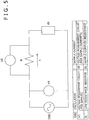
- FIG. 5 is a diagram showing a circuit for implementing a IV method for measuring a complex resistance.
- An oscillator OSC employed in the circuit shown in the figure is a section for generating a voltage having a sinusoidal waveform.
- the voltage applied to the sample is measured by a voltage measurement circuit V1. Since a current I flowing through the sample cannot be measured directly, a voltage measurement circuit V2 is used for measuring a voltage appearing between the two ends of a resistor R having a known low resistance. Thus, the current I flowing through the sample can be computed from the voltage appearing between the two ends of the resistor R.
- the low-resistance resistor R may be replaced by a device generating a small loss.
- the very small resistance change is a change caused by a single cell passing through the channel member (stenosis channel) NC serving as the signal detection section.
- FIG. 6 is a diagram showing an embodiment implementing a measurement circuit for measuring the complex resistance of a single cell.
- the circuit shown in the figure is based on the IV method.
- a plurality of input voltages having frequencies different from each other are synthesized with each other by superposing the input voltages on each other and are applied between electrodes.
- a Fourier transform is subsequently applied to an output voltage and an output current in order to measure a complex resistance for every frequency.
- An electrode EL and the ground electrode G which are employed in the circuit shown in FIG. 6 correspond to respectively the electrode pairs EL1 and EL2 of the micro flow channel device MF shown in FIG. 4 . In actuality, the ground electrode G is used as a common electrode.
- each of these voltage and current signals is amplified by an amplifier. Since the amplifier is combined with a band pass filter if necessary, each of the signals does not necessarily represent a single cell.
- a signal including a plurality of components having frequencies different from each other is distributed by a distributor D1 or D2 to n sub-frequency bands. This is because it is difficult to make use of one analog circuit for processing the entire frequency band used for grasping a dielectric relaxation phenomenon of the cell.
- an analog signal passing through an analog filter AFVi or AFIi composed of devices having characteristics proper for the band is converted by an analog/digital converter ADi into a digital signal.
- the digital signal obtained as the result of the conversion is processed by a digital-signal processing circuit DPi.
- the measured dispersion of the complex resistance is analyzed typically at five stages described as follows.
- the measured complex resistances are calibrated by taking the transmission characteristic of the measurement system into consideration. From the calibrated complex resistances, the electrical capacitance C of the sample and the conductance G of the sample are obtained. In the following description, the electrical capacitance C and the conductance G are referred to as CG data of the sample.
- a signal of a cell is extracted from the CG data depending on the time. That is to say, a peak is extracted from the CG data whereas a base line is calculated from data before and after the peak. Then, a difference between the value of the peak and the base line is computed in order to find changes ⁇ C of the capacitance C and changes ⁇ G of the conductance G at all frequency points.
- the changes ⁇ C and the changes ⁇ G are referred to as ⁇ C ⁇ G data.
- a distribution of the ⁇ C ⁇ G data for every cell is converted into a frequency dispersion of the dielectric constant ⁇ and the specific electric conductivity ⁇ .
- the dielectric constant ⁇ and the specific electric conductivity ⁇ are referred to as ⁇ data.
- the frequency dispersion of the ⁇ data is a dielectric dispersion.
- a relation table computed in advance is referred to in order to calculate the electrical physicality value of the cell configuration facet from the dielectric variables.
- the distributions of the electrical physicality value for detected cells are classified into proper and small cell groups each representing one of cell types. Then, for each of the cell types, quantities such as the average and variance of the electrical physicality values are calculated.
- the K562 cell is a cultured cell line caused by the human erythroblastoid leukemia disease whereas the Jurkat cell is a cultured cell line caused by a lymphocyte tumor of the human leukemia disease T.
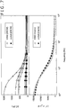
- a graph on the upper side of FIG. 7 represent results of measurements carried out by the dielectric spectro-cytometric apparatus 300. Data points represented by different symbols on the graph depend on different cells. That is to say, the graph is plotted to represent pieces of data at eight frequency points for a single cell. The graph show results of adapting data points to a relaxation function.
- the vertical axis for the graph on the upper side of FIG. 7 represents the electrical-capacitance change computed from the measured complex resistance.
- the electrical-capacitance change can be converted into the real part of a complex dielectric constant.
- the change ⁇ C of the electrical capacitance is shown as it is.
- Data computed from the imaginary part of the complex dielectric constant as data representing the conductance G is also obtained but not shown in the figure.
- the imaginary part of the complex dielectric constant is the complex resistance.
- a graph on the lower side of FIG. 7 represent the real part of the dispersion of the dielectric constant of the liquid solution for the K562 and Jurkat cells in the same way as the graph on the upper side.
- the liquid solution includes about 10 8 cells. That is to say, the graph on the upper side of FIG. 7 represents data for a single cell whereas the graph on the lower side of the same figure represent averages of data for a number of cells.
- data adapted to a relaxation function is obtained, obviously making it possible to implement a quantitative measurement of the dielectric constant for a single cell. That is to say, it is now obvious that the dielectric spectro-cytometry can be realized.
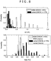
- FIG. 8 is a set of histograms showing a dielectric variable obtained by adaption of the complex dielectric constant dispersion of a single cell to a relaxation function. That is to say, FIG. 8 is a set of histograms showing ⁇ C representing a relaxation amplitude and a critical frequency fc at which the relaxation occurs.
- the figure shows different distributions of the dielectric variable for different cultured cells which are the K562 and Jurkat cells described above. The figure thus indicates that the dielectric spectro cytometry is capable of classifying cells into different cell types.
- FIG. 9 is a block diagram showing the configuration of a cell sorting system.
- the sorting-signal generator TR which is the sorting-signal generator 306 shown in FIG. 2 receives a complex resistance (or a complex dielectric constant) from the complex analyzer AN which is the analyzer 307 shown in FIG. 2 , a value measured at every frequency point is compared with reference information set in advance.
- the reference information set in advance is information including a complex resistance measured in the past for each cell at the frequency point.
- the reference information set in advance is information including a complex dielectric constant found on the basis of such a complex resistance.
- the sorting-signal generator TR generates a sorting signal serving as a trigger signal for sorting cells.
- a sorting-signal generator TR determines whether or not the measured complex resistance or the measured complex dielectric constant falls within a range centered at the reference information set in advance to serve as information corresponding to the measured complex resistance or the measured complex dielectric constant respectively. If the measured complex resistance or the measured complex dielectric constant falls within the range, the sorting-signal generator TR generates a trigger signal. To put it concretely, on the basis of the logical product of information obtained as a result of the comparison, the sorting-signal generator TR determines whether or not the cell is to be taken as a subject of sorting. If the cell is to be sorted, the sorting-signal generator TR generates a trigger signal and outputs the trigger signal to the cell-sorting mechanism CS which is the cell sorting mechanism 305 shown in FIG. 2 .
- the cell-sorting mechanism CS receiving the trigger signal determines a proper timing with which a cell passes through the cell sorting section of the micro flow channel device MF.
- the cell-sorting mechanism CS receiving the trigger signal determines a proper timing with which a cell passes through a portion immediately preceding the branch channels and generates a driving force such as a dielectrophoretic force or a fluid force with the proper timing in order to change the channel through which the cell flows.
- a driving force such as a dielectrophoretic force or a fluid force with the proper timing in order to change the channel through which the cell flows.
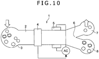
- FIG. 10 is a diagram showing a model of a dielectric spectro-cytometric apparatus 300 according to an embodiment of the present disclosure
- FIG. 11 is a perspective diagram showing a micro-flow-channel device MF included in the flow channel system 304 of the dielectric spectro-cytometric apparatus 300 shown in FIG. 10 .
- the flow channel system 304 is included in the dielectric spectro-cytometric apparatus 300.
- the micro flow channel device MF includes an injection section 3, a measurement section 4, a cell sorting section 5, cell fetching sections 6 and 7 as well as an outflow section 10 on a flow channel 2 created in the micro flow channel device MF.
- the injection section 3, the measurement section 4, the cell sorting section 5, the cell fetching sections 6 and 7 as well as the outflow section 10 are arranged along the flow channel 2 in a direction from the upstream side of the flow channel 2 to the downstream side of the flow channel 2.
- the injection section 3 is a section for injecting liquid (or fluid) including a sampled cell by making use of a pressure control apparatus to be explained later by referring to typically FIG. 16 and figures subsequent to FIG. 16 .
- the liquid injected by the injection section 3 flows through the flow channel 2.
- the measurement section 4 is a section for measuring the complex dielectric constant of a cell at frequency points in a frequency range of typically 0.1 MHz to 50 MHz for each individual cell flowing through the flow channel 2.
- the frequency range is a range in which the dielectric relaxation phenomenon of a cell occurs.
- the measurement section 4 measures the complex dielectric constant of a cell at typically three or more frequency points.
- the measurement section 4 measures the complex dielectric constant of a cell at 10 to 20 frequency points.
- the analyzer 307 including the measurement section 4 adopts the technique described before to determine whether or not the measured cell is a cell to be fetched from the micro flow channel device MF and to be used in an application such as an examination or a recycling process. If the analyzer 307 determines that the measured cell is a cell to be fetched from the micro flow channel device MF and to be used in such an application, the measurement section 4 generates a sorting signal.
- the measurement section 4 conceptually has the main function of the analyzer 307 described before and includes some of the mechanism of the flow channel system 304 also described before.
- the cell sorting section 5 selects a desired cell from a plurality of cells injected by the injection section 3 as cells of different types and supplies the desired cell to the cell fetching section 6 and the other cells to the cell fetching section 7.
- the cell sorting section 5 conceptually has the main function of the sorting-signal generator 306 described before and includes some of the mechanism of the flow channel system 304 also described before.
- An electric-field application section 8 provided in the cell sorting section 5 is a section capable of applying an electric field having a gradient in a direction different from the X direction in which the fluid flows.
- the electric-field application section 8 is capable of applying an electric field having a gradient in a Y direction perpendicular to the X direction.
- the electric-field application section 8 does not apply an electric field.
- the electric-field application section 8 applies an electric field.
- the electric-field application section 8 does not apply an electric field but, when the cell sorting signal serving as a trigger signal is not received to become a generated operation signal, on the other hand, the electric-field application section 8 applies an electric field.
- a flow splitting section 9 of the cell sorting section 5 is a section for directing a cell to which the electric-field application section 8 does not apply the electric field to the cell fetching section 7 through a branch channel 2b and a cell experiencing the electric field generated by the electric-field application section 8 to the cell fetching section 6 through a branch channel 2a.
- the cell fetching sections 6 and 7 are connected to the outflow section 10 through the flow channel 2.
- the fluid passing through the cell fetching sections 6 and 7 is exhausted by a pump from the outflow section 10 to an external destination.
- the micro flow channel device MF has a substrate 12 and a member 13 made from a high-molecular film or the like to form the shape of a sheet.
- the flow channel 2 On the substrate 12, there are provided the flow channel 2, the branch channels 2a and 2b which are each a portion of the flow channel 2, a liquid injection section 3a functioning as the injection section 3, the flow splitting section 9 which is a portion of the flow channel 2, the cell fetching sections 6 and 7 as well as the outflow section 10.
- the flow channel 2, the branch channels 2a and 2b, the liquid injection section 3a, the flow splitting section 9, the cell fetching sections 6 and 7 as well as the outflow section 10 are constructed into a configuration provided on the substrate 12 by creating grooves or the like on the surface of the substrate 12 and by covering the surface with the member 13. In this way, the flow channel 2 is created.
- a cell injection section 3b into which the fluid including cells is injected is configured by providing a tiny hole on the member 13 to serve as a channel member (stenosis channel) channel.
- the fluid including cells is dropped on the cell injection section 3b by making use of a pipette, the fluid flows through the flow channel 2 to the downstream side of the flow channel 2 so that the fluid is mixed up with liquid flowing along the flow channel 2 through the channel member (stenosis channel). Since the channel member (stenosis channel) is a tiny hole, cells never flow through the channel member (stenosis channel) to the flow channel 2 as a group. Instead, a single cell is capable of passing through the channel member (stenosis channel) sequentially one cell after another to the flow channel 2.
- a pair of measurement electrodes 4a and 4b for measuring a complex resistance or a complex dielectric constant is provided to sandwich the channel member (stenosis channel).
- the pair of measurement electrodes 4a and 4b is provided to serve as a first electrode pair.
- the measurement electrode 4a which is a specific one of the electrodes is provided on the front face of the member 13 having a sheet shape whereas the measurement electrode 4b serving as the other electrode is provided on the rear face of the member 13 having a sheet shape.
- An electrode pair composing the electric-field application section 8 is also provided on the rear face of the sheet-shaped member 13. This electrode pair will be described later.
- the cell fetching sections 6 and 7 are covered by the sheet-shaped member 13 provided above the cell fetching sections 6 and 7. However, a cell can be fetched through a pipette by stinging the member 13 having a sheet shape with the pipette.
- An electrode pad 14 is a section for fetching a signal detected by the measurement electrodes 4a and 4b and outputting the fetched signal to an external signal recipient. The fetched signal is also transmitted to the analyzer 307.
- An electrode pad 15 is a section for receiving an operation signal generated from a trigger signal based on measurement information of the complex dielectric constant of the analyzer 307 as a trigger.
- the trigger signal is the trigger signal generated by the sorting-signal generator 306.
- the received operation signal is transmitted to the electrode pair composing the electric-field application section 8 as described above.
- a through hole 26 is a hole which is used for determining a position at which the micro flow channel device MF is connected to the main body having the analyzer and other sections in the apparatus.
- FIG. 12 is a diagram, as an example for better understanding the invention, showing the top view of the configuration of a cell sorting section 5 employed in the micro-flow-channel device MF shown in FIG. 11
- FIG. 13 is a diagram, as an example for better understanding the invention, showing a cross section along a line A-A of the configuration of the cell sorting section 5 shown in FIG. 12 .
- the cell sorting section 5 has the electric-field application section 8.
- the cell sorting section 5 is a section composing a portion of the cell sorting unit explained before.
- the electric-field application section 8 has electrodes 16 and 17 each provided at a position determined in advance on the flow channel 2.
- the electrodes 16 and 17 are provided at typically positions facing each other to sandwich the flow channel 2 in a Y direction different from an X direction in which the fluid flows through the flow channel 2.
- the electrodes 16 and 17 are provided on the rear face of the member 13 having a sheet shape.
- the rear face of the member 13 is a ceiling face inside the flow channel 2.
- the electrode 16 is typically an electrode to which a signal is applied.
- the electrode 16 is configured to have a number of electrode pointers 16a each protruding in a direction toward the electrode 17.
- the electrode 17 is typically the common electrode.
- the electrode 17 is configured to have neither protrusions nor dents in a direction in which the electrode 17 faces the electrode 16.
- a combination of one electrode pointer 16a and the electrode 17 is referred to as an operation-electrode pair 18 functioning as a second electrode pair.
- a cell C whose flowing direction has been changed by a dielectrophoretic force generated by an electric field applied by the electric-field application section 8 is directed to the cell fetching section 6 by making use of the branch channel 2a.
- a cell is injected to a position sided to the cell fetching section 7.
- This cell injected to a position sided to the cell fetching section 7 is put in a non-active state and flows inside the flow channel 2 to the cell fetching section 7 through the position sided to the cell fetching section 7 by sustaining its flowing direction as it is and through the flow splitting section 9 to enter the branch channel 2b connected to the cell fetching section 7 as shown in FIG. 12 .
- a non-active state is a state in which a cell not serving as the subject of cell sorting does not experience an electric field at the electric-field application section 8 when the cell is passing through the electric-field application section 8.
- a non-active state is a state in which a cell serving as the subject of cell sorting experiences a dielectrophoretic force generated by an electric field applied by the electric-field application section 8 when the cell is passing through the electric-field application section 8.
- each operation-electrode pair 18 applies an electric field having a gradient in the Y direction.
- a cell passing through a operation-electrode pair 18 gradually changes its flow channel and branches to the side of the cell fetching section 6 by flowing through the branch channel 2a.
- the dielectrophoretic force applied to a cell in an electric field having a strength not causing a fatal damage to the cell is generally extremely small in comparison with a viscosity resistance force applied to a cell flowing through water at a velocity of the order of several mm/s.
- a viscosity resistance force applied to a cell flowing through water at a velocity of the order of several mm/s.
- the columns are each provided in the X direction. As shown in FIGS.
- an electrode column sorting area of the operation-electrode pairs 18 must be used exclusively so that the throughput does not increase in some cases.
- the operation-electrode pairs 18 are divided into a plurality of groups such as groups G1 to G5 arranged in the X direction as shown in FIG. 15 and a voltage applied individually to each of the groups G1 to G5 is controlled in order to allow multiplexing of cells passing through the operation-electrode pairs 18.
- the throughput can be increased. That is to say, in the case of the electric-field application section 8 having a configuration shown in FIGS. 12 and 14 , it is necessary to let a cell flow to the flow channel 2 with such a timing that, till a specific cell passes through the electric-field application section 8, a cell coming after the specific cell is prevented from flowing to the flow channel 2.
- FIG. 16 is a diagram showing a pressure control apparatus for carrying out pressure control on fluid flowing through the inside of the flow channel system 304.
- FIG. 16 also shows gage pressures at a variety of locations in the flow channel system 304.
- FIG. 17 is a diagram showing a model of a cross section of the neighborhood of an injection section 3 employed in the micro-flow-channel device MF.
- the pressure control apparatus has a first pressure adjustment mechanism 112a and a second pressure adjustment mechanism 112b.
- the first pressure adjustment mechanism 112a is a mechanism for adjusting the pressure of carrier fluid F on the upstream side of the flow channel 2
- the second pressure adjustment mechanism 112b is a mechanism for adjusting the pressure of carrier fluid F on the downstream side of the flow channel 2.
- the carrier fluid F is a fluid part injected from the liquid injection section 3a.
- the pressure control apparatus also has a controller 111 for controlling the first pressure adjustment mechanism 112a and the second pressure adjustment mechanism 112b.
- the first pressure adjustment mechanism 112a includes a high-pressure fluid tank 113a, a first compressor 115a and a first air valve 116a provided between the high-pressure fluid tank 113a and the first compressor 115a.
- the second pressure adjustment mechanism 112b includes a low-pressure fluid tank 113b, a second compressor 115b and a second air valve 116b provided between the low-pressure fluid tank 113b and the second compressor 115b.
- the high-pressure fluid tank 113a is a component for accumulating carrier fluid F in the inside thereof as carrier fluid F to be supplied to the flow channel 2.
- the low-pressure fluid tank 113b is a component for accumulating carrier fluid F, which has been exhausted from the flow channel 2, in the inside thereof.
- the high-pressure fluid tank 113a is provided with a pressure sensor 114a for detecting the atmospheric pressure inside the high-pressure fluid tank 113a.
- the low-pressure fluid tank 113b is provided with a pressure sensor 114b for detecting the atmospheric pressure inside the low-pressure fluid tank 113b.
- a first valve 117a is provided on the downstream side of the high-pressure fluid tank 113a whereas a second valve 117b is provided on the upstream side of the low-pressure fluid tank 113b.
- a flow meter 118 is provided on the downstream side of the first valve 117a.
- a pressure sensor 119a and a pressure sensor 119b are provided on the liquid injection section 3a of the micro flow channel device MF and the outflow section 10 of the micro flow channel device MF respectively.
- Each of the pressure sensor 119a and the pressure sensor 119b is used for detecting the pressure of the carrier fluid F.
- the controller 111 is electrically connected to, among others, components included in a pressure adjustment mechanism 112, the flow meter 118 as well as the pressure sensors 119a and 119b through a terminal block 121 and an A/D converter 122.
- the controller 111 controls an operation to drive the first compressor 115a and an operation to adjust the degree of opening of the first air valve 116a in order to adjust the atmospheric pressure inside the high-pressure fluid tank 113a.
- the controller 111 also controls an operation to drive the second compressor 115b and an operation to adjust the degree of opening of the second air valve 116b in order to adjust the atmospheric pressure inside the low-pressure fluid tank 113b. In this way, it is possible to adjust the pressure of the carrier fluid F on the upstream and downstream sides of the flow channel 2.
- the controller 111 also controls an operation to adjust the degree of opening of the first valve 117a and an operation to adjust the degree of opening of the second valve 117b in order to adjust the discharging of the carrier fluid F from the high-pressure fluid tank 113a and the injection of the carrier fluid F into the low-pressure fluid tank 113b. If necessary, the first valve 117a and the second valve 117b are replaced with new ones for example when the micro flow channel device MF is mounted on the pressure control apparatus and dismounted from the pressure control apparatus.
- the injection section 3 of the micro flow channel device MF is created on the surface of the member 13 having a sheet shape at a level lower than the level of other components in a state of being dented.
- Sample fluid S in the injection section 3 shown in FIG. 17 is part of fluid including cells.
- a typical example of the sample fluid S is blood.
- a stenosis hole 1 serving as the stenosis channel is provided at about the center of the injection section 3.
- the stenosis hole 1 is a tiny hole formed through the member 13 having a sheet shape in the lateral direction.
- the dielectric spectro cytometric apparatus 300 may also have an agitation section for agitating the sample fluid S injected into the injection section 3.
- the agitation section itself is not shown in the figure.
- the agitation section is a section for generating an airflow L and blowing the airflow L to the surface of the sample fluid S flowing through the stenosis hole 1 as shown in FIG. 17 .
- a pair of measurement electrodes 4a and 4b of the measurement section 4 are located at locations sandwiching the stenosis hole 1 on the injection section 3.
- the measurement electrode 4a of the measurement-electrode pair is provided on the rear face of the member 13 having a sheet shape whereas the measurement electrode 4b of the measurement-electrode pair is provided on the front face of the member 13.
- the main flow quantity Q is the flow quantity of the carrier fluid F flowing through the flow channel 2
- the sample flow-in quantity Qs is the flow quantity of sample fluid S flowing inside the flow channel 2 through the stenosis hole 1.
- the reader is requested to assume a case in which the sample fluid S is not injected into the injection section 3 and the sample fluid S does not exists above the stenosis hole 1, that is, the sample fluid S does not exists on the air side. If the atmospheric pressures in the high-pressure fluid tank 113a and the low-pressure fluid tank 113b are held at AP1 and AP2 respectively where the relation AP1 > AP2 holds true, the carrier fluid F flows out from the high-pressure fluid tank 113a and flows to the low-pressure fluid tank 113b through the flow channel 2. The quantity of the carrier fluid F flowing at that time is the main flow quantity Q.
- the pressures measured at the liquid injection section 3a of the micro flow channel device MF and the outflow section 10 of the micro flow channel device MF be FP1 and FP2 respectively.
- a static pressure Ps at a location s right below the stenosis hole 1 is determined from the pressures FP1 and FP2.
- the static pressure Ps is determined on the basis of a pressure loss caused by a pipeline resistance reflecting the shape of the flow channel 2 inside the micro flow channel device MF.
- the carrier fluid F does not flow out from the stenosis hole 1 due to a surface tensile force as long as no sample fluid S exists above the stenosis hole 1, that is, as long as no sample fluid S exists on the air side. In addition, no gas flows into the flow channel 2.
- the reader is requested to assume a case in which, in such a state, a drop of the sample fluid S such as blood falls on the injection section 3 as a drop having a size of about 10 ⁇ L.
- the sample fluid S is coming in contact with the air as before and the altitude of the injection section 3 is about 1 mm.
- the static pressure of the sample fluid S above the stenosis hole 1 can be regarded to be 0 which is the magnitude of the atmospheric pressure.
- the surface tensile force does not exist on the stenosis hole 1 at the earliest time.
- the pressure AP1 in the high-pressure fluid tank 113a and the pressure AP2 in the low-pressure fluid tank 113b are adjusted in order to properly adjust the pressure FP1 of the carrier fluid F on the upstream side of the flow channel 2 and the pressure FP1 of the carrier fluid F on the downstream side of the flow channel 2 so that each of the main flow quantity Q and the sample flow-in quantity Qs can be controlled to an arbitrary value.
- the pressure AP1 in the high-pressure fluid tank 113a and the pressure AP2 in the low-pressure fluid tank 113b are adjusted in order to properly adjust the pressure FP1 of the carrier fluid F on the upstream side of the flow channel 2 and the pressure FP1 of the carrier fluid F on the downstream side of the flow channel 2 so that the main flow quantity Q and the sample flow-in quantity Qs can be controlled independently of each other.
- a method for measuring a complex resistance a method based on a multi-point frequency is adopted.
- the method based on a multi-point frequency is not necessarily adopted as the method for measuring a complex resistance.
- the frequency superposition method is adopted.
- a frequency sweeping method is a method for measuring a complex resistance at every frequency point while sweeping frequencies.
- a time-domain measurement method is a method for computing a complex resistance at every frequency point by applying a voltage having a pulse or step waveform to measurement electrodes, measuring voltage and current changes and carrying out a Fourier transform.
- measurement-electrode pairs are divided into a plurality of pair groups and measurements are carried out when a cell sequentially passes through the pair groups.
- This other multi-point frequency measurement method is not a method for measuring complex resistances at all measurement frequency points in a batch operation as is the case with the frequency superposition method described above. Instead, in the other multi-point frequency measurement method, for every group of measurement-electrode pairs, measurements are carried out on few frequency points such as one to three frequency points. By carrying out measurements on frequency points the number of which varies from group to group, as a whole, it is possible to implement the multi-point frequency method.
Landscapes
- Chemical & Material Sciences (AREA)
- Health & Medical Sciences (AREA)
- General Health & Medical Sciences (AREA)
- Life Sciences & Earth Sciences (AREA)
- Chemical Kinetics & Catalysis (AREA)
- Electrochemistry (AREA)
- Molecular Biology (AREA)
- Dispersion Chemistry (AREA)
- Physics & Mathematics (AREA)
- Analytical Chemistry (AREA)
- Biochemistry (AREA)
- General Physics & Mathematics (AREA)
- Immunology (AREA)
- Pathology (AREA)
- Fluid Mechanics (AREA)
- Hematology (AREA)
- Clinical Laboratory Science (AREA)
- Investigating Or Analyzing Materials By The Use Of Electric Means (AREA)
- Investigating Or Analysing Biological Materials (AREA)
- Investigating Or Analysing Materials By Optical Means (AREA)
Claims (4)
- Dielektrische zytometrische Vorrichtung, die umfasst:einen Strömungskanal (FC1, FC2; 2) mit einer Abmessung, die ausreichend größer als eine Abmessung einer einzelnen Zelle (C) ist, und der ein Kanalelement (NC; 1) aufweist, wobei das Kanalelement (NC; 1) eine Abmessung von im Wesentlichen der gleichen Größenordnung wie die Abmessung einer einzelnen Zelle hat, wobei das Kanalelement (NC; 1) dazu angepasst ist, nacheinander eine einzelne Zelle nach der anderen passieren zu lassen, undVerzweigungskanäle, die auf der stromabwärtigen Seite des Kanalelements (NC; 1) als Verzweigungskanäle (2a, 2b) zum Sortieren von Zellen vorgesehen sind, die in Flüssigkeit enthalten sind, die durch den Strömungskanal (FC1, FC2; 2) fließt;ein erstes Elektrodenpaar (EL1, EL2; 4a, 4b), das dazu angepasst ist, ein elektrisches Wechselstromfeld an dem Kanalelement zu erzeugen, wobei in Bezug auf eine Strömungsrichtung von Fluid, das Zellen enthält, eine erste Elektrode (EL1; 4a) stromaufwärts des Kanalelements (NC; 1) angeordnet ist und eine zweite Elektrode (EL2; 4b) stromabwärts des Kanalelements (NC; 1) angeordnet ist, wobei die erste Elektrode (EL1; 4a) und die zweite Elektrode (EL2; 4b) in der Strömungsrichtung räumlich voneinander getrennt sind und das Kanalelement (NC; 1) zwischen der ersten und der zweiten Elektrode (EL1, EL2; 4a, 4b) des ersten Elektrodenpaars angeordnet ist;eine Analyseeinheit (AN), die konfiguriert ist, eine komplexe Dielektrizitätskonstante in Abhängigkeit von der Zelle für jede einzelne Zelle zu messen, die durch das Kanalelement (NC; 1) fließt, durch Erzeugen des elektrischen Wechselstromfeldes an dem Kanalelement (NC; 1) durch Anlegen einer Wechselspannung an das erste Elektrodenpaar (EL1, EL2; 4a, 4b);dadurch gekennzeichnet, dass sie ferner umfasst ein zweites Elektrodenpaar (16, 16a, 17) mit einer gemeinsamen Elektrode (17) und einer Elektrode (16) mit mehreren Elektrodenfingern (16a), die jeweils in Richtung zu der gemeinsamen Elektrode (17) hin vorstehen, wobei jeder Elektrodenfinger (16a) und die gemeinsame Elektrode (17) ein entsprechendes Operationselektrodenpaar (18) bilden, das dazu angepasst ist, ein elektrisches Feld an einem Strömungskanalabschnitt (MFs) auf der stromabwärtigen Seite des Kanalelements (NC; 1), aber an der stromaufwärtigen Seite der Verzweigungskanäle (2a, 2b) zu erzeugen, wobei die Operationselektrodenpaare (18) in mehrere Gruppen (G1-G5) unterteilt sind, die entlang der Fluidströmungsrichtung angeordnet sind und dazu angepasst sind, individuell spannungsgesteuert zu werden; undeine Zellsortiereinheit (SC), die konfiguriert ist, eine dielektrophoretische Kraft auf jede einzelne Zelle auszuüben, um die Zelle unter Verwendung der Verzweigungskanäle (2a, 2b) zu sortieren, durch individuelles Ansteuern der Gruppen von Operationselektrodenpaaren (18), um das elektrische Feld basierend auf der für diese einzelne Zelle von der Analyseeinheit (AN) gemessenen komplexen Dielektrizitätskonstante zu erzeugen.
- Dielektrische zytometrische Vorrichtung nach Anspruch 1, wobei die Analyseeinheit (AN) als ein Signal der an das erste Elektrodenpaar (EL1, EL2; 4a, 4b) angelegten Wechselspannung ein überlagertes Spannungssignal erzeugt, das eine Wechselspannung mit mehreren Frequenzen überlagert, und eine FourierTransformation an Signalen einer Spannung und eines Stroms, die gemessen werden, wenn die einzelne Zelle das Kanalelement (NC; 1) passiert, durchführt, um die komplexe Dielektrizitätskonstante für jede der Frequenzen zu berechnen.
- Dielektrische zytometrische Vorrichtung nach Anspruch 1 oder 2, wobei:
die Analyseeinheit (AN) im Voraus Referenzinformationen speichert, die als Referenz für die komplexe Dielektrizitätskonstante, die für jede der Zellen gemessen wird, verwendet werden sollen; und die Zellsortiereinheit (SC) sich auf die komplexe Dielektrizitätskonstante, die von der Analyseeinheit (AN) gemessen wird, und die Referenzinformationen auf Echtzeitbasis bezieht und das elektrische Feld basierend auf Informationen erzeugt, die angeben, ob die komplexe Dielektrizitätskonstante innerhalb eines Bereichs der Referenzinformationen liegt oder nicht. - Dielektrisches zytometrisches Zellsortierverfahren, aufweisend:Bewirken, dass ein Fluid, das Zellen aufweist, durch einen Strömungskanal (FC1, FC2; 2) fließt, der eine Abmessung hat, die ausreichend größer als eine Abmessung einer einzelnen Zelle (C) ist, und der ein Kanalelement (NC; 1) aufweist, das einen engeren Abschnitt des Strömungskanals bildet, wobei das Kanalelement eine Abmessung von im Wesentlichen der gleichen Größenordnung wie die Abmessung einer einzelnen Zelle aufweist, wobei das Kanalelement bewirkt, nacheinander eine einzelne Zelle nach der anderen passieren zu lassen, und durch Verzweigungs kanäle;Erzeugen eines elektrischen Wechselstromfeldes an dem Kanalelement (NC; 1);Messen einer komplexen Dielektrizitätskonstante in Abhängigkeit von der Zelle für jede einzelne Zelle, die das Kanalelement (NC; 1) passiert;gekennzeichnet durchErzeugen eines elektrischen Feldes durch mehrere Gruppen (G1-G5) von Operationselektrodenpaaren (18), die entlang der Fluidströmungsrichtung auf einem Strömungskanalabschnitt auf der stromabwärtigen Seite des Kanalelements (NC; 1), aber auf der stromaufwärtigen Seite der Verzweigungskanäle (2a, 2b) angeordnet sind, basierend auf der gemessenen komplexen Dielektrizitätskonstante für diese einzelne Zelle, um eine dielektrophoretische Kraft auf die Zelle auszuüben, so dass die Zelle unter Verwendung der Verzweigungskanäle (2a, 2b) sortiert werden kann, wobei eine an jede Gruppe (G1-G5) der Operationselektrodenpaare (18) angelegte Spannung individuell gesteuert wird.
Applications Claiming Priority (1)
| Application Number | Priority Date | Filing Date | Title |
|---|---|---|---|
| JP2010243765A JP5617532B2 (ja) | 2010-10-29 | 2010-10-29 | 誘電サイトメトリ装置及び誘電サイトメトリによる細胞分取方法 |
Publications (3)
| Publication Number | Publication Date |
|---|---|
| EP2447703A2 EP2447703A2 (de) | 2012-05-02 |
| EP2447703A3 EP2447703A3 (de) | 2013-05-29 |
| EP2447703B1 true EP2447703B1 (de) | 2021-03-03 |
Family
ID=44799538
Family Applications (1)
| Application Number | Title | Priority Date | Filing Date |
|---|---|---|---|
| EP11008237.7A Not-in-force EP2447703B1 (de) | 2010-10-29 | 2011-10-12 | Dielektrische zytometrische Vorrichtung und dielektrisches/zytometrisches Zellsortierverfahren |
Country Status (4)
| Country | Link |
|---|---|
| US (1) | US8828212B2 (de) |
| EP (1) | EP2447703B1 (de) |
| JP (1) | JP5617532B2 (de) |
| CN (1) | CN102539484B (de) |
Families Citing this family (31)
| Publication number | Priority date | Publication date | Assignee | Title |
|---|---|---|---|---|
| ES2661168T3 (es) | 2003-07-12 | 2018-03-27 | Accelerate Diagnostics, Inc. | Biodetección sensible y rápida |
| US20120077206A1 (en) | 2003-07-12 | 2012-03-29 | Accelr8 Technology Corporation | Rapid Microbial Detection and Antimicrobial Susceptibility Testing |
| WO2012122314A2 (en) | 2011-03-07 | 2012-09-13 | Accelr8 Technology Corporation | Rapid cell purification systems |
| US10254204B2 (en) | 2011-03-07 | 2019-04-09 | Accelerate Diagnostics, Inc. | Membrane-assisted purification |
| WO2014038298A1 (ja) * | 2012-09-04 | 2014-03-13 | ソニー株式会社 | 細胞判別装置、細胞判別システム、細胞判別方法及び細胞判別用プログラム |
| US9915599B2 (en) | 2013-02-08 | 2018-03-13 | Sony Corporation | Microparticle analysis apparatus and microparticle analysis system |
| JP2014169925A (ja) * | 2013-03-04 | 2014-09-18 | Sony Corp | 流路デバイス及び分取装置 |
| US9677109B2 (en) | 2013-03-15 | 2017-06-13 | Accelerate Diagnostics, Inc. | Rapid determination of microbial growth and antimicrobial susceptibility |
| CN104248997B (zh) * | 2013-06-27 | 2016-07-27 | 李木 | 一种数字式微流控芯片及其控制方法 |
| CN104248998A (zh) * | 2013-06-27 | 2014-12-31 | 李木 | 一种模拟、数字混合式微流控芯片及其控制方法 |
| CN104677808A (zh) * | 2013-11-26 | 2015-06-03 | 中国科学院青岛生物能源与过程研究所 | 一种基于压力吸吮的细胞/颗粒分选系统和方法 |
| US8820538B1 (en) | 2014-03-17 | 2014-09-02 | Namocell LLC | Method and apparatus for particle sorting |
| CN104297298A (zh) * | 2014-09-05 | 2015-01-21 | 中国科学院上海微系统与信息技术研究所 | 一种外周血循环肿瘤细胞检测芯片及系统 |
| AU2016243656A1 (en) | 2015-03-30 | 2017-11-09 | Accelerate Diagnostics, Inc. | Instrument and system for rapid microorganism identification and antimicrobial agent susceptibility testing |
| US10253355B2 (en) | 2015-03-30 | 2019-04-09 | Accelerate Diagnostics, Inc. | Instrument and system for rapid microorganism identification and antimicrobial agent susceptibility testing |
| CN104965080B (zh) * | 2015-05-29 | 2017-03-01 | 重庆大学 | 一种用于检测抗体或抗原的反应单元及系统 |
| CN105184853B (zh) * | 2015-08-14 | 2018-04-10 | 深圳大学 | 一种基于光流分析的单细胞三维图像生成方法 |
| JP6436955B2 (ja) * | 2016-02-02 | 2018-12-12 | 国立研究開発法人科学技術振興機構 | 粒子分取装置及び粒子分取方法 |
| JP6796932B2 (ja) * | 2016-02-16 | 2020-12-09 | 株式会社Afiテクノロジー | 分離装置 |
| CN106000490B (zh) * | 2016-07-26 | 2018-04-13 | 辽宁工业大学 | 能产生任意线性或二次曲线轮廓的浓度梯度产生器 |
| WO2018218542A1 (zh) * | 2017-05-31 | 2018-12-06 | 清华大学 | 基于微电火花空化的细胞分选装置和方法 |
| US11364503B2 (en) * | 2017-07-17 | 2022-06-21 | Hewlett-Packard Development Company, L.P. | Dielectrophoresis separators with cell ejection devices |
| CN108169210A (zh) * | 2018-01-30 | 2018-06-15 | 北京航空航天大学青岛研究院 | 基于表面增强拉曼检测的细胞分选方法及系统 |
| GB201806002D0 (en) * | 2018-04-11 | 2018-05-23 | Univ Liverpool | Methods of spectroscopic analysis |
| JP7031904B2 (ja) * | 2018-06-20 | 2022-03-08 | 国立研究開発法人産業技術総合研究所 | 画像形成方法及びインピーダンス顕微鏡 |
| JP7211538B2 (ja) * | 2019-12-20 | 2023-01-24 | 日本電信電話株式会社 | 誘電率測定方法、誘電率測定装置及び誘電率測定プログラム |
| JP7561041B2 (ja) * | 2020-04-28 | 2024-10-03 | デクセリアルズ株式会社 | 検査チップ、及びその製造方法 |
| CN112666233B (zh) * | 2020-12-09 | 2022-09-20 | 中南民族大学 | 一种基于平面电极阵列的藻类检测系统 |
| CN113866240B (zh) * | 2021-09-27 | 2024-05-28 | 四川成电医联科技咨询有限公司 | 基于测量电阻抗修正的白细胞检测电极结构和方法 |
| JP2023119181A (ja) * | 2022-02-16 | 2023-08-28 | 国立大学法人東京工業大学 | 対象物特定方法、及び対象物特定装置 |
| JP2024018455A (ja) * | 2022-07-29 | 2024-02-08 | 株式会社Screenホールディングス | 流路チップ、誘電泳動装置、及び、制御電圧補正方法 |
Citations (2)
| Publication number | Priority date | Publication date | Assignee | Title |
|---|---|---|---|---|
| US20070125941A1 (en) * | 2005-11-07 | 2007-06-07 | The Regents Of The University Of California | Microfluidic device for cell and particle separation |
| WO2010079844A1 (ja) * | 2009-01-09 | 2010-07-15 | ソニー株式会社 | 流路デバイス、複素誘電率測定装置及び誘電サイトメトリー装置 |
Family Cites Families (18)
| Publication number | Priority date | Publication date | Assignee | Title |
|---|---|---|---|---|
| US2656508A (en) | 1949-08-27 | 1953-10-20 | Wallace H Coulter | Means for counting particles suspended in a fluid |
| US3502974A (en) | 1966-05-23 | 1970-03-24 | Coulter Electronics | Signal modulated apparatus for generating and detecting resistive and reactive changes in a modulated current path for particle classification and analysis |
| JPS60139350A (ja) * | 1983-12-27 | 1985-07-24 | Shimadzu Corp | 粒子偏向装置 |
| US6641708B1 (en) | 1996-01-31 | 2003-11-04 | Board Of Regents, The University Of Texas System | Method and apparatus for fractionation using conventional dielectrophoresis and field flow fractionation |
| US5993630A (en) | 1996-01-31 | 1999-11-30 | Board Of Regents The University Of Texas System | Method and apparatus for fractionation using conventional dielectrophoresis and field flow fractionation |
| US6204668B1 (en) | 1999-02-22 | 2001-03-20 | Coulter International Corp. | DC/RF blood cell detector using isolated bridge circuit having automatic amplitude and phase balance components |
| JP3354524B2 (ja) * | 1999-08-16 | 2002-12-09 | 日本ピラー工業株式会社 | 非接触形メカニカルシール |
| CN1325909C (zh) * | 2000-09-27 | 2007-07-11 | 清华大学 | 用于微粒操纵与微粒导向的装置及其使用方法 |
| JP3778041B2 (ja) * | 2000-12-08 | 2006-05-24 | コニカミノルタホールディングス株式会社 | 粒子分離機構及び粒子分離装置 |
| ATE261114T1 (de) * | 2002-02-01 | 2004-03-15 | Leister Process Tech | Mikrofluidisches bauelement und verfahren für die sortierung von partikeln in einem fluid |
| EP1528387A3 (de) * | 2003-10-27 | 2006-05-24 | Leister Process Technologies | Verfahren zur Unterscheidung von Partikeln in einem Durchflusszytometer |
| US20050178700A1 (en) * | 2004-01-21 | 2005-08-18 | David Tyvoll | Sorting particles in parallel |
| US7390387B2 (en) * | 2004-03-25 | 2008-06-24 | Hewlett-Packard Development Company, L.P. | Method of sorting cells in series |
| KR100787234B1 (ko) * | 2006-02-17 | 2007-12-21 | 한국기계연구원 | 입자 분리 장치 및 입자 분리 방법 |
| US20080221805A1 (en) * | 2007-03-09 | 2008-09-11 | David Richard Andrews | Multi-channel lock-in amplifier system and method |
| JP4775314B2 (ja) | 2007-05-11 | 2011-09-21 | ソニー株式会社 | 流路基板の製造方法 |
| JP4893526B2 (ja) * | 2007-08-10 | 2012-03-07 | ソニー株式会社 | 細胞の物性値測定方法及び物性測定装置 |
| JP2010243765A (ja) | 2009-04-06 | 2010-10-28 | Canon Inc | 表示装置、及び光学機器の表示装置 |
-
2010
- 2010-10-29 JP JP2010243765A patent/JP5617532B2/ja not_active Expired - Fee Related
-
2011
- 2011-10-12 EP EP11008237.7A patent/EP2447703B1/de not_active Not-in-force
- 2011-10-21 CN CN201110324803.9A patent/CN102539484B/zh not_active Expired - Fee Related
- 2011-10-21 US US13/278,749 patent/US8828212B2/en active Active
Patent Citations (3)
| Publication number | Priority date | Publication date | Assignee | Title |
|---|---|---|---|---|
| US20070125941A1 (en) * | 2005-11-07 | 2007-06-07 | The Regents Of The University Of California | Microfluidic device for cell and particle separation |
| WO2010079844A1 (ja) * | 2009-01-09 | 2010-07-15 | ソニー株式会社 | 流路デバイス、複素誘電率測定装置及び誘電サイトメトリー装置 |
| EP2378283A1 (de) * | 2009-01-09 | 2011-10-19 | Sony Corporation | Flusswegvorrichtung, komplexe dielektrische konstante messvorrichtung und dielektrische zytometrievorrichtung |
Also Published As
| Publication number | Publication date |
|---|---|
| EP2447703A3 (de) | 2013-05-29 |
| US20120103817A1 (en) | 2012-05-03 |
| EP2447703A2 (de) | 2012-05-02 |
| CN102539484B (zh) | 2015-09-09 |
| CN102539484A (zh) | 2012-07-04 |
| JP2012098063A (ja) | 2012-05-24 |
| JP5617532B2 (ja) | 2014-11-05 |
| US8828212B2 (en) | 2014-09-09 |
Similar Documents
| Publication | Publication Date | Title |
|---|---|---|
| EP2447703B1 (de) | Dielektrische zytometrische Vorrichtung und dielektrisches/zytometrisches Zellsortierverfahren | |
| Adamo et al. | Microfluidics-based assessment of cell deformability | |
| Feng et al. | A microfluidic device integrating impedance flow cytometry and electric impedance spectroscopy for high-efficiency single-cell electrical property measurement | |
| US10527568B2 (en) | Counting particles using an electrical differential counter | |
| US9174213B2 (en) | Passive chip-based droplet sorting | |
| Song et al. | A microfluidic impedance flow cytometer for identification of differentiation state of stem cells | |
| US20070238112A1 (en) | Microfluidic and nanofluidic electronic devices for detecting changes in capacitance of fluids and methods of using | |
| CN101726585A (zh) | 一种基于微流控芯片的流式细胞仪 | |
| CN201548547U (zh) | 一种基于微流控芯片的流式细胞分析装置 | |
| EP3214524B1 (de) | Steuerungsvorrichtung, steuerungssystem, analysevorrichtung, partikelsortiervorrichtung, steuerungsverfahren und laminarflusssteuerungsprogramm | |
| WO2022187608A1 (en) | Systems and methods for concentrating sorted cell populations | |
| Arifuzzman et al. | Electronic detection of apoptotic cells on a microchip | |
| KR20240144270A (ko) | 샘플 유체에서 세포와 같은 분석물을 식별, 정렬 및 수집하는 방법 및 시스템 | |
| EP4083606B1 (de) | Informationsverarbeitungsvorrichtung, teilchenmesssystem und informationsverarbeitungsverfahren | |
| CN118443559A (zh) | 一种融合液滴微流控和多模态光学显微成像的流式单细胞动力学实时分析仪 | |
| CN121362638A (zh) | 一种集成微流控与太赫兹传输线的细胞分选与检测系统及其方法 | |
| Bliss et al. | Two-colour microparticle detection in PDMS biochips with integrated optics | |
| Arifuzzman | Multimodal Electronic Cell Phenotyping via Multiplexed Impedance Sensors | |
| CN121783784A (zh) | 一种微流控细胞检测装置及方法 | |
| Nerguizian | Non-Destructive Bio-Assay of Single Living Cell | |
| OA17023A (en) | Counting particles using an electrical differential counter. |
Legal Events
| Date | Code | Title | Description |
|---|---|---|---|
| PUAI | Public reference made under article 153(3) epc to a published international application that has entered the european phase |
Free format text: ORIGINAL CODE: 0009012 |
|
| 17P | Request for examination filed |
Effective date: 20111012 |
|
| AK | Designated contracting states |
Kind code of ref document: A2 Designated state(s): AL AT BE BG CH CY CZ DE DK EE ES FI FR GB GR HR HU IE IS IT LI LT LU LV MC MK MT NL NO PL PT RO RS SE SI SK SM TR |
|
| AX | Request for extension of the european patent |
Extension state: BA ME |
|
| PUAL | Search report despatched |
Free format text: ORIGINAL CODE: 0009013 |
|
| AK | Designated contracting states |
Kind code of ref document: A3 Designated state(s): AL AT BE BG CH CY CZ DE DK EE ES FI FR GB GR HR HU IE IS IT LI LT LU LV MC MK MT NL NO PL PT RO RS SE SI SK SM TR |
|
| AX | Request for extension of the european patent |
Extension state: BA ME |
|
| RIC1 | Information provided on ipc code assigned before grant |
Ipc: B01L 3/00 20060101ALI20130425BHEP Ipc: B03C 5/00 20060101ALI20130425BHEP Ipc: B03C 5/02 20060101ALI20130425BHEP Ipc: G01N 15/12 20060101AFI20130425BHEP |
|
| STAA | Information on the status of an ep patent application or granted ep patent |
Free format text: STATUS: EXAMINATION IS IN PROGRESS |
|
| 17Q | First examination report despatched |
Effective date: 20191108 |
|
| GRAP | Despatch of communication of intention to grant a patent |
Free format text: ORIGINAL CODE: EPIDOSNIGR1 |
|
| STAA | Information on the status of an ep patent application or granted ep patent |
Free format text: STATUS: GRANT OF PATENT IS INTENDED |
|
| INTG | Intention to grant announced |
Effective date: 20200923 |
|
| GRAS | Grant fee paid |
Free format text: ORIGINAL CODE: EPIDOSNIGR3 |
|
| GRAA | (expected) grant |
Free format text: ORIGINAL CODE: 0009210 |
|
| STAA | Information on the status of an ep patent application or granted ep patent |
Free format text: STATUS: THE PATENT HAS BEEN GRANTED |
|
| AK | Designated contracting states |
Kind code of ref document: B1 Designated state(s): AL AT BE BG CH CY CZ DE DK EE ES FI FR GB GR HR HU IE IS IT LI LT LU LV MC MK MT NL NO PL PT RO RS SE SI SK SM TR |
|
| REG | Reference to a national code |
Ref country code: GB Ref legal event code: FG4D |
|
| REG | Reference to a national code |
Ref country code: AT Ref legal event code: REF Ref document number: 1367726 Country of ref document: AT Kind code of ref document: T Effective date: 20210315 Ref country code: CH Ref legal event code: EP |
|
| REG | Reference to a national code |
Ref country code: DE Ref legal event code: R096 Ref document number: 602011070277 Country of ref document: DE |
|
| REG | Reference to a national code |
Ref country code: IE Ref legal event code: FG4D |
|
| REG | Reference to a national code |
Ref country code: LT Ref legal event code: MG9D |
|
| RAP4 | Party data changed (patent owner data changed or rights of a patent transferred) |
Owner name: SONY GROUP CORPORATION |
|
| PG25 | Lapsed in a contracting state [announced via postgrant information from national office to epo] |
Ref country code: FI Free format text: LAPSE BECAUSE OF FAILURE TO SUBMIT A TRANSLATION OF THE DESCRIPTION OR TO PAY THE FEE WITHIN THE PRESCRIBED TIME-LIMIT Effective date: 20210303 Ref country code: HR Free format text: LAPSE BECAUSE OF FAILURE TO SUBMIT A TRANSLATION OF THE DESCRIPTION OR TO PAY THE FEE WITHIN THE PRESCRIBED TIME-LIMIT Effective date: 20210303 Ref country code: GR Free format text: LAPSE BECAUSE OF FAILURE TO SUBMIT A TRANSLATION OF THE DESCRIPTION OR TO PAY THE FEE WITHIN THE PRESCRIBED TIME-LIMIT Effective date: 20210604 Ref country code: LT Free format text: LAPSE BECAUSE OF FAILURE TO SUBMIT A TRANSLATION OF THE DESCRIPTION OR TO PAY THE FEE WITHIN THE PRESCRIBED TIME-LIMIT Effective date: 20210303 Ref country code: NO Free format text: LAPSE BECAUSE OF FAILURE TO SUBMIT A TRANSLATION OF THE DESCRIPTION OR TO PAY THE FEE WITHIN THE PRESCRIBED TIME-LIMIT Effective date: 20210603 Ref country code: BG Free format text: LAPSE BECAUSE OF FAILURE TO SUBMIT A TRANSLATION OF THE DESCRIPTION OR TO PAY THE FEE WITHIN THE PRESCRIBED TIME-LIMIT Effective date: 20210603 |
|
| REG | Reference to a national code |
Ref country code: NL Ref legal event code: MP Effective date: 20210303 |
|
| REG | Reference to a national code |
Ref country code: AT Ref legal event code: MK05 Ref document number: 1367726 Country of ref document: AT Kind code of ref document: T Effective date: 20210303 |
|
| PG25 | Lapsed in a contracting state [announced via postgrant information from national office to epo] |
Ref country code: PL Free format text: LAPSE BECAUSE OF FAILURE TO SUBMIT A TRANSLATION OF THE DESCRIPTION OR TO PAY THE FEE WITHIN THE PRESCRIBED TIME-LIMIT Effective date: 20210303 Ref country code: RS Free format text: LAPSE BECAUSE OF FAILURE TO SUBMIT A TRANSLATION OF THE DESCRIPTION OR TO PAY THE FEE WITHIN THE PRESCRIBED TIME-LIMIT Effective date: 20210303 Ref country code: LV Free format text: LAPSE BECAUSE OF FAILURE TO SUBMIT A TRANSLATION OF THE DESCRIPTION OR TO PAY THE FEE WITHIN THE PRESCRIBED TIME-LIMIT Effective date: 20210303 Ref country code: SE Free format text: LAPSE BECAUSE OF FAILURE TO SUBMIT A TRANSLATION OF THE DESCRIPTION OR TO PAY THE FEE WITHIN THE PRESCRIBED TIME-LIMIT Effective date: 20210303 |
|
| PG25 | Lapsed in a contracting state [announced via postgrant information from national office to epo] |
Ref country code: NL Free format text: LAPSE BECAUSE OF FAILURE TO SUBMIT A TRANSLATION OF THE DESCRIPTION OR TO PAY THE FEE WITHIN THE PRESCRIBED TIME-LIMIT Effective date: 20210303 |
|
| PG25 | Lapsed in a contracting state [announced via postgrant information from national office to epo] |
Ref country code: EE Free format text: LAPSE BECAUSE OF FAILURE TO SUBMIT A TRANSLATION OF THE DESCRIPTION OR TO PAY THE FEE WITHIN THE PRESCRIBED TIME-LIMIT Effective date: 20210303 Ref country code: CZ Free format text: LAPSE BECAUSE OF FAILURE TO SUBMIT A TRANSLATION OF THE DESCRIPTION OR TO PAY THE FEE WITHIN THE PRESCRIBED TIME-LIMIT Effective date: 20210303 Ref country code: AT Free format text: LAPSE BECAUSE OF FAILURE TO SUBMIT A TRANSLATION OF THE DESCRIPTION OR TO PAY THE FEE WITHIN THE PRESCRIBED TIME-LIMIT Effective date: 20210303 Ref country code: SM Free format text: LAPSE BECAUSE OF FAILURE TO SUBMIT A TRANSLATION OF THE DESCRIPTION OR TO PAY THE FEE WITHIN THE PRESCRIBED TIME-LIMIT Effective date: 20210303 |
|
| PG25 | Lapsed in a contracting state [announced via postgrant information from national office to epo] |
Ref country code: PT Free format text: LAPSE BECAUSE OF FAILURE TO SUBMIT A TRANSLATION OF THE DESCRIPTION OR TO PAY THE FEE WITHIN THE PRESCRIBED TIME-LIMIT Effective date: 20210705 Ref country code: SK Free format text: LAPSE BECAUSE OF FAILURE TO SUBMIT A TRANSLATION OF THE DESCRIPTION OR TO PAY THE FEE WITHIN THE PRESCRIBED TIME-LIMIT Effective date: 20210303 Ref country code: ES Free format text: LAPSE BECAUSE OF FAILURE TO SUBMIT A TRANSLATION OF THE DESCRIPTION OR TO PAY THE FEE WITHIN THE PRESCRIBED TIME-LIMIT Effective date: 20210303 Ref country code: IS Free format text: LAPSE BECAUSE OF FAILURE TO SUBMIT A TRANSLATION OF THE DESCRIPTION OR TO PAY THE FEE WITHIN THE PRESCRIBED TIME-LIMIT Effective date: 20210703 Ref country code: RO Free format text: LAPSE BECAUSE OF FAILURE TO SUBMIT A TRANSLATION OF THE DESCRIPTION OR TO PAY THE FEE WITHIN THE PRESCRIBED TIME-LIMIT Effective date: 20210303 |
|
| REG | Reference to a national code |
Ref country code: DE Ref legal event code: R097 Ref document number: 602011070277 Country of ref document: DE |
|
| PLBE | No opposition filed within time limit |
Free format text: ORIGINAL CODE: 0009261 |
|
| STAA | Information on the status of an ep patent application or granted ep patent |
Free format text: STATUS: NO OPPOSITION FILED WITHIN TIME LIMIT |
|
| PG25 | Lapsed in a contracting state [announced via postgrant information from national office to epo] |
Ref country code: AL Free format text: LAPSE BECAUSE OF FAILURE TO SUBMIT A TRANSLATION OF THE DESCRIPTION OR TO PAY THE FEE WITHIN THE PRESCRIBED TIME-LIMIT Effective date: 20210303 Ref country code: DK Free format text: LAPSE BECAUSE OF FAILURE TO SUBMIT A TRANSLATION OF THE DESCRIPTION OR TO PAY THE FEE WITHIN THE PRESCRIBED TIME-LIMIT Effective date: 20210303 |
|
| PGFP | Annual fee paid to national office [announced via postgrant information from national office to epo] |
Ref country code: DE Payment date: 20210921 Year of fee payment: 11 |
|
| 26N | No opposition filed |
Effective date: 20211206 |
|
| PG25 | Lapsed in a contracting state [announced via postgrant information from national office to epo] |
Ref country code: SI Free format text: LAPSE BECAUSE OF FAILURE TO SUBMIT A TRANSLATION OF THE DESCRIPTION OR TO PAY THE FEE WITHIN THE PRESCRIBED TIME-LIMIT Effective date: 20210303 |
|
| PG25 | Lapsed in a contracting state [announced via postgrant information from national office to epo] |
Ref country code: IT Free format text: LAPSE BECAUSE OF FAILURE TO SUBMIT A TRANSLATION OF THE DESCRIPTION OR TO PAY THE FEE WITHIN THE PRESCRIBED TIME-LIMIT Effective date: 20210303 |
|
| REG | Reference to a national code |
Ref country code: CH Ref legal event code: PL |
|
| PG25 | Lapsed in a contracting state [announced via postgrant information from national office to epo] |
Ref country code: IS Free format text: LAPSE BECAUSE OF FAILURE TO SUBMIT A TRANSLATION OF THE DESCRIPTION OR TO PAY THE FEE WITHIN THE PRESCRIBED TIME-LIMIT Effective date: 20210703 |
|
| REG | Reference to a national code |
Ref country code: BE Ref legal event code: MM Effective date: 20211031 |
|
| GBPC | Gb: european patent ceased through non-payment of renewal fee |
Effective date: 20211012 |
|
| PG25 | Lapsed in a contracting state [announced via postgrant information from national office to epo] |
Ref country code: MC Free format text: LAPSE BECAUSE OF FAILURE TO SUBMIT A TRANSLATION OF THE DESCRIPTION OR TO PAY THE FEE WITHIN THE PRESCRIBED TIME-LIMIT Effective date: 20210303 |
|
| PG25 | Lapsed in a contracting state [announced via postgrant information from national office to epo] |
Ref country code: LU Free format text: LAPSE BECAUSE OF NON-PAYMENT OF DUE FEES Effective date: 20211012 Ref country code: GB Free format text: LAPSE BECAUSE OF NON-PAYMENT OF DUE FEES Effective date: 20211012 Ref country code: BE Free format text: LAPSE BECAUSE OF NON-PAYMENT OF DUE FEES Effective date: 20211031 |
|
| PG25 | Lapsed in a contracting state [announced via postgrant information from national office to epo] |
Ref country code: LI Free format text: LAPSE BECAUSE OF NON-PAYMENT OF DUE FEES Effective date: 20211031 Ref country code: CH Free format text: LAPSE BECAUSE OF NON-PAYMENT OF DUE FEES Effective date: 20211031 |
|
| PG25 | Lapsed in a contracting state [announced via postgrant information from national office to epo] |
Ref country code: FR Free format text: LAPSE BECAUSE OF NON-PAYMENT OF DUE FEES Effective date: 20211031 |
|
| PG25 | Lapsed in a contracting state [announced via postgrant information from national office to epo] |
Ref country code: IE Free format text: LAPSE BECAUSE OF NON-PAYMENT OF DUE FEES Effective date: 20211012 |
|
| REG | Reference to a national code |
Ref country code: DE Ref legal event code: R119 Ref document number: 602011070277 Country of ref document: DE |
|
| PG25 | Lapsed in a contracting state [announced via postgrant information from national office to epo] |
Ref country code: HU Free format text: LAPSE BECAUSE OF FAILURE TO SUBMIT A TRANSLATION OF THE DESCRIPTION OR TO PAY THE FEE WITHIN THE PRESCRIBED TIME-LIMIT; INVALID AB INITIO Effective date: 20111012 Ref country code: CY Free format text: LAPSE BECAUSE OF FAILURE TO SUBMIT A TRANSLATION OF THE DESCRIPTION OR TO PAY THE FEE WITHIN THE PRESCRIBED TIME-LIMIT Effective date: 20210303 |
|
| PG25 | Lapsed in a contracting state [announced via postgrant information from national office to epo] |
Ref country code: DE Free format text: LAPSE BECAUSE OF NON-PAYMENT OF DUE FEES Effective date: 20230503 |
|
| PG25 | Lapsed in a contracting state [announced via postgrant information from national office to epo] |
Ref country code: MK Free format text: LAPSE BECAUSE OF FAILURE TO SUBMIT A TRANSLATION OF THE DESCRIPTION OR TO PAY THE FEE WITHIN THE PRESCRIBED TIME-LIMIT Effective date: 20210303 |
|
| PG25 | Lapsed in a contracting state [announced via postgrant information from national office to epo] |
Ref country code: MT Free format text: LAPSE BECAUSE OF FAILURE TO SUBMIT A TRANSLATION OF THE DESCRIPTION OR TO PAY THE FEE WITHIN THE PRESCRIBED TIME-LIMIT Effective date: 20210303 |
|
| PG25 | Lapsed in a contracting state [announced via postgrant information from national office to epo] |
Ref country code: TR Free format text: LAPSE BECAUSE OF FAILURE TO SUBMIT A TRANSLATION OF THE DESCRIPTION OR TO PAY THE FEE WITHIN THE PRESCRIBED TIME-LIMIT Effective date: 20210303 |