EP2448079A2 - Procédé et système de fourniture de sortie de turbine améliorée pour générateur d'induction d'alimentation double - Google Patents
Procédé et système de fourniture de sortie de turbine améliorée pour générateur d'induction d'alimentation double Download PDFInfo
- Publication number
- EP2448079A2 EP2448079A2 EP11185437A EP11185437A EP2448079A2 EP 2448079 A2 EP2448079 A2 EP 2448079A2 EP 11185437 A EP11185437 A EP 11185437A EP 11185437 A EP11185437 A EP 11185437A EP 2448079 A2 EP2448079 A2 EP 2448079A2
- Authority
- EP
- European Patent Office
- Prior art keywords
- side converter
- grid
- rotor
- switches
- line side
- Prior art date
- Legal status (The legal status is an assumption and is not a legal conclusion. Google has not performed a legal analysis and makes no representation as to the accuracy of the status listed.)
- Granted
Links
Images

Classifications
-
- H—ELECTRICITY
- H02—GENERATION; CONVERSION OR DISTRIBUTION OF ELECTRIC POWER
- H02P—CONTROL OR REGULATION OF ELECTRIC MOTORS, ELECTRIC GENERATORS OR DYNAMO-ELECTRIC CONVERTERS; CONTROLLING TRANSFORMERS, REACTORS OR CHOKE COILS
- H02P3/00—Arrangements for stopping or slowing electric motors, generators, or dynamo-electric converters
- H02P3/06—Arrangements for stopping or slowing electric motors, generators, or dynamo-electric converters for stopping or slowing an individual dynamo-electric motor or dynamo-electric converter
- H02P3/18—Arrangements for stopping or slowing electric motors, generators, or dynamo-electric converters for stopping or slowing an individual dynamo-electric motor or dynamo-electric converter for stopping or slowing an AC motor
- H02P3/22—Arrangements for stopping or slowing electric motors, generators, or dynamo-electric converters for stopping or slowing an individual dynamo-electric motor or dynamo-electric converter for stopping or slowing an AC motor by short-circuit or resistive braking
-
- H—ELECTRICITY
- H02—GENERATION; CONVERSION OR DISTRIBUTION OF ELECTRIC POWER
- H02J—ELECTRIC POWER NETWORKS; CIRCUIT ARRANGEMENTS OR SYSTEMS FOR SUPPLYING OR DISTRIBUTING ELECTRIC POWER; SYSTEMS FOR STORING ELECTRIC ENERGY
- H02J3/00—Circuit arrangements for AC mains or AC distribution networks
- H02J3/38—Arrangements for feeding a single network from two or more generators or sources in parallel; Arrangements for feeding already energised networks from additional generators or sources in parallel
- H02J3/381—Dispersed generators
-
- H—ELECTRICITY
- H02—GENERATION; CONVERSION OR DISTRIBUTION OF ELECTRIC POWER
- H02M—APPARATUS FOR CONVERSION BETWEEN AC AND AC, BETWEEN AC AND DC, OR BETWEEN DC AND DC, AND FOR USE WITH MAINS OR SIMILAR POWER SUPPLY SYSTEMS; CONVERSION OF DC OR AC INPUT POWER INTO SURGE OUTPUT POWER; CONTROL OR REGULATION THEREOF
- H02M5/00—Conversion of AC power input into AC power output, e.g. for change of voltage, for change of frequency, for change of number of phases
- H02M5/40—Conversion of AC power input into AC power output, e.g. for change of voltage, for change of frequency, for change of number of phases with intermediate conversion into DC
- H02M5/42—Conversion of AC power input into AC power output, e.g. for change of voltage, for change of frequency, for change of number of phases with intermediate conversion into DC by static converters
- H02M5/44—Conversion of AC power input into AC power output, e.g. for change of voltage, for change of frequency, for change of number of phases with intermediate conversion into DC by static converters using discharge tubes or semiconductor devices to convert the intermediate DC into AC
- H02M5/453—Conversion of AC power input into AC power output, e.g. for change of voltage, for change of frequency, for change of number of phases with intermediate conversion into DC by static converters using discharge tubes or semiconductor devices to convert the intermediate DC into AC using devices of a triode or transistor type requiring continuous application of a control signal
- H02M5/458—Conversion of AC power input into AC power output, e.g. for change of voltage, for change of frequency, for change of number of phases with intermediate conversion into DC by static converters using discharge tubes or semiconductor devices to convert the intermediate DC into AC using devices of a triode or transistor type requiring continuous application of a control signal using semiconductor devices only
-
- H—ELECTRICITY
- H02—GENERATION; CONVERSION OR DISTRIBUTION OF ELECTRIC POWER
- H02P—CONTROL OR REGULATION OF ELECTRIC MOTORS, ELECTRIC GENERATORS OR DYNAMO-ELECTRIC CONVERTERS; CONTROLLING TRANSFORMERS, REACTORS OR CHOKE COILS
- H02P9/00—Arrangements for controlling electric generators for the purpose of obtaining a desired output
- H02P9/007—Control circuits for doubly fed generators
-
- H—ELECTRICITY
- H02—GENERATION; CONVERSION OR DISTRIBUTION OF ELECTRIC POWER
- H02P—CONTROL OR REGULATION OF ELECTRIC MOTORS, ELECTRIC GENERATORS OR DYNAMO-ELECTRIC CONVERTERS; CONTROLLING TRANSFORMERS, REACTORS OR CHOKE COILS
- H02P9/00—Arrangements for controlling electric generators for the purpose of obtaining a desired output
- H02P9/10—Control effected upon generator excitation circuit to reduce harmful effects of overloads or transients, e.g. sudden application of load, sudden removal of load, sudden change of load
- H02P9/102—Control effected upon generator excitation circuit to reduce harmful effects of overloads or transients, e.g. sudden application of load, sudden removal of load, sudden change of load for limiting effects of transients
-
- H—ELECTRICITY
- H02—GENERATION; CONVERSION OR DISTRIBUTION OF ELECTRIC POWER
- H02J—ELECTRIC POWER NETWORKS; CIRCUIT ARRANGEMENTS OR SYSTEMS FOR SUPPLYING OR DISTRIBUTING ELECTRIC POWER; SYSTEMS FOR STORING ELECTRIC ENERGY
- H02J2101/00—Supply or distribution of decentralised, dispersed or local electric power generation
- H02J2101/20—Dispersed power generation using renewable energy sources
- H02J2101/28—Wind energy
-
- H—ELECTRICITY
- H02—GENERATION; CONVERSION OR DISTRIBUTION OF ELECTRIC POWER
- H02P—CONTROL OR REGULATION OF ELECTRIC MOTORS, ELECTRIC GENERATORS OR DYNAMO-ELECTRIC CONVERTERS; CONTROLLING TRANSFORMERS, REACTORS OR CHOKE COILS
- H02P2101/00—Special adaptation of control arrangements for generators
- H02P2101/15—Special adaptation of control arrangements for generators for wind-driven turbines
-
- Y—GENERAL TAGGING OF NEW TECHNOLOGICAL DEVELOPMENTS; GENERAL TAGGING OF CROSS-SECTIONAL TECHNOLOGIES SPANNING OVER SEVERAL SECTIONS OF THE IPC; TECHNICAL SUBJECTS COVERED BY FORMER USPC CROSS-REFERENCE ART COLLECTIONS [XRACs] AND DIGESTS
- Y02—TECHNOLOGIES OR APPLICATIONS FOR MITIGATION OR ADAPTATION AGAINST CLIMATE CHANGE
- Y02E—REDUCTION OF GREENHOUSE GAS [GHG] EMISSIONS, RELATED TO ENERGY GENERATION, TRANSMISSION OR DISTRIBUTION
- Y02E10/00—Energy generation through renewable energy sources
- Y02E10/70—Wind energy
- Y02E10/76—Power conversion electric or electronic aspects
Definitions
- the present invention relates generally to the field of wind generators, more particularly, to methods and systems to allow for an increase in generator output to supply frequency supporting current.
- wind turbines use the wind to generate electricity.
- the wind turns multiple blades connected to a rotor.
- the spin of the blades caused by the wind spins a shaft of the rotor, which connects to a generator that generates electricity.
- the rotor is mounted within a housing or nacelle, which is positioned on top of a truss or tubular tower.
- Utility grade wind turbines i.e., wind turbines designed to provide electrical power to a utility grid can have relatively large rotors ranging to thirty or more meters in diameter. Blades on these rotors transform wind energy into a rotational torque or force that drives one or more generators that, in some instances, are coupled to the rotor through a gearbox.
- the gearbox may be used to step up the inherently low rotational speed of the turbine rotor for the generator to efficiently convert mechanical energy to electrical energy, which is provided to a utility grid.
- DFIG doubly fed induction generators
- Power converters are used to transfer the power for the wound rotor of the generator to a grid connection. In operation, a required level of energy will pass through a DC link of the power converter. Under certain conditions (e.g., transient power conditions), a high power mismatch between the rotor and the grid connection temporally exists and voltage transients become amplified such that a DC link voltage level can increase above normal allowed or rated levels.
- Known systems for absorbing or deflecting power during excessive power level conditions include using a fast acting shorting means, e.g., a crowbar circuit, between the rotor terminals of the doubly fed induction generator and the rotor converter.
- a fast acting shorting means e.g., a crowbar circuit
- these shorting devices provide a short circuit at the rotor terminals, for example, during the excessive power level conditions, to prevent excess power flowing to the rotor converter. Excess power can result in the development of an excess DC link voltage that can damage the converter and halt the operation of the wind turbine system.
- the known extra shorting devices not only add cost to the wind turbine system, but may cause high torque peaks to the generator shaft torque that excite vibrations in the coupled drive train of the wind turbine. Excessive forces must be accounted for where sudden changes of extracted power cause transient or oscillatory forces to exceed rated force or the force related displacement to exceed the rated displacement.
- One exemplary embodiment of the present disclosure is directed to a control method for stabilizing disturbances in electric grid currents in a wind turbine energized electric grid, comprising, coupling the stator of a wind driven doubly fed induction generator to the grid, coupling the rotor of the doubly fed induction generator to the grid by way of a line side converter, the line side converter comprising a plurality of current conducting electric switches, and providing the current conducting switches of the line side converter with sufficient current carrying capacity to produce frequency support and increased grid stabilizing currents while providing frequency support and requiring lesser amounts of grid stabilizing currents from the stator of the doubly fed induction generator thereby allowing for more power producing stator currents during disturbances in the electric grid.
- the method also provides for coupling the rotor of the doubly fed induction generator to the line side converter by way of a rotor side converter and a direct current link, where the rotor side converter comprises a plurality of current conducting electric switches.
- the method provides the switches as solid state switches and in some instances as IGBT switches.
- the method provides for coupling a dynamic brake across the direct current link and controlling the dynamic brake in dependence on the voltage level across the direct current link.
- the method provides the dynamic brake as a series connected switch and a dissipative device and in particular embodiments the series connected switch is solid state switch and the dissipative device is a resistor.
- the method provides for controlling the dynamic brake by modulating a signal applied to the solid state switch in accordance with voltage variations across the direct current link.
- the method provides switches having current carrying capacity for the line side converter switches at least as great as the current carrying capacity provided for the rotor side converter switches.
- the method provides the switches and the dynamic brake switch as insulated gate bipolar transistors.
- the apparatus includes a wind driven doubly fed induction generator having a stator and a rotor, wherein the stator is coupled to the electric grid.
- a line side converter is provided with a plurality of current conducting electric switches configured to couple the rotor of the doubly fed induction generator to the grid.
- the current conducting switches are provided with sufficient current carrying capacity to produce frequency support and increased grid stabilizing currents while providing frequency support and requiring lesser amounts of grid stabilizing currents from the stator of the doubly fed induction generator so that more power producing current may be provided from the stator during disturbances in the electric grid.
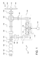
- FIG. 1 there is shown an exemplary embodiment of aspects of wind turbine system 100.
- a rotor 106 includes a plurality of rotor blades 108 coupled to a rotating hub 110, and together define a propeller.
- the propeller is coupled to an optional gear box 118, which is, in turn, coupled to a generator 120.
- generator 120 is a doubly fed induction generator 120 (DFIG).
- DFIG 120 is typically coupled to stator bus 154 and a power conversion component 162 via a rotor bus 156.
- the stator bus 154 provides output of three-phase power from a stator (not separately illustrated) of DFIG 120 and the rotor bus 156 provides output of three-phase power from a rotor (not separately illustrated) of the DFIG 120.
- DFIG 120 is coupled via the rotor bus 156 to a rotor side converter 166.
- the rotor side converter 166 is coupled to a line side converter 168 which in turn is coupled to line side bus 188.
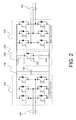
- the rotor side converter 166 and the line side converter 168 are configured for a normal operating mode in a three-phase, two level, Pulse Width Modulation (PWM) arrangement using Insulated Gate Bipolar Transistor (IGBT) switching devices as illustrated in Fig. 2 .
- PWM Pulse Width Modulation
- IGBT Insulated Gate Bipolar Transistor
- the power conversion component 162 also includes a controller 174 to control the operation of the rotor side converter 166 and the line side converter 168. It should be noted that the controller 174, in typical embodiments, is configured as an interface between the power conversion component 162 and a control system 176.
- various line contactors and circuit breakers including, for example, grid breaker 182 may be included to isolate the various components as necessary for normal operation of DFIG 120 during connection to and disconnection from power grid 184.
- a system circuit breaker 178 couples the system bus 160 to transformer 180, which is connected to power grid 184 via grid breaker 182.
- power generated at DFIG 120 by the rotating rotor 106 is provided via a dual path to power grid 184.
- the dual paths are defined by the stator bus 154 and the rotor bus 156.
- sinusoidal three-phase alternating current (AC) power is converted to direct current (DC) power by the power conversion component 162.
- the converted power from the power conversion component 162 is combined with the power from the stator of DFIG 120 to provide three-phase power having a frequency that is maintained substantially constant, for example, at a sixty Hertz AC level.
- the power conversion component 162 compensates or adjusts the frequency of the three-phase power from the rotor of DFIG 120 for changes.
- various circuit breakers and switches within the wind turbine system 100 including grid breaker 182, system breaker 178, stator sync switch 158, converter breaker 186, and line contactor 172 are configured to connect or disconnect corresponding buses, for example, when current flow is excessive and can damage the components of the wind turbine system 100 or for other operational considerations. Additional protection components (not shown) may also be provided.
- wind turbine system 100 may be modified to operate in connection with different power systems, etc. In general, the wind turbine system 100 generates power as is known in the art. It should also be recognized that aspects of wind turbine system 100 as discussed herein are merely illustrative and not limiting thereof.
- the power conversion component 162 receives control signals from, for example, the control system 176 via the controller 174.
- the control signals are based, among other things, on sensed conditions or operating characteristics of the wind turbine system 100.
- the control signals provide for control of the operation of the power conversion component 162.
- feedback in the form of sensed speed of the DFIG 120 may be used to control the conversion of the output power from the rotor bus 156 to maintain a proper and balanced three-phase power supply.
- Other feedback from other sensors also may be used by the control system 174 to control the power conversion component 162, including, for example, stator and rotor bus voltages and current feedbacks.
- switching control signals, stator synchronizing switch control signals and system circuit breaker control (trip) signals may be generated in any known manner.
- both rotor side converter 166 and line side converter 168 correspond, in this exemplary configuration, to a plurality of insulated gate bipolar transistors (IGBTs). It will be appreciated by those of ordinary skill in the art that other types of devices may be used in place of the IGBTs.
- the rotor side converter 166 is configured to receive AC input from rotor bus 156 and to provide a DC voltage across capacitor 138 which is coupled across DC link 136.
- Line side converter 168 is configured to convert the DC voltage on DC link 136 into an AC voltage and to supply such AC voltage to line bus 188.
- dynamic brake 200 may correspond to IGBT 202 coupled in series with dissipative element 204.
- dissipative element 204 may correspond to a resistor of appropriate power handling capacity and IGBT 202 may be controlled using pulse width modulation techniques via controller 206 which is responsive to voltage levels across DC link 136.
- Fig. 3A there is depicted a block diagram of frequency supporting and grid stabilizing current flows in a previously available doubly fed induction generator system (DFIG) system.
- frequency supporting and grid stabilizing currents may flow along the path represented by current path arrow 302 from the rotor of DFIG 300 and join with stator currents represented by current path arrow 304 after passing through rotor side switches 310, DC link 312, and line side switches 314.
- Fig. 3B depicts frequency supporting and grid stabilizing current flows available in accordance with present disclosure.
- previously used line side switches 314 are replaced with higher capacity line side switches 314' corresponding at least in current carrying capacity to that of the rotor side switches 310 as partly represented by the increased font size in Fig. 3B vs. that of Fig. 3A .
- a dynamic brake 316 is provided as previously noted with respect to Fig. 2 coupled across DC link 312. The combination of these features provides for frequency supporting and more grid stabilizing currents as represented by current path arrow 306' from the line side switches 314' and frequency supporting and less grid stabilizing currents from the stator of generator 300 as represented by current path arrow 304'.
- line side converters may be controlled via pulse width modulation techniques to produce a higher or lower voltage than the bus to which they are connected to achieve power factor correction.
- dynamic brake 316 is operated in response to the DC link voltage using, for example, a pulse width modulation technique to control the DC link voltage to provide a generally constant relatively normal level during periods of grid instability.
Landscapes
- Engineering & Computer Science (AREA)
- Power Engineering (AREA)
- Control Of Eletrric Generators (AREA)
- Wind Motors (AREA)
Applications Claiming Priority (1)
| Application Number | Priority Date | Filing Date | Title |
|---|---|---|---|
| US12/915,116 US8093741B2 (en) | 2010-10-29 | 2010-10-29 | Method and system for providing increased turbine output for doubly fed induction generator |
Publications (3)
| Publication Number | Publication Date |
|---|---|
| EP2448079A2 true EP2448079A2 (fr) | 2012-05-02 |
| EP2448079A3 EP2448079A3 (fr) | 2017-06-28 |
| EP2448079B1 EP2448079B1 (fr) | 2019-12-18 |
Family
ID=44142076
Family Applications (1)
| Application Number | Title | Priority Date | Filing Date |
|---|---|---|---|
| EP11185437.8A Active EP2448079B1 (fr) | 2010-10-29 | 2011-10-17 | Procédé et système de fourniture de sortie de turbine améliorée pour générateur d'induction d'alimentation double |
Country Status (4)
| Country | Link |
|---|---|
| US (1) | US8093741B2 (fr) |
| EP (1) | EP2448079B1 (fr) |
| CN (1) | CN102545759B (fr) |
| DK (1) | DK2448079T3 (fr) |
Families Citing this family (42)
| Publication number | Priority date | Publication date | Assignee | Title |
|---|---|---|---|---|
| CA2733100A1 (fr) * | 2009-02-20 | 2010-08-26 | Mitsubishi Heavy Industries, Ltd. | Appareil de generation d'energie eolienne |
| US9494138B2 (en) * | 2009-08-14 | 2016-11-15 | Vestas Wind Systems A/S | Variable speed wind turbine, and a method for operating the variable speed wind turbine during a power imbalance event |
| EP2621071A4 (fr) * | 2010-09-22 | 2017-05-17 | Toshiba Mitsubishi-Electric Industrial Systems Corporation | Dispositif de conversion de puissance |
| DE102011000459B4 (de) * | 2011-02-02 | 2017-11-02 | Universität Kassel | Verfahren zur Lieferung von Blindstrom mit einem Umrichter sowie Umrichteranordnung und Energieversorgungsanlage |
| ITMI20111180A1 (it) * | 2011-06-28 | 2012-12-29 | Wilic Sarl | Impianto eolico per la generazione di energia elettrica |
| US8432055B2 (en) * | 2011-12-12 | 2013-04-30 | General Electric Company | Wind turbine having a high-voltage ride through (HVRT) mode |
| US8907510B2 (en) | 2012-03-09 | 2014-12-09 | General Electric Company | Method and systems for operating a wind turbine |
| DE102012006259A1 (de) * | 2012-03-29 | 2013-10-02 | Repower Systems Se | Chopperverstärkter Umrichter für Windenergieanlagen |
| EP2672624B1 (fr) * | 2012-06-05 | 2014-10-29 | Siemens Aktiengesellschaft | Régulateur de courant et système de générateur |
| CA2878612C (fr) * | 2012-07-12 | 2021-07-27 | General Electric Company | Systeme de freinage dynamique pour un systeme de generation d'electricite et son procede de fonctionnement |
| US8664788B1 (en) * | 2012-09-07 | 2014-03-04 | General Electric Company | Method and systems for operating a wind turbine using dynamic braking in response to a grid event |
| US9030174B2 (en) | 2012-09-14 | 2015-05-12 | General Electric Company | Current balance control in converter for doubly fed induction generator wind turbine system |
| US8791671B2 (en) * | 2012-12-07 | 2014-07-29 | General Electric Company | System and method for optimization of dual bridge doubly fed induction generator (DFIG) |
| US9343991B2 (en) * | 2013-01-18 | 2016-05-17 | General Electric Company | Current balance control for non-interleaved parallel bridge circuits in power converter |
| US9018783B2 (en) * | 2013-05-21 | 2015-04-28 | General Electric Company | Doubly-fed induction generator wind turbine system having solid-state stator switch |
| DK3004637T4 (da) * | 2013-06-04 | 2021-02-15 | Gen Electric | Fremgangsmåder til at drive vindmøllesystem med dynamisk bremse |
| US8975768B2 (en) * | 2013-06-05 | 2015-03-10 | General Electic Company | Methods for operating wind turbine system having dynamic brake |
| US9231509B2 (en) | 2013-11-25 | 2016-01-05 | General Electric Company | System and method for operating a power generation system within a power storage/discharge mode or a dynamic brake mode |
| US9337685B2 (en) | 2013-12-23 | 2016-05-10 | General Electric Company | Optimized filter for battery energy storage on alternate energy systems |
| WO2016015072A1 (fr) * | 2014-07-29 | 2016-02-04 | SIMA, Ewald | Réglage et commande d'un tour électromagnétique mono- ou polyphasé |
| EP3241270B1 (fr) | 2014-12-30 | 2021-06-30 | Vestas Wind Systems A/S | Détermination de tension de référence de liaison cc pour systèmes convertisseurs de turbine éolienne |
| US9705440B2 (en) * | 2015-07-16 | 2017-07-11 | Hamilton Sundstrand Corporation | Fault tolerant electric power generating system |
| AT518007B1 (de) * | 2015-11-27 | 2020-11-15 | Plasser & Theurer Export Von Bahnbaumaschinen Gmbh | Energieversorgungssystem für eine mobile Widerstandsschweißmaschine |
| GB2553872B (en) * | 2016-09-19 | 2018-10-03 | Flexgen Power Systems Inc | Systems and methods for rapid activation of dispatchable power sources |
| US12362566B2 (en) | 2016-09-19 | 2025-07-15 | Flexgen Power Systems, Llc | Systems and methods for rapid activation and synchronization of dispatchable power sources |
| WO2018121821A1 (fr) * | 2016-12-27 | 2018-07-05 | Vestas Wind Systems A/S | Système de commande pour convertisseur multiniveau modulaire |
| US10063172B2 (en) * | 2016-12-27 | 2018-08-28 | General Electric Company | Controlled braking of a generator |
| US10615608B2 (en) * | 2017-04-07 | 2020-04-07 | General Electric Company | Low-wind operation of clustered doubly fed induction generator wind turbines |
| US10103663B1 (en) * | 2017-04-18 | 2018-10-16 | General Electric Company | Control method for protecting switching devices in power converters in doubly fed induction generator power systems |
| US10784685B2 (en) * | 2017-05-08 | 2020-09-22 | General Electric Company | Electrical power systems and subsystems |
| US10790770B2 (en) * | 2017-05-25 | 2020-09-29 | General Electric Company | Methods for operating electrical power systems |
| US10630215B2 (en) | 2017-11-20 | 2020-04-21 | General Electric Company | System and method for operating a doubly fed induction generator system to reduce harmonics |
| CN110080944B (zh) * | 2018-01-26 | 2021-09-24 | 通用电气公司 | 风力发电系统及其控制方法 |
| GB201803977D0 (en) * | 2018-03-13 | 2018-04-25 | Rolls Royce Plc | Fault ride-through system |
| US10615727B2 (en) * | 2018-08-27 | 2020-04-07 | General Electric Company | Dynamic brake circuit assembly for a wind turbine |
| US10826297B2 (en) * | 2018-11-06 | 2020-11-03 | General Electric Company | System and method for wind power generation and transmission in electrical power systems |
| US10742149B1 (en) * | 2019-04-22 | 2020-08-11 | General Electric Company | System and method for reactive power control of a wind turbine by varying switching frequency of rotor side converter |
| US10731628B1 (en) * | 2019-05-06 | 2020-08-04 | General Electric Company | System and method for coordinated control of reactive power from a generator and a reactive power compensation device in a wind turbine system |
| EP3872979A1 (fr) * | 2020-02-26 | 2021-09-01 | Siemens Gamesa Renewable Energy Innovation & Technology, S.L. | Commande d'un générateur d'induction d'une éolienne |
| US11486360B2 (en) | 2020-04-10 | 2022-11-01 | General Electric Company | System and method for controlling wind turbine converters during high voltage ride through events |
| US11005401B1 (en) | 2020-06-19 | 2021-05-11 | General Electric Company | Methods for operating an inverter-based resource connected to a series-compensated transmission system |
| CN113431641A (zh) * | 2021-06-29 | 2021-09-24 | 西安热工研究院有限公司 | 一种能够同时输出多种频率电流的发电机系统 |
Family Cites Families (17)
| Publication number | Priority date | Publication date | Assignee | Title |
|---|---|---|---|---|
| EP1625457A4 (fr) * | 2003-05-02 | 2015-04-22 | Xantrex Technology Inc | Systeme de commande de generateur d'induction a double alimentation |
| US7239036B2 (en) * | 2005-07-29 | 2007-07-03 | General Electric Company | System and method for power control in wind turbines |
| US7372174B2 (en) * | 2005-11-11 | 2008-05-13 | Converteam Ltd | Power converters |
| US7345373B2 (en) * | 2005-11-29 | 2008-03-18 | General Electric Company | System and method for utility and wind turbine control |
| US7423412B2 (en) * | 2006-01-31 | 2008-09-09 | General Electric Company | Method, apparatus and computer program product for injecting current |
| CN101401294B (zh) * | 2006-03-17 | 2013-04-17 | 英捷电力技术有限公司 | 具有激励器设备和不连接至电网的功率变换器的变速风机 |
| US7425771B2 (en) * | 2006-03-17 | 2008-09-16 | Ingeteam S.A. | Variable speed wind turbine having an exciter machine and a power converter not connected to the grid |
| EP2032846A4 (fr) * | 2006-05-31 | 2011-04-13 | Wisconsin Alumni Res Found | Architecture de conditionnement de l'énergie pour une éolienne |
| US7586216B2 (en) * | 2006-06-02 | 2009-09-08 | General Electric Company | Redundant electrical brake and protection system for electric generators |
| US7573732B2 (en) * | 2007-05-25 | 2009-08-11 | General Electric Company | Protective circuit and method for multi-level converter |
| KR100886194B1 (ko) * | 2007-06-08 | 2009-02-27 | 한국전기연구원 | 계통 연계형 고압 권선형 유도 발전기 제어 장치 |
| US8004252B2 (en) * | 2007-06-29 | 2011-08-23 | General Electric Company | Power system stabilizer and method |
| US8237301B2 (en) * | 2008-01-31 | 2012-08-07 | General Electric Company | Power generation stabilization control systems and methods |
| DE102008017715A1 (de) * | 2008-04-02 | 2009-10-15 | Nordex Energy Gmbh | Verfahren zum Betreiben einer Windenergieanlage mit einer doppelt gespeisten Asynchronmaschine sowie Windenergieanlage mit einer doppelt gespeisten Asynchronmaschine |
| CN101383578A (zh) * | 2008-09-22 | 2009-03-11 | 艾默生网络能源有限公司 | 一种具有保护装置的双馈发电机系统及其保护方法 |
| CN101383580B (zh) * | 2008-10-22 | 2011-04-06 | 重庆大学 | 电网短路故障时的双馈感应风力发电机低电压穿越控制方法 |
| US7978445B2 (en) * | 2009-12-31 | 2011-07-12 | General Electric Company | Systems and apparatus relating to wind turbine electrical control and operation |
-
2010
- 2010-10-29 US US12/915,116 patent/US8093741B2/en active Active
-
2011
- 2011-10-17 DK DK11185437.8T patent/DK2448079T3/da active
- 2011-10-17 EP EP11185437.8A patent/EP2448079B1/fr active Active
- 2011-10-28 CN CN201110346429.2A patent/CN102545759B/zh active Active
Non-Patent Citations (1)
| Title |
|---|
| None |
Also Published As
| Publication number | Publication date |
|---|---|
| US8093741B2 (en) | 2012-01-10 |
| EP2448079A3 (fr) | 2017-06-28 |
| US20110140430A1 (en) | 2011-06-16 |
| CN102545759B (zh) | 2015-02-11 |
| EP2448079B1 (fr) | 2019-12-18 |
| DK2448079T3 (da) | 2020-03-23 |
| CN102545759A (zh) | 2012-07-04 |
Similar Documents
| Publication | Publication Date | Title |
|---|---|---|
| EP2448079B1 (fr) | Procédé et système de fourniture de sortie de turbine améliorée pour générateur d'induction d'alimentation double | |
| US7239036B2 (en) | System and method for power control in wind turbines | |
| CA2826437C (fr) | Commande de tension dans une eolienne generatrice a induction a double alimentation | |
| US9366233B2 (en) | Method and arrangement for controlling an operation of an electric energy production facility during a disconnection to a utility grid | |
| US8519568B2 (en) | Inrush current protection for wind turbines and wind farms | |
| US7843078B2 (en) | Method and apparatus for generating power in a wind turbine | |
| CN111828251B (zh) | 用于风力涡轮的无功功率控制的系统和方法 | |
| EP2725701B1 (fr) | Commande d'équilibrage de courant dans un convertisseur pour système de turbine éolienne avec générateur d'induction à alimentation double | |
| EP3736938A1 (fr) | Procédé d'amortissement de l'oscillation de puissance réactive pour un système d'éolienne doté d'un dispositif de compensation de puissance réactive intégré | |
| EP3736935B1 (fr) | Système d'éolienne doté d'un dispositif de compensation de puissance réactive intégré | |
| EP3893383A1 (fr) | Système et procédé de contrôle de convertisseurs d'éolienne pendant le temps de maintien d'alimentation en cas d'événements de haute tension | |
| CA2835303C (fr) | Systeme et methode d'optimisation de generateur a induction a double alimentation a double pont | |
| WO2025141303A1 (fr) | Système et procédé pour assurer un démarrage à froid de ressources basées sur un onduleur formant un réseau | |
| WO2025155283A1 (fr) | Système et procédé pour réaliser un démarrage autonome de ressources basées sur un onduleur formant un réseau | |
| WO2025063949A1 (fr) | Système et procédé pour fournir des services de démarrage noir à partir de ressources basées sur des onduleurs |
Legal Events
| Date | Code | Title | Description |
|---|---|---|---|
| PUAI | Public reference made under article 153(3) epc to a published international application that has entered the european phase |
Free format text: ORIGINAL CODE: 0009012 |
|
| AK | Designated contracting states |
Kind code of ref document: A2 Designated state(s): AL AT BE BG CH CY CZ DE DK EE ES FI FR GB GR HR HU IE IS IT LI LT LU LV MC MK MT NL NO PL PT RO RS SE SI SK SM TR |
|
| AX | Request for extension of the european patent |
Extension state: BA ME |
|
| PUAL | Search report despatched |
Free format text: ORIGINAL CODE: 0009013 |
|
| AK | Designated contracting states |
Kind code of ref document: A3 Designated state(s): AL AT BE BG CH CY CZ DE DK EE ES FI FR GB GR HR HU IE IS IT LI LT LU LV MC MK MT NL NO PL PT RO RS SE SI SK SM TR |
|
| AX | Request for extension of the european patent |
Extension state: BA ME |
|
| RIC1 | Information provided on ipc code assigned before grant |
Ipc: H02P 3/22 20060101ALI20170524BHEP Ipc: H02J 3/38 20060101AFI20170524BHEP Ipc: H02P 9/00 20060101ALI20170524BHEP |
|
| STAA | Information on the status of an ep patent application or granted ep patent |
Free format text: STATUS: REQUEST FOR EXAMINATION WAS MADE |
|
| 17P | Request for examination filed |
Effective date: 20180102 |
|
| RBV | Designated contracting states (corrected) |
Designated state(s): AL AT BE BG CH CY CZ DE DK EE ES FI FR GB GR HR HU IE IS IT LI LT LU LV MC MK MT NL NO PL PT RO RS SE SI SK SM TR |
|
| REG | Reference to a national code |
Ref country code: DE Ref legal event code: R079 Ref document number: 602011064063 Country of ref document: DE Free format text: PREVIOUS MAIN CLASS: H02J0003380000 Ipc: H02P0009100000 |
|
| GRAP | Despatch of communication of intention to grant a patent |
Free format text: ORIGINAL CODE: EPIDOSNIGR1 |
|
| STAA | Information on the status of an ep patent application or granted ep patent |
Free format text: STATUS: GRANT OF PATENT IS INTENDED |
|
| RIC1 | Information provided on ipc code assigned before grant |
Ipc: H02P 9/10 20060101AFI20190118BHEP Ipc: H02J 3/38 20060101ALI20190118BHEP Ipc: H02P 3/22 20060101ALI20190118BHEP Ipc: H02P 9/00 20060101ALI20190118BHEP |
|
| INTG | Intention to grant announced |
Effective date: 20190214 |
|
| RIN1 | Information on inventor provided before grant (corrected) |
Inventor name: MELIUS, JEFFREY ALAN Inventor name: RITTER, ALLEN MICHAEL |
|
| GRAJ | Information related to disapproval of communication of intention to grant by the applicant or resumption of examination proceedings by the epo deleted |
Free format text: ORIGINAL CODE: EPIDOSDIGR1 |
|
| STAA | Information on the status of an ep patent application or granted ep patent |
Free format text: STATUS: REQUEST FOR EXAMINATION WAS MADE |
|
| GRAP | Despatch of communication of intention to grant a patent |
Free format text: ORIGINAL CODE: EPIDOSNIGR1 |
|
| STAA | Information on the status of an ep patent application or granted ep patent |
Free format text: STATUS: GRANT OF PATENT IS INTENDED |
|
| INTC | Intention to grant announced (deleted) | ||
| INTG | Intention to grant announced |
Effective date: 20190710 |
|
| GRAS | Grant fee paid |
Free format text: ORIGINAL CODE: EPIDOSNIGR3 |
|
| GRAA | (expected) grant |
Free format text: ORIGINAL CODE: 0009210 |
|
| STAA | Information on the status of an ep patent application or granted ep patent |
Free format text: STATUS: THE PATENT HAS BEEN GRANTED |
|
| AK | Designated contracting states |
Kind code of ref document: B1 Designated state(s): AL AT BE BG CH CY CZ DE DK EE ES FI FR GB GR HR HU IE IS IT LI LT LU LV MC MK MT NL NO PL PT RO RS SE SI SK SM TR |
|
| REG | Reference to a national code |
Ref country code: GB Ref legal event code: FG4D |
|
| REG | Reference to a national code |
Ref country code: CH Ref legal event code: EP |
|
| REG | Reference to a national code |
Ref country code: IE Ref legal event code: FG4D |
|
| REG | Reference to a national code |
Ref country code: DE Ref legal event code: R096 Ref document number: 602011064063 Country of ref document: DE |
|
| REG | Reference to a national code |
Ref country code: AT Ref legal event code: REF Ref document number: 1215675 Country of ref document: AT Kind code of ref document: T Effective date: 20200115 |
|
| REG | Reference to a national code |
Ref country code: DK Ref legal event code: T3 Effective date: 20200318 |
|
| REG | Reference to a national code |
Ref country code: NL Ref legal event code: MP Effective date: 20191218 |
|
| PG25 | Lapsed in a contracting state [announced via postgrant information from national office to epo] |
Ref country code: FI Free format text: LAPSE BECAUSE OF FAILURE TO SUBMIT A TRANSLATION OF THE DESCRIPTION OR TO PAY THE FEE WITHIN THE PRESCRIBED TIME-LIMIT Effective date: 20191218 Ref country code: NO Free format text: LAPSE BECAUSE OF FAILURE TO SUBMIT A TRANSLATION OF THE DESCRIPTION OR TO PAY THE FEE WITHIN THE PRESCRIBED TIME-LIMIT Effective date: 20200318 Ref country code: GR Free format text: LAPSE BECAUSE OF FAILURE TO SUBMIT A TRANSLATION OF THE DESCRIPTION OR TO PAY THE FEE WITHIN THE PRESCRIBED TIME-LIMIT Effective date: 20200319 Ref country code: LT Free format text: LAPSE BECAUSE OF FAILURE TO SUBMIT A TRANSLATION OF THE DESCRIPTION OR TO PAY THE FEE WITHIN THE PRESCRIBED TIME-LIMIT Effective date: 20191218 Ref country code: LV Free format text: LAPSE BECAUSE OF FAILURE TO SUBMIT A TRANSLATION OF THE DESCRIPTION OR TO PAY THE FEE WITHIN THE PRESCRIBED TIME-LIMIT Effective date: 20191218 Ref country code: BG Free format text: LAPSE BECAUSE OF FAILURE TO SUBMIT A TRANSLATION OF THE DESCRIPTION OR TO PAY THE FEE WITHIN THE PRESCRIBED TIME-LIMIT Effective date: 20200318 Ref country code: SE Free format text: LAPSE BECAUSE OF FAILURE TO SUBMIT A TRANSLATION OF THE DESCRIPTION OR TO PAY THE FEE WITHIN THE PRESCRIBED TIME-LIMIT Effective date: 20191218 |
|
| REG | Reference to a national code |
Ref country code: LT Ref legal event code: MG4D |
|
| PG25 | Lapsed in a contracting state [announced via postgrant information from national office to epo] |
Ref country code: RS Free format text: LAPSE BECAUSE OF FAILURE TO SUBMIT A TRANSLATION OF THE DESCRIPTION OR TO PAY THE FEE WITHIN THE PRESCRIBED TIME-LIMIT Effective date: 20191218 Ref country code: HR Free format text: LAPSE BECAUSE OF FAILURE TO SUBMIT A TRANSLATION OF THE DESCRIPTION OR TO PAY THE FEE WITHIN THE PRESCRIBED TIME-LIMIT Effective date: 20191218 |
|
| PG25 | Lapsed in a contracting state [announced via postgrant information from national office to epo] |
Ref country code: AL Free format text: LAPSE BECAUSE OF FAILURE TO SUBMIT A TRANSLATION OF THE DESCRIPTION OR TO PAY THE FEE WITHIN THE PRESCRIBED TIME-LIMIT Effective date: 20191218 |
|
| PG25 | Lapsed in a contracting state [announced via postgrant information from national office to epo] |
Ref country code: NL Free format text: LAPSE BECAUSE OF FAILURE TO SUBMIT A TRANSLATION OF THE DESCRIPTION OR TO PAY THE FEE WITHIN THE PRESCRIBED TIME-LIMIT Effective date: 20191218 Ref country code: RO Free format text: LAPSE BECAUSE OF FAILURE TO SUBMIT A TRANSLATION OF THE DESCRIPTION OR TO PAY THE FEE WITHIN THE PRESCRIBED TIME-LIMIT Effective date: 20191218 Ref country code: CZ Free format text: LAPSE BECAUSE OF FAILURE TO SUBMIT A TRANSLATION OF THE DESCRIPTION OR TO PAY THE FEE WITHIN THE PRESCRIBED TIME-LIMIT Effective date: 20191218 Ref country code: PT Free format text: LAPSE BECAUSE OF FAILURE TO SUBMIT A TRANSLATION OF THE DESCRIPTION OR TO PAY THE FEE WITHIN THE PRESCRIBED TIME-LIMIT Effective date: 20200513 Ref country code: EE Free format text: LAPSE BECAUSE OF FAILURE TO SUBMIT A TRANSLATION OF THE DESCRIPTION OR TO PAY THE FEE WITHIN THE PRESCRIBED TIME-LIMIT Effective date: 20191218 |
|
| PG25 | Lapsed in a contracting state [announced via postgrant information from national office to epo] |
Ref country code: SK Free format text: LAPSE BECAUSE OF FAILURE TO SUBMIT A TRANSLATION OF THE DESCRIPTION OR TO PAY THE FEE WITHIN THE PRESCRIBED TIME-LIMIT Effective date: 20191218 Ref country code: IS Free format text: LAPSE BECAUSE OF FAILURE TO SUBMIT A TRANSLATION OF THE DESCRIPTION OR TO PAY THE FEE WITHIN THE PRESCRIBED TIME-LIMIT Effective date: 20200418 Ref country code: SM Free format text: LAPSE BECAUSE OF FAILURE TO SUBMIT A TRANSLATION OF THE DESCRIPTION OR TO PAY THE FEE WITHIN THE PRESCRIBED TIME-LIMIT Effective date: 20191218 |
|
| REG | Reference to a national code |
Ref country code: DE Ref legal event code: R097 Ref document number: 602011064063 Country of ref document: DE |
|
| REG | Reference to a national code |
Ref country code: AT Ref legal event code: MK05 Ref document number: 1215675 Country of ref document: AT Kind code of ref document: T Effective date: 20191218 |
|
| PLBE | No opposition filed within time limit |
Free format text: ORIGINAL CODE: 0009261 |
|
| STAA | Information on the status of an ep patent application or granted ep patent |
Free format text: STATUS: NO OPPOSITION FILED WITHIN TIME LIMIT |
|
| PG25 | Lapsed in a contracting state [announced via postgrant information from national office to epo] |
Ref country code: ES Free format text: LAPSE BECAUSE OF FAILURE TO SUBMIT A TRANSLATION OF THE DESCRIPTION OR TO PAY THE FEE WITHIN THE PRESCRIBED TIME-LIMIT Effective date: 20191218 |
|
| 26N | No opposition filed |
Effective date: 20200921 |
|
| PG25 | Lapsed in a contracting state [announced via postgrant information from national office to epo] |
Ref country code: SI Free format text: LAPSE BECAUSE OF FAILURE TO SUBMIT A TRANSLATION OF THE DESCRIPTION OR TO PAY THE FEE WITHIN THE PRESCRIBED TIME-LIMIT Effective date: 20191218 Ref country code: AT Free format text: LAPSE BECAUSE OF FAILURE TO SUBMIT A TRANSLATION OF THE DESCRIPTION OR TO PAY THE FEE WITHIN THE PRESCRIBED TIME-LIMIT Effective date: 20191218 |
|
| PG25 | Lapsed in a contracting state [announced via postgrant information from national office to epo] |
Ref country code: IT Free format text: LAPSE BECAUSE OF FAILURE TO SUBMIT A TRANSLATION OF THE DESCRIPTION OR TO PAY THE FEE WITHIN THE PRESCRIBED TIME-LIMIT Effective date: 20191218 |
|
| PG25 | Lapsed in a contracting state [announced via postgrant information from national office to epo] |
Ref country code: PL Free format text: LAPSE BECAUSE OF FAILURE TO SUBMIT A TRANSLATION OF THE DESCRIPTION OR TO PAY THE FEE WITHIN THE PRESCRIBED TIME-LIMIT Effective date: 20191218 |
|
| REG | Reference to a national code |
Ref country code: CH Ref legal event code: PL |
|
| GBPC | Gb: european patent ceased through non-payment of renewal fee |
Effective date: 20201017 |
|
| PG25 | Lapsed in a contracting state [announced via postgrant information from national office to epo] |
Ref country code: MC Free format text: LAPSE BECAUSE OF FAILURE TO SUBMIT A TRANSLATION OF THE DESCRIPTION OR TO PAY THE FEE WITHIN THE PRESCRIBED TIME-LIMIT Effective date: 20191218 Ref country code: LU Free format text: LAPSE BECAUSE OF NON-PAYMENT OF DUE FEES Effective date: 20201017 |
|
| REG | Reference to a national code |
Ref country code: BE Ref legal event code: MM Effective date: 20201031 |
|
| PG25 | Lapsed in a contracting state [announced via postgrant information from national office to epo] |
Ref country code: FR Free format text: LAPSE BECAUSE OF NON-PAYMENT OF DUE FEES Effective date: 20201031 |
|
| PG25 | Lapsed in a contracting state [announced via postgrant information from national office to epo] |
Ref country code: GB Free format text: LAPSE BECAUSE OF NON-PAYMENT OF DUE FEES Effective date: 20201017 Ref country code: LI Free format text: LAPSE BECAUSE OF NON-PAYMENT OF DUE FEES Effective date: 20201031 Ref country code: CH Free format text: LAPSE BECAUSE OF NON-PAYMENT OF DUE FEES Effective date: 20201031 Ref country code: BE Free format text: LAPSE BECAUSE OF NON-PAYMENT OF DUE FEES Effective date: 20201031 |
|
| PG25 | Lapsed in a contracting state [announced via postgrant information from national office to epo] |
Ref country code: IE Free format text: LAPSE BECAUSE OF NON-PAYMENT OF DUE FEES Effective date: 20201017 |
|
| PG25 | Lapsed in a contracting state [announced via postgrant information from national office to epo] |
Ref country code: TR Free format text: LAPSE BECAUSE OF FAILURE TO SUBMIT A TRANSLATION OF THE DESCRIPTION OR TO PAY THE FEE WITHIN THE PRESCRIBED TIME-LIMIT Effective date: 20191218 Ref country code: MT Free format text: LAPSE BECAUSE OF FAILURE TO SUBMIT A TRANSLATION OF THE DESCRIPTION OR TO PAY THE FEE WITHIN THE PRESCRIBED TIME-LIMIT Effective date: 20191218 Ref country code: CY Free format text: LAPSE BECAUSE OF FAILURE TO SUBMIT A TRANSLATION OF THE DESCRIPTION OR TO PAY THE FEE WITHIN THE PRESCRIBED TIME-LIMIT Effective date: 20191218 |
|
| PG25 | Lapsed in a contracting state [announced via postgrant information from national office to epo] |
Ref country code: MK Free format text: LAPSE BECAUSE OF FAILURE TO SUBMIT A TRANSLATION OF THE DESCRIPTION OR TO PAY THE FEE WITHIN THE PRESCRIBED TIME-LIMIT Effective date: 20191218 |
|
| P01 | Opt-out of the competence of the unified patent court (upc) registered |
Effective date: 20230530 |
|
| REG | Reference to a national code |
Ref country code: DE Ref legal event code: R082 Ref document number: 602011064063 Country of ref document: DE Representative=s name: ZIMMERMANN & PARTNER PATENTANWAELTE MBB, DE Ref country code: DE Ref legal event code: R082 Ref document number: 602011064063 Country of ref document: DE Ref country code: DE Ref legal event code: R081 Ref document number: 602011064063 Country of ref document: DE Owner name: GENERAL ELECTRIC RENOVABLES ESPANA, S.L., ES Free format text: FORMER OWNER: GENERAL ELECTRIC COMPANY, SCHENECTADY, NY, US |
|
| REG | Reference to a national code |
Ref country code: DE Ref legal event code: R082 Ref document number: 602011064063 Country of ref document: DE Representative=s name: ZIMMERMANN & PARTNER PATENTANWAELTE MBB, DE |
|
| PGFP | Annual fee paid to national office [announced via postgrant information from national office to epo] |
Ref country code: DK Payment date: 20250923 Year of fee payment: 15 |
|
| PGFP | Annual fee paid to national office [announced via postgrant information from national office to epo] |
Ref country code: DE Payment date: 20250923 Year of fee payment: 15 |