EP2448080A2 - Système de contrôle de convertisseur - Google Patents
Système de contrôle de convertisseur Download PDFInfo
- Publication number
- EP2448080A2 EP2448080A2 EP11007123A EP11007123A EP2448080A2 EP 2448080 A2 EP2448080 A2 EP 2448080A2 EP 11007123 A EP11007123 A EP 11007123A EP 11007123 A EP11007123 A EP 11007123A EP 2448080 A2 EP2448080 A2 EP 2448080A2
- Authority
- EP
- European Patent Office
- Prior art keywords
- converter
- modules
- control system
- enabled
- grid
- Prior art date
- Legal status (The legal status is an assumption and is not a legal conclusion. Google has not performed a legal analysis and makes no representation as to the accuracy of the status listed.)
- Granted
Links
Images


Classifications
-
- H—ELECTRICITY
- H02—GENERATION; CONVERSION OR DISTRIBUTION OF ELECTRIC POWER
- H02J—ELECTRIC POWER NETWORKS; CIRCUIT ARRANGEMENTS OR SYSTEMS FOR SUPPLYING OR DISTRIBUTING ELECTRIC POWER; SYSTEMS FOR STORING ELECTRIC ENERGY
- H02J3/00—Circuit arrangements for AC mains or AC distribution networks
- H02J3/38—Arrangements for feeding a single network from two or more generators or sources in parallel; Arrangements for feeding already energised networks from additional generators or sources in parallel
- H02J3/46—Controlling the sharing of generated power between the generators, sources or networks
- H02J3/50—Controlling the sharing of reactive power
-
- H—ELECTRICITY
- H02—GENERATION; CONVERSION OR DISTRIBUTION OF ELECTRIC POWER
- H02J—ELECTRIC POWER NETWORKS; CIRCUIT ARRANGEMENTS OR SYSTEMS FOR SUPPLYING OR DISTRIBUTING ELECTRIC POWER; SYSTEMS FOR STORING ELECTRIC ENERGY
- H02J3/00—Circuit arrangements for AC mains or AC distribution networks
- H02J3/38—Arrangements for feeding a single network from two or more generators or sources in parallel; Arrangements for feeding already energised networks from additional generators or sources in parallel
- H02J3/381—Dispersed generators
-
- H—ELECTRICITY
- H02—GENERATION; CONVERSION OR DISTRIBUTION OF ELECTRIC POWER
- H02J—ELECTRIC POWER NETWORKS; CIRCUIT ARRANGEMENTS OR SYSTEMS FOR SUPPLYING OR DISTRIBUTING ELECTRIC POWER; SYSTEMS FOR STORING ELECTRIC ENERGY
- H02J3/00—Circuit arrangements for AC mains or AC distribution networks
- H02J3/38—Arrangements for feeding a single network from two or more generators or sources in parallel; Arrangements for feeding already energised networks from additional generators or sources in parallel
- H02J3/46—Controlling the sharing of generated power between the generators, sources or networks
-
- H—ELECTRICITY
- H02—GENERATION; CONVERSION OR DISTRIBUTION OF ELECTRIC POWER
- H02J—ELECTRIC POWER NETWORKS; CIRCUIT ARRANGEMENTS OR SYSTEMS FOR SUPPLYING OR DISTRIBUTING ELECTRIC POWER; SYSTEMS FOR STORING ELECTRIC ENERGY
- H02J2101/00—Supply or distribution of decentralised, dispersed or local electric power generation
- H02J2101/20—Dispersed power generation using renewable energy sources
- H02J2101/28—Wind energy
-
- Y—GENERAL TAGGING OF NEW TECHNOLOGICAL DEVELOPMENTS; GENERAL TAGGING OF CROSS-SECTIONAL TECHNOLOGIES SPANNING OVER SEVERAL SECTIONS OF THE IPC; TECHNICAL SUBJECTS COVERED BY FORMER USPC CROSS-REFERENCE ART COLLECTIONS [XRACs] AND DIGESTS
- Y02—TECHNOLOGIES OR APPLICATIONS FOR MITIGATION OR ADAPTATION AGAINST CLIMATE CHANGE
- Y02E—REDUCTION OF GREENHOUSE GAS [GHG] EMISSIONS, RELATED TO ENERGY GENERATION, TRANSMISSION OR DISTRIBUTION
- Y02E10/00—Energy generation through renewable energy sources
- Y02E10/70—Wind energy
- Y02E10/76—Power conversion electric or electronic aspects
Definitions
- the object of the invention is related to the field of electric power generation by a wind turbine connected to a utility grid, and specifically to wind turbines and electric power conversion systems that include converter modules for delivering electric power to the utility grid.
- Wind turbines with variable rotor speed are connected to the utility grid through a power converter that converts the alternating current produced in a generator (which as a general rule is coupled to the blades through a gearbox) to direct current with adjustable frequency and amplitude.
- a generator which as a general rule is coupled to the blades through a gearbox
- converters comprising various modules interconnected in parallel, which allow greater controllability of power delivery in the grid.
- the components in these converter modules are oversized; because such maximum power can only be delivered to the grid on very isolated occasions, optimization of the various modules is needed in order to ensure proper management of each operating point in the converter.
- Another control strategy is the one described by this applicant in European Patent EP1768223 , which proposes a method for using a wind turbine converter system, including converter modules connected in parallel and capable of converting the electric power produced by a generator to electric power applicable to a utility grid.
- the method determines the enabling/disabling of the converter modules in response to parameters related to the variable amount of electric power being produced by the generator, such as, for example, temperature of the converter module's components, reference apparent power and reference active power for the converter system, a current reference to the converter system, a measured value of the apparent power produced by the generator or the apparent power delivered to the grid, a measured value of the active power produced by the generator or the active power delivered to the grid, and a measured value of the current produced by the generator or the current delivered to the grid.
- the State of the Art also envisages the possibility of disconnecting modules for a short or extended period of time and proposes the enabling/disabling of the converter modules by means of pulse-width modulation (PWM) patterns, in such a way that two or more converters are out of phase in relation to each other, thus reducing the harmonic components arriving from PWM and, therefore, improving the quality of the voltage signal applied to the utility grid.
- PWM pulse-width modulation
- this solution has one disadvantage: whenever it is necessary to vary the number of converters connected and, therefore, the switching phase difference set by the PWM patterns, such switching needs to be stopped, the different modules have to be reconfigured with the new phase difference, and they must then be reconnected. In other words, delivery of electric power to the grid needs to be stopped, since enabling or disabling a new converter module causes current peaks that set off the overcurrent alarms, and the wind turbine would enter emergency stop mode. These stops cause substantial production losses.
- This invention proposes a control system for a wind turbine converter which includes at least two converter modules connected in parallel and capable of converting the electric power produced by a generator to electric power applicable to a utility grid, and allows the number of enabled converters to be increased or decreased based on the wind speed.
- Another object of the invention is to provide a control method which, through synchronized PWM connection of converter modules, guarantees the minimum level of harmonics in the distribution grid.
- Another object of the invention is to guarantee dynamic switching between converter modules during delivery of electric power to the distribution grid, without the overcurrent protections going off and without voltage peaks being caused by connection or disconnection of different modules depending on the grid's needs.
- the invention comprises a control system connected to the converter and to the wind turbine generator.
- the control system calculates the number of converters that need to be connected to obtain a given power, based on the wind speed and a number of preset power parameters, in order to guarantee maximum converter efficiency and reliability.
- the control system reconfigures the enabled control modules by changing their switching offsets (phase differences) in a gradual an continuous manner, guaranteeing that no current peaks appear in the distribution grid.
- Figure 1 shows a converter (1) that comprises at least two conventional converter modules (2) connected in parallel and which is connected to a wind turbine generator (3), a transformer (4) that connects the signal of the converter system (1) to the utility grid (5) and a circuit breaker (6).
- Each converter module (2) In the converter (1) Includes a generator contactor (kgen) for disconnecting the generator (3) from the electronic mechanisms of the converter module (2), an inductor (2.1) to smooth out the generator's current, a generator inverter (2.2) to convert the AC signal of the generator (3) to a DC signal, a DC bus condenser (2.3) to filter the variations in the DC signal, a chopper brake (2.4) to dissipate the residual voltage, a grid-side inverter (2.5) to convert the DC signal to an AC signal, and an inductor (2.6) which, combined with condensers, reduces the harmonics in the voltage signal applied to the utility grid (5).
- the converter module (2) also includes a grid contactor (kgrid) for disconnecting the utility grid (5) from the electronics of the converter module (2) and a circuit breaker (2.8) for disconnecting the utility grid (5) from the converter module (2) in the event of an overvoltage or overcurrent condition.
- a grid contactor (kgrid) for disconnecting the utility grid (5) from the electronics of the converter module (2)
- a circuit breaker (2.8) for disconnecting the utility grid (5) from the converter module (2) in the event of an overvoltage or overcurrent condition.
- the converter (1) is connected to a control system (7) which in turn is connected to the wind turbine's generator (3), and which guarantees efficient operation of the converter (1) and the quality of the voltage signal that is applied to the utility grid (5).
- the converter modules (2) Before the converter modules (2) can supply electric power to the utility grid (5), they need to be enabled by transitioning from an initial disconnection state to a final, fully operational state which is controlled through said control system (7).
- the generator-side inverter (2.2) and the grid-side inverter (2.5) of each converter module (2) are enabled by applying electric enabling signals, as voltage signals with pulse-width modulation (PWM), and are disabled by applying electric disabling signals, as zero-voltage signals, to the transistor gate of the generator-side inverter (2.2) and of the grid-side inverter (2.5); these are IGBT-type transistors.
- PWM pulse-width modulation
- the duration of the converter module (2) transition from the run-state to the off-state, or the duration of the opposite transition, from the off-state to the run-state, can be set between 1 and 10 seconds.
- the control system (7) calculates a dynamic switching current I DS based on the difference between the current to be produced I producible and the converter's real current I conv_real (which is the sum of all the real currents of the various converter modules). Interpolation between said dynamic switching current I DS and a table of parameters related to the wind speed will determine the number of converters that need to be enabled.
- the control system (7) has at least one enabling sequence that determines the order in which the converter modules (2) will be enabled and/or disabled. Moreover, if according to the preset enabling sequence it is necessary to enable the next converter module (2) and it is not ready, the control system (7) will enable the next converter module (2) according to that enabling sequence.
- control system (7) of the invention switches the grid-side inverter (2.3) based on pulse-width modulation (PWM), through which the harmonics generated by the PWM technique are reduced, thus guaranteeing that the pulse-width modulation (PWM) patterns of two or more converter modules (2) are out of phase in relation to each other.
- PWM pulse-width modulation
- the control system (7) dynamically regulates the switch from phase difference X, for a given number of enabled converter modules (2), to another phase difference Y, in relation to a higher or lower number of connected converter modules (2); to do so, before enabling or disabling the corresponding converter module, it gradually increases or decreases the phase difference existing between the connected converter modules, thus guaranteeing ongoing switching during this gradual phase difference variation and avoiding having to stop delivering power to the utility grid (5), as well as preventing the appearance of current peaks that can give rise to an alarm and cause the wind turbine to stop.
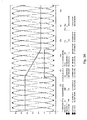
- Figures 2A and 2B show the grid current signal, with and without the control system respectively, for an offset variation (phase difference) of 90° to 180°, i.e., for a variation of 4 to 2 converter modules.
- phase difference phase difference
- Figure 28 shows the current signal delivered to the grid by a converter equipped with the control system of the invention; no current peaks are seen in said current signal.
- control system (7) checks the real amount of electric power produced by the generator (3) and, based on a number of preset power parameters related to the existing wind speed, determines (7.1) the number of converter modules (2) that need to be enabled, setting (7.2) in turn the pulse-width modulation (PWM) phase difference pattern between the converter modules (2) that need to be enabled and gradually varying (7.3), by means of a ramped signal, the phase differences between the enabled converter modules (2) until the phase difference of the modulation pattern determined in the calculations made is reached (see Figures 3A and 3B ).
- PWM pulse-width modulation
Landscapes
- Engineering & Computer Science (AREA)
- Power Engineering (AREA)
- Control Of Eletrric Generators (AREA)
- Wind Motors (AREA)
Applications Claiming Priority (1)
| Application Number | Priority Date | Filing Date | Title |
|---|---|---|---|
| ES201001164A ES2398174B1 (es) | 2010-09-09 | 2010-09-09 | Sistema de control de un convertidor. |
Publications (3)
| Publication Number | Publication Date |
|---|---|
| EP2448080A2 true EP2448080A2 (fr) | 2012-05-02 |
| EP2448080A3 EP2448080A3 (fr) | 2016-08-31 |
| EP2448080B1 EP2448080B1 (fr) | 2019-05-08 |
Family
ID=44785098
Family Applications (1)
| Application Number | Title | Priority Date | Filing Date |
|---|---|---|---|
| EP11007123.0A Active EP2448080B1 (fr) | 2010-09-09 | 2011-09-02 | Système de contrôle de convertisseur |
Country Status (4)
| Country | Link |
|---|---|
| US (1) | US8923023B2 (fr) |
| EP (1) | EP2448080B1 (fr) |
| CN (1) | CN102403729B (fr) |
| ES (2) | ES2398174B1 (fr) |
Families Citing this family (4)
| Publication number | Priority date | Publication date | Assignee | Title |
|---|---|---|---|---|
| EP2775446A1 (fr) * | 2013-03-06 | 2014-09-10 | Deutsche Telekom AG | Système d'affectation d'un consommateur d'énergie à un fournisseur d'énergie |
| US9742303B2 (en) * | 2013-09-26 | 2017-08-22 | Vestas Wind Systems A/S | Power conversion system with re-configurable power flow |
| US10243446B2 (en) * | 2017-02-06 | 2019-03-26 | University Of Florida Research Foundation, Incorporated | Current reference based selective harmonic current mitigation pulsed width modulation |
| EP3945656A1 (fr) * | 2020-07-29 | 2022-02-02 | Wobben Properties GmbH | Procédé d'alimentation en puissance électrique au moyen d'une éolienne |
Citations (2)
| Publication number | Priority date | Publication date | Assignee | Title |
|---|---|---|---|---|
| EP1768223A2 (fr) | 2005-09-27 | 2007-03-28 | Gamesa Innovation & Technology, S.L. Unipersonal | Procédé de mise en oeuvre d'un système convertisseur |
| US20080031024A1 (en) | 2004-10-06 | 2008-02-07 | Osmo Pasuri | Method in connection with network converter, and network converter |
Family Cites Families (14)
| Publication number | Priority date | Publication date | Assignee | Title |
|---|---|---|---|---|
| US20030007369A1 (en) * | 1998-04-02 | 2003-01-09 | Gilbreth Mark G. | Power controller |
| US7099169B2 (en) * | 2003-02-21 | 2006-08-29 | Distributed Power, Inc. | DC to AC inverter with single-switch bipolar boost circuit |
| US7233129B2 (en) * | 2003-05-07 | 2007-06-19 | Clipper Windpower Technology, Inc. | Generator with utility fault ride-through capability |
| US7659700B2 (en) * | 2005-02-04 | 2010-02-09 | Princeton Power Systems, Inc. | Charge-transfer apparatus and method |
| US9306473B2 (en) * | 2005-07-01 | 2016-04-05 | Vestas Wind Systems A/S | Variable rotor speed wind turbine, wind park, method of transmitting electric power and method of servicing or inspecting a variable rotor speed wind turbine |
| US7446435B2 (en) * | 2005-11-30 | 2008-11-04 | General Electric Company | Power converter system and method |
| US8405367B2 (en) * | 2006-01-13 | 2013-03-26 | Enecsys Limited | Power conditioning units |
| JP4736871B2 (ja) * | 2006-03-10 | 2011-07-27 | 株式会社日立製作所 | 二次励磁発電システム用電力変換装置 |
| US7852643B2 (en) * | 2007-06-27 | 2010-12-14 | General Electric Company | Cross current control for power converter system |
| US7939959B2 (en) * | 2008-06-30 | 2011-05-10 | General Electric Company | Wind turbine with parallel converters utilizing a plurality of isolated transformer windings |
| US7944068B2 (en) * | 2008-06-30 | 2011-05-17 | General Electric Company | Optimizing converter protection for wind turbine generators |
| DK2346155T3 (da) * | 2010-01-14 | 2014-10-27 | Siemens Ag | Fremgangsmåde og styresystem til at styre effektomformning i en effektomformer |
| US8374011B2 (en) * | 2010-08-20 | 2013-02-12 | Magnetek, Inc. | Method and apparatus for boosting DC bus voltage |
| US20120212064A1 (en) * | 2010-08-23 | 2012-08-23 | Array Converter Inc. | Methods and Devices for Controlling a Photovoltaic Panel in a Three Phase Power Generation System |
-
2010
- 2010-09-09 ES ES201001164A patent/ES2398174B1/es not_active Expired - Fee Related
-
2011
- 2011-09-02 EP EP11007123.0A patent/EP2448080B1/fr active Active
- 2011-09-02 ES ES11007123T patent/ES2730598T3/es active Active
- 2011-09-02 US US13/224,990 patent/US8923023B2/en not_active Expired - Fee Related
- 2011-09-09 CN CN201110274412.0A patent/CN102403729B/zh not_active Expired - Fee Related
Patent Citations (2)
| Publication number | Priority date | Publication date | Assignee | Title |
|---|---|---|---|---|
| US20080031024A1 (en) | 2004-10-06 | 2008-02-07 | Osmo Pasuri | Method in connection with network converter, and network converter |
| EP1768223A2 (fr) | 2005-09-27 | 2007-03-28 | Gamesa Innovation & Technology, S.L. Unipersonal | Procédé de mise en oeuvre d'un système convertisseur |
Also Published As
| Publication number | Publication date |
|---|---|
| US8923023B2 (en) | 2014-12-30 |
| ES2398174B1 (es) | 2014-01-27 |
| CN102403729B (zh) | 2016-05-18 |
| ES2398174A1 (es) | 2013-03-14 |
| EP2448080A3 (fr) | 2016-08-31 |
| ES2730598T3 (es) | 2019-11-12 |
| US20120063182A1 (en) | 2012-03-15 |
| EP2448080B1 (fr) | 2019-05-08 |
| CN102403729A (zh) | 2012-04-04 |
Similar Documents
| Publication | Publication Date | Title |
|---|---|---|
| CA2914293C (fr) | Systemes et methodes pour augmenter la production d'energie d'une turbine eolienne | |
| US9548690B2 (en) | System and method for adjusting current regulator gains applied within a power generation system | |
| US8853876B1 (en) | Switching-based control for a power converter | |
| EP3484007A1 (fr) | Surmodulation de convertisseur dfig | |
| RU2014108960A (ru) | Способ и система для управления гидроэлектрическими турбинами | |
| CA2719302A1 (fr) | Procede de fonctionnement d'une eolienne equipee d'une machine asynchrone a double alimentation et eolienne equipee d'une machine asynchrone a double alimentation | |
| US10778112B2 (en) | DFIG converter with active filter | |
| CN110476314A (zh) | 用于启动能量生成网的方法 | |
| EP3618264B1 (fr) | Ensemble de circuit de freinage dynamique pour éolienne | |
| EP2946465A2 (fr) | Réglage d'équilibre de courant pour circuits à pont en parallèle non intercalés dans un convertisseur de puissance | |
| EP3893383A1 (fr) | Système et procédé de contrôle de convertisseurs d'éolienne pendant le temps de maintien d'alimentation en cas d'événements de haute tension | |
| US8923023B2 (en) | Converter control system for a wind turbine with a modular converter | |
| CN113826318B (zh) | 用于风力涡轮机中的转子侧变流器的控制系统和方法 | |
| EP3745551B1 (fr) | Système et procédé de commande d'harmoniques dans un système d'alimentation d'énergie renouvelable | |
| AU2015321143A1 (en) | Method for generating an alternating electric current | |
| US10784685B2 (en) | Electrical power systems and subsystems | |
| US10288040B2 (en) | Current limit calculation for wind turbine control | |
| EP3639341A1 (fr) | Sous-systèmes d'alimentation électrique et leurs procédés de commande | |
| KR100964080B1 (ko) | 이중여자 유도형 풍력발전기에 있어서의 전력 변환 장치 및펄스 폭 변조 제어 방법 | |
| Rastogi et al. | Droop based PLL Control for WES for application of DC Microgrid | |
| WO2013078633A1 (fr) | Système de conversion de puissance, système de commande et procédés d'exploitation de système de conversion de puissance | |
| LV14493B (lv) | Tiešais sprieguma pārveidotājs vēja iekārtām |
Legal Events
| Date | Code | Title | Description |
|---|---|---|---|
| PUAI | Public reference made under article 153(3) epc to a published international application that has entered the european phase |
Free format text: ORIGINAL CODE: 0009012 |
|
| AK | Designated contracting states |
Kind code of ref document: A2 Designated state(s): AL AT BE BG CH CY CZ DE DK EE ES FI FR GB GR HR HU IE IS IT LI LT LU LV MC MK MT NL NO PL PT RO RS SE SI SK SM TR |
|
| AX | Request for extension of the european patent |
Extension state: BA ME |
|
| PUAL | Search report despatched |
Free format text: ORIGINAL CODE: 0009013 |
|
| AK | Designated contracting states |
Kind code of ref document: A3 Designated state(s): AL AT BE BG CH CY CZ DE DK EE ES FI FR GB GR HR HU IE IS IT LI LT LU LV MC MK MT NL NO PL PT RO RS SE SI SK SM TR |
|
| AX | Request for extension of the european patent |
Extension state: BA ME |
|
| RIC1 | Information provided on ipc code assigned before grant |
Ipc: H02J 3/50 20060101AFI20160726BHEP Ipc: H02J 3/38 20060101ALI20160726BHEP |
|
| STAA | Information on the status of an ep patent application or granted ep patent |
Free format text: STATUS: REQUEST FOR EXAMINATION WAS MADE |
|
| 17P | Request for examination filed |
Effective date: 20170222 |
|
| RBV | Designated contracting states (corrected) |
Designated state(s): AL AT BE BG CH CY CZ DE DK EE ES FI FR GB GR HR HU IE IS IT LI LT LU LV MC MK MT NL NO PL PT RO RS SE SI SK SM TR |
|
| GRAJ | Information related to disapproval of communication of intention to grant by the applicant or resumption of examination proceedings by the epo deleted |
Free format text: ORIGINAL CODE: EPIDOSDIGR1 |
|
| STAA | Information on the status of an ep patent application or granted ep patent |
Free format text: STATUS: GRANT OF PATENT IS INTENDED |
|
| GRAP | Despatch of communication of intention to grant a patent |
Free format text: ORIGINAL CODE: EPIDOSNIGR1 |
|
| INTG | Intention to grant announced |
Effective date: 20181204 |
|
| GRAS | Grant fee paid |
Free format text: ORIGINAL CODE: EPIDOSNIGR3 |
|
| GRAA | (expected) grant |
Free format text: ORIGINAL CODE: 0009210 |
|
| STAA | Information on the status of an ep patent application or granted ep patent |
Free format text: STATUS: THE PATENT HAS BEEN GRANTED |
|
| RAP1 | Party data changed (applicant data changed or rights of an application transferred) |
Owner name: SIEMENS GAMESA RENEWABLE ENERGY INNOVATION & TECHN |
|
| AK | Designated contracting states |
Kind code of ref document: B1 Designated state(s): AL AT BE BG CH CY CZ DE DK EE ES FI FR GB GR HR HU IE IS IT LI LT LU LV MC MK MT NL NO PL PT RO RS SE SI SK SM TR |
|
| REG | Reference to a national code |
Ref country code: GB Ref legal event code: FG4D |
|
| REG | Reference to a national code |
Ref country code: CH Ref legal event code: EP Ref country code: AT Ref legal event code: REF Ref document number: 1131721 Country of ref document: AT Kind code of ref document: T Effective date: 20190515 |
|
| REG | Reference to a national code |
Ref country code: DE Ref legal event code: R096 Ref document number: 602011058662 Country of ref document: DE |
|
| REG | Reference to a national code |
Ref country code: IE Ref legal event code: FG4D |
|
| REG | Reference to a national code |
Ref country code: NL Ref legal event code: MP Effective date: 20190508 |
|
| REG | Reference to a national code |
Ref country code: LT Ref legal event code: MG4D |
|
| PG25 | Lapsed in a contracting state [announced via postgrant information from national office to epo] |
Ref country code: SE Free format text: LAPSE BECAUSE OF FAILURE TO SUBMIT A TRANSLATION OF THE DESCRIPTION OR TO PAY THE FEE WITHIN THE PRESCRIBED TIME-LIMIT Effective date: 20190508 Ref country code: PT Free format text: LAPSE BECAUSE OF FAILURE TO SUBMIT A TRANSLATION OF THE DESCRIPTION OR TO PAY THE FEE WITHIN THE PRESCRIBED TIME-LIMIT Effective date: 20190908 Ref country code: AL Free format text: LAPSE BECAUSE OF FAILURE TO SUBMIT A TRANSLATION OF THE DESCRIPTION OR TO PAY THE FEE WITHIN THE PRESCRIBED TIME-LIMIT Effective date: 20190508 Ref country code: FI Free format text: LAPSE BECAUSE OF FAILURE TO SUBMIT A TRANSLATION OF THE DESCRIPTION OR TO PAY THE FEE WITHIN THE PRESCRIBED TIME-LIMIT Effective date: 20190508 Ref country code: LT Free format text: LAPSE BECAUSE OF FAILURE TO SUBMIT A TRANSLATION OF THE DESCRIPTION OR TO PAY THE FEE WITHIN THE PRESCRIBED TIME-LIMIT Effective date: 20190508 Ref country code: NO Free format text: LAPSE BECAUSE OF FAILURE TO SUBMIT A TRANSLATION OF THE DESCRIPTION OR TO PAY THE FEE WITHIN THE PRESCRIBED TIME-LIMIT Effective date: 20190808 Ref country code: HR Free format text: LAPSE BECAUSE OF FAILURE TO SUBMIT A TRANSLATION OF THE DESCRIPTION OR TO PAY THE FEE WITHIN THE PRESCRIBED TIME-LIMIT Effective date: 20190508 Ref country code: NL Free format text: LAPSE BECAUSE OF FAILURE TO SUBMIT A TRANSLATION OF THE DESCRIPTION OR TO PAY THE FEE WITHIN THE PRESCRIBED TIME-LIMIT Effective date: 20190508 |
|
| PGFP | Annual fee paid to national office [announced via postgrant information from national office to epo] |
Ref country code: FR Payment date: 20190918 Year of fee payment: 9 |
|
| REG | Reference to a national code |
Ref country code: ES Ref legal event code: FG2A Ref document number: 2730598 Country of ref document: ES Kind code of ref document: T3 Effective date: 20191112 |
|
| PG25 | Lapsed in a contracting state [announced via postgrant information from national office to epo] |
Ref country code: LV Free format text: LAPSE BECAUSE OF FAILURE TO SUBMIT A TRANSLATION OF THE DESCRIPTION OR TO PAY THE FEE WITHIN THE PRESCRIBED TIME-LIMIT Effective date: 20190508 Ref country code: RS Free format text: LAPSE BECAUSE OF FAILURE TO SUBMIT A TRANSLATION OF THE DESCRIPTION OR TO PAY THE FEE WITHIN THE PRESCRIBED TIME-LIMIT Effective date: 20190508 Ref country code: BG Free format text: LAPSE BECAUSE OF FAILURE TO SUBMIT A TRANSLATION OF THE DESCRIPTION OR TO PAY THE FEE WITHIN THE PRESCRIBED TIME-LIMIT Effective date: 20190808 Ref country code: GR Free format text: LAPSE BECAUSE OF FAILURE TO SUBMIT A TRANSLATION OF THE DESCRIPTION OR TO PAY THE FEE WITHIN THE PRESCRIBED TIME-LIMIT Effective date: 20190809 |
|
| REG | Reference to a national code |
Ref country code: AT Ref legal event code: MK05 Ref document number: 1131721 Country of ref document: AT Kind code of ref document: T Effective date: 20190508 |
|
| PG25 | Lapsed in a contracting state [announced via postgrant information from national office to epo] |
Ref country code: CZ Free format text: LAPSE BECAUSE OF FAILURE TO SUBMIT A TRANSLATION OF THE DESCRIPTION OR TO PAY THE FEE WITHIN THE PRESCRIBED TIME-LIMIT Effective date: 20190508 Ref country code: AT Free format text: LAPSE BECAUSE OF FAILURE TO SUBMIT A TRANSLATION OF THE DESCRIPTION OR TO PAY THE FEE WITHIN THE PRESCRIBED TIME-LIMIT Effective date: 20190508 Ref country code: RO Free format text: LAPSE BECAUSE OF FAILURE TO SUBMIT A TRANSLATION OF THE DESCRIPTION OR TO PAY THE FEE WITHIN THE PRESCRIBED TIME-LIMIT Effective date: 20190508 Ref country code: DK Free format text: LAPSE BECAUSE OF FAILURE TO SUBMIT A TRANSLATION OF THE DESCRIPTION OR TO PAY THE FEE WITHIN THE PRESCRIBED TIME-LIMIT Effective date: 20190508 Ref country code: EE Free format text: LAPSE BECAUSE OF FAILURE TO SUBMIT A TRANSLATION OF THE DESCRIPTION OR TO PAY THE FEE WITHIN THE PRESCRIBED TIME-LIMIT Effective date: 20190508 Ref country code: SK Free format text: LAPSE BECAUSE OF FAILURE TO SUBMIT A TRANSLATION OF THE DESCRIPTION OR TO PAY THE FEE WITHIN THE PRESCRIBED TIME-LIMIT Effective date: 20190508 |
|
| REG | Reference to a national code |
Ref country code: DE Ref legal event code: R097 Ref document number: 602011058662 Country of ref document: DE |
|
| PG25 | Lapsed in a contracting state [announced via postgrant information from national office to epo] |
Ref country code: IT Free format text: LAPSE BECAUSE OF FAILURE TO SUBMIT A TRANSLATION OF THE DESCRIPTION OR TO PAY THE FEE WITHIN THE PRESCRIBED TIME-LIMIT Effective date: 20190508 Ref country code: SM Free format text: LAPSE BECAUSE OF FAILURE TO SUBMIT A TRANSLATION OF THE DESCRIPTION OR TO PAY THE FEE WITHIN THE PRESCRIBED TIME-LIMIT Effective date: 20190508 |
|
| PLBE | No opposition filed within time limit |
Free format text: ORIGINAL CODE: 0009261 |
|
| STAA | Information on the status of an ep patent application or granted ep patent |
Free format text: STATUS: NO OPPOSITION FILED WITHIN TIME LIMIT |
|
| PG25 | Lapsed in a contracting state [announced via postgrant information from national office to epo] |
Ref country code: TR Free format text: LAPSE BECAUSE OF FAILURE TO SUBMIT A TRANSLATION OF THE DESCRIPTION OR TO PAY THE FEE WITHIN THE PRESCRIBED TIME-LIMIT Effective date: 20190508 |
|
| 26N | No opposition filed |
Effective date: 20200211 |
|
| PG25 | Lapsed in a contracting state [announced via postgrant information from national office to epo] |
Ref country code: PL Free format text: LAPSE BECAUSE OF FAILURE TO SUBMIT A TRANSLATION OF THE DESCRIPTION OR TO PAY THE FEE WITHIN THE PRESCRIBED TIME-LIMIT Effective date: 20190508 |
|
| PG25 | Lapsed in a contracting state [announced via postgrant information from national office to epo] |
Ref country code: MC Free format text: LAPSE BECAUSE OF FAILURE TO SUBMIT A TRANSLATION OF THE DESCRIPTION OR TO PAY THE FEE WITHIN THE PRESCRIBED TIME-LIMIT Effective date: 20190508 Ref country code: SI Free format text: LAPSE BECAUSE OF FAILURE TO SUBMIT A TRANSLATION OF THE DESCRIPTION OR TO PAY THE FEE WITHIN THE PRESCRIBED TIME-LIMIT Effective date: 20190508 |
|
| REG | Reference to a national code |
Ref country code: CH Ref legal event code: PL |
|
| PG25 | Lapsed in a contracting state [announced via postgrant information from national office to epo] |
Ref country code: CH Free format text: LAPSE BECAUSE OF NON-PAYMENT OF DUE FEES Effective date: 20190930 Ref country code: LU Free format text: LAPSE BECAUSE OF NON-PAYMENT OF DUE FEES Effective date: 20190902 Ref country code: IE Free format text: LAPSE BECAUSE OF NON-PAYMENT OF DUE FEES Effective date: 20190902 Ref country code: LI Free format text: LAPSE BECAUSE OF NON-PAYMENT OF DUE FEES Effective date: 20190930 |
|
| REG | Reference to a national code |
Ref country code: BE Ref legal event code: MM Effective date: 20190930 |
|
| PG25 | Lapsed in a contracting state [announced via postgrant information from national office to epo] |
Ref country code: BE Free format text: LAPSE BECAUSE OF NON-PAYMENT OF DUE FEES Effective date: 20190930 |
|
| REG | Reference to a national code |
Ref country code: ES Ref legal event code: FD2A Effective date: 20210127 |
|
| PG25 | Lapsed in a contracting state [announced via postgrant information from national office to epo] |
Ref country code: CY Free format text: LAPSE BECAUSE OF FAILURE TO SUBMIT A TRANSLATION OF THE DESCRIPTION OR TO PAY THE FEE WITHIN THE PRESCRIBED TIME-LIMIT Effective date: 20190508 Ref country code: ES Free format text: LAPSE BECAUSE OF NON-PAYMENT OF DUE FEES Effective date: 20190903 |
|
| PG25 | Lapsed in a contracting state [announced via postgrant information from national office to epo] |
Ref country code: IS Free format text: LAPSE BECAUSE OF FAILURE TO SUBMIT A TRANSLATION OF THE DESCRIPTION OR TO PAY THE FEE WITHIN THE PRESCRIBED TIME-LIMIT Effective date: 20190908 |
|
| PG25 | Lapsed in a contracting state [announced via postgrant information from national office to epo] |
Ref country code: HU Free format text: LAPSE BECAUSE OF FAILURE TO SUBMIT A TRANSLATION OF THE DESCRIPTION OR TO PAY THE FEE WITHIN THE PRESCRIBED TIME-LIMIT; INVALID AB INITIO Effective date: 20110902 Ref country code: MT Free format text: LAPSE BECAUSE OF FAILURE TO SUBMIT A TRANSLATION OF THE DESCRIPTION OR TO PAY THE FEE WITHIN THE PRESCRIBED TIME-LIMIT Effective date: 20190508 Ref country code: FR Free format text: LAPSE BECAUSE OF NON-PAYMENT OF DUE FEES Effective date: 20200930 |
|
| PG25 | Lapsed in a contracting state [announced via postgrant information from national office to epo] |
Ref country code: MK Free format text: LAPSE BECAUSE OF FAILURE TO SUBMIT A TRANSLATION OF THE DESCRIPTION OR TO PAY THE FEE WITHIN THE PRESCRIBED TIME-LIMIT Effective date: 20190508 |
|
| REG | Reference to a national code |
Ref country code: DE Ref legal event code: R082 Ref document number: 602011058662 Country of ref document: DE Representative=s name: SAUTHOFF, KARSTEN, DIPL.-ING. UNIV., DE |
|
| REG | Reference to a national code |
Ref country code: GB Ref legal event code: 732E Free format text: REGISTERED BETWEEN 20230803 AND 20230809 |
|
| REG | Reference to a national code |
Ref country code: DE Ref legal event code: R081 Ref document number: 602011058662 Country of ref document: DE Owner name: SIEMENS GAMESA RENEWABLE ENERGY A/S, DK Free format text: FORMER OWNER: SIEMENS GAMESA RENEWABLE ENERGY INNOVATION & TECHNOLOGY, S.L., SARRIGUREN, NAVARRA, ES |
|
| PGFP | Annual fee paid to national office [announced via postgrant information from national office to epo] |
Ref country code: DE Payment date: 20250926 Year of fee payment: 15 |
|
| PGFP | Annual fee paid to national office [announced via postgrant information from national office to epo] |
Ref country code: GB Payment date: 20250923 Year of fee payment: 15 |