EP2448108A2 - Machine de travail agricole - Google Patents
Machine de travail agricole Download PDFInfo
- Publication number
- EP2448108A2 EP2448108A2 EP20110008172 EP11008172A EP2448108A2 EP 2448108 A2 EP2448108 A2 EP 2448108A2 EP 20110008172 EP20110008172 EP 20110008172 EP 11008172 A EP11008172 A EP 11008172A EP 2448108 A2 EP2448108 A2 EP 2448108A2
- Authority
- EP
- European Patent Office
- Prior art keywords
- electric motor
- drive
- agricultural
- roller
- crop
- Prior art date
- Legal status (The legal status is an assumption and is not a legal conclusion. Google has not performed a legal analysis and makes no representation as to the accuracy of the status listed.)
- Granted
Links
- 238000003971 tillage Methods 0.000 claims description 7
- 238000003860 storage Methods 0.000 claims description 5
- 238000001514 detection method Methods 0.000 claims description 4
- 239000003337 fertilizer Substances 0.000 claims description 2
- 238000011161 development Methods 0.000 description 10
- 230000005540 biological transmission Effects 0.000 description 6
- 230000003750 conditioning effect Effects 0.000 description 6
- 230000001105 regulatory effect Effects 0.000 description 4
- 230000008901 benefit Effects 0.000 description 3
- 238000009434 installation Methods 0.000 description 3
- 230000035945 sensitivity Effects 0.000 description 3
- 239000002689 soil Substances 0.000 description 3
- 230000001143 conditioned effect Effects 0.000 description 2
- 238000013461 design Methods 0.000 description 2
- 239000000463 material Substances 0.000 description 2
- 238000011144 upstream manufacturing Methods 0.000 description 2
- 238000009529 body temperature measurement Methods 0.000 description 1
- 230000008859 change Effects 0.000 description 1
- 238000010276 construction Methods 0.000 description 1
- 230000001276 controlling effect Effects 0.000 description 1
- 230000001419 dependent effect Effects 0.000 description 1
- 238000001035 drying Methods 0.000 description 1
- 230000007613 environmental effect Effects 0.000 description 1
- 238000003306 harvesting Methods 0.000 description 1
- 238000000034 method Methods 0.000 description 1
- 238000012545 processing Methods 0.000 description 1
- 230000001737 promoting effect Effects 0.000 description 1
- 230000009467 reduction Effects 0.000 description 1
- 238000009331 sowing Methods 0.000 description 1
- 230000007480 spreading Effects 0.000 description 1
- 238000012549 training Methods 0.000 description 1
- 238000004804 winding Methods 0.000 description 1
Images


Classifications
-
- A—HUMAN NECESSITIES
- A01—AGRICULTURE; FORESTRY; ANIMAL HUSBANDRY; HUNTING; TRAPPING; FISHING
- A01B—SOIL WORKING IN AGRICULTURE OR FORESTRY; PARTS, DETAILS, OR ACCESSORIES OF AGRICULTURAL MACHINES OR IMPLEMENTS, IN GENERAL
- A01B59/00—Devices specially adapted for connection between animals or tractors and agricultural machines or implements
-
- A—HUMAN NECESSITIES
- A01—AGRICULTURE; FORESTRY; ANIMAL HUSBANDRY; HUNTING; TRAPPING; FISHING
- A01D—HARVESTING; MOWING
- A01D69/00—Driving mechanisms or parts thereof for harvesters or mowers
- A01D69/02—Driving mechanisms or parts thereof for harvesters or mowers electric
-
- H—ELECTRICITY
- H02—GENERATION; CONVERSION OR DISTRIBUTION OF ELECTRIC POWER
- H02P—CONTROL OR REGULATION OF ELECTRIC MOTORS, ELECTRIC GENERATORS OR DYNAMO-ELECTRIC CONVERTERS; CONTROLLING TRANSFORMERS, REACTORS OR CHOKE COILS
- H02P21/00—Arrangements or methods for the control of electric machines by vector control, e.g. by control of field orientation
- H02P21/24—Vector control not involving the use of rotor position or rotor speed sensors
-
- H—ELECTRICITY
- H02—GENERATION; CONVERSION OR DISTRIBUTION OF ELECTRIC POWER
- H02P—CONTROL OR REGULATION OF ELECTRIC MOTORS, ELECTRIC GENERATORS OR DYNAMO-ELECTRIC CONVERTERS; CONTROLLING TRANSFORMERS, REACTORS OR CHOKE COILS
- H02P6/00—Arrangements for controlling synchronous motors or other dynamo-electric motors using electronic commutation dependent on the rotor position; Electronic commutators therefor
- H02P6/14—Electronic commutators
- H02P6/16—Circuit arrangements for detecting position
- H02P6/18—Circuit arrangements for detecting position without separate position detecting elements
Definitions
- the present invention relates to an agricultural working machine, in particular in the form of an attachable to a tractor harvester and / or tillage machine, with at least one driven by a drive working and / or adjusting unit for carrying out an agricultural function, wherein the drive comprises at least one electric motor and a control device for controlling the speed and / or the torque of the drive is provided.
- the working units that perform the agricultural functions of the respective working unit usually driven by a mechanical drive, which via a PTO shaft is fed by the PTO of the tractor.
- a mechanical drive which via a PTO shaft is fed by the PTO of the tractor.
- hydraulic drives in the form of hydraulic motors.
- the Erntegutbearbeitung which in the case of a loading wagon, the recording of the crop from the ground by a pickup spiked roller, the promotion of the recorded crop in the crop by means of a Conveyor rotor and also the unloading of the crop by means of metering rollers.
- the differently high and / or dense stalk crop is to be cut off and optionally conditioned by means of a downstream conditioner and laterally conveyed away from a cross conveyor belt in order to deposit the cut stalk and sheet material in a swath.
- attachments are correspondingly perform other agricultural functions, with "agricultural functions" in particular the core tasks of the respective implements are meant, which usually require a higher power consumption and a varying external load by field, Erntegut- and / or soil conditions are applied.
- the shows DE 10 2007 024 644 A1 a tractor, which is provided for this purpose with a power electronics interface to feed the driven by electric motors working aggregates of various agricultural machinery.
- the shows DE 10 2007 038 510 A1 a fertilizer spreader in which the distributing members are driven by an electric motor.
- the describes DE 10 2007 024 645 A1 an electric attachment with an electric drive, which is powered by the tractor ago.
- the DE 10 2005 019 362 describes the detailed design of an electrical interface for transmitting electrical energy between a tractor and an agricultural implement that can be coupled thereto.
- the DE 10303050 A1 to power an implement with sufficient electrical energy to couple a generator to the tractor PTO that drives electrical loads of the tractor and implement with a generator voltage well above the usual 12V on-board voltage of tractors.
- the torque and the rotational speed of the drives are varied and usually controlled by a control device in dependence on various operating parameters.
- the speed of the working unit or its drive is to be determined. If the respective working unit is adjusted stepwise, for example, the scraper floor of a loading wagon driven a little way back to reduce the pressure at the front end of Futterguturss, is also still the rotational position of the drive or electric motor to determine so that the control device targeted the unit can go to the particular setpoint.
- the rotary encoders usually provided for this purpose in the rough agricultural working conditions, which are exposed to the machines, not only susceptible to interference, but also increase the space required for the electric drive, especially in work units with roller or rotor-shaped drive parts such as the cutting rotor a mower deck, the pickup rotor of a loading wagon or the rake bell of a haymaking machine is not available because there the electric motor to protect against the harsh environmental conditions in the interior of the roller or rotor-shaped drive part is to be integrated.
- the present invention seeks to provide an improved agricultural work machine of the type mentioned, which avoids the disadvantages of the prior art and further develops the latter in an advantageous manner.
- the sensitivity of the speed and / or torque determination is to be reduced in harsh agricultural operating conditions and the space required for the drive parts of the agricultural working unit for the electric motor and its leads are reduced without sacrificing precise controllability of the drive.
- the electric motor is designed without a rotary encoder, wherein the control device has a determination device for determining the rotational position and speed of the electric motor from the phase position of the voltage applied to the electric motor three-phase voltage network.
- the determination device may comprise detection means for detecting the spatial, magnetic conductivity fluctuations, from which the rotational position of the electric motor can be determined.
- detection means for detecting the spatial, magnetic conductivity fluctuations, from which the rotational position of the electric motor can be determined.
- a current increase and / or the voltage of the intermediate circuit and / or the current switching state of the inverter can be detected, from which then the determining means determine the Leitwertsschwankung, from which in turn the rotational position of the electric motor is calculated.
- the sensorless speed determination in electric motors is already known as such and is for example used on drives of the model construction technique. Surprisingly, the sensorless speed determination but also Great for the control of electric drives for the work or Stellaggregate of agricultural machinery, where special benefits result from the reduced sensitivity of the sensors and the reduced space requirements.
- said determination device for determining the rotational position and speed of the electric motor from the phase position of the voltage applied to the electric motor three-phase voltage network is on the writings AT 502 615 B1 and AT 406 722 B referenced, the content of which, that is, with respect to the determination of the rotational position and speed of the electric motor from the phase position of the voltage applied to the electric motor three-phase voltage network, the subject of the present disclosure.
- the control device including the aforementioned determination device for determining the rotational position and speed separately from the electric motor formed, detachable from the electric motor Assembly forms, which can be connected by the inverter of the power electronics with the electric motor.
- the electric motor is thus sensorless on the motor side of the converter or between the frequency converter and the electric motor. Sensorless does not necessarily mean that it dispenses with any kind of sensors; For example, temperature sensors for a temperature measurement, for example, the winding temperature may well be provided.
- a complete drive can be provided in a further development of the invention, in which a relative to the speed and the torque sensorless motor is combined with a frequency converter to form a closed assembly.
- said control device and / or the aforementioned determination device together with the inverter of the power electronics form a module-like assembly, which is connected on the input side to the power supply and the output side is connected to the electric motor.
- said assembly can advantageously receive a setpoint speed and / or a desired torque. Together with the current and / or voltage values occurring at the converter, the rotor position and / or the rotational speed can be determined from said determination device, from which the controller for speed or torque control then generates a corresponding signal for the converter.
- the agricultural machine itself can in principle be provided in various embodiments in the manner mentioned with an electric motor for driving the working unit and be equipped with a self-learning control device.
- the attachment is designed as a loading wagon, a pickup with a spiked roller for receiving crop from the ground, a conveyor rotor for promoting the recorded crop in a Erntegut immediately and / or a metering roller for unloading the crop from the Erntegut appointed
- the electric drive comprising an electric motor and a transmission optionally associated therewith can drive said spiked roller, the conveying rotor and / or the metering roller.
- the control can in this case regulate the respective electric motor in the manner mentioned.
- the conveyor rotor and / or said metering roller can be provided in a further development of the invention, the drive of a scraper floor and / or the drive of a transverse conveyor belt in a corresponding manner with an electric motor, in said Regulated manner and having the aforementioned determination device for determining the rotational position and speed of the electric motor from the phase position of the three-phase voltage network.
- an electric motor with associated self-learning controller in a mower, which is attachable to a tractor.
- the Electric motor can in this case drive the working body of the knife rotor and / or a downstream conditioning roller and / or a downstream cross conveyor and be controlled in the manner mentioned by the controller.
- a further advantageous application is in development of the invention, a haymaking machine in the form of a rake or a putter, which has at least one rotary rake, which is driven to an upright axis of rotation.
- the electric motor drives the rotary rake and is controlled in the manner mentioned, in order to meet different thickness and / or dense Erntegutschwaden and / or Erntegut füren lying on the ground.
- a particularly advantageous application is also given in a rotary harrow whose rake tines can be driven by usually upright axes of rotation of an electric motor, which is controlled in the above manner by the controller to maintain the rotary harrow in the optimum operating point despite varying soil conditions.
- a follower unit such as a bar roller can be driven by an electric motor which is controlled in the manner mentioned.
- a further advantageous application is in development of the invention, a sowing or seed drill, the metering wheels are driven by an electric motor.
- said dosing wheels are controlled by the control device to the desired speed via the respective electric motor.
- a tire packer unit of the seed drill or an electric motor which is controlled by the controller to despite varying driving resistance, for example, in slope and cornering the machine in optimal operating point, in particular to keep at optimum speed.
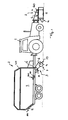
- a first attachment 2 in the form of a harvester attached which is designed according to an advantageous embodiment of the invention in the form of a loading wagon 20, and a second attachment 2 in the form of a front mower 60 grown.
- the in Fig. 1 Wagon 2 shown here comprises several working units 3, each comprising a rotatably mounted working body 4.
- a first working unit 3 in this case forms the pickup 17 comprising a spiked roller 9 for collecting crop from the ground.
- the spiked roller 9, which may be suspended in the illustrated embodiment, possibly also oscillating, is thereby rotationally driven to promote lying on the ground crop in a conveyor channel.
- Said spiked roller 9 may include a further development of the invention, a tubular work body 4, projecting from the circumference of spiky driver tines.
- Another working unit 3 is a conveyor comprising a conveyor rotor 10, which takes over the picked up by the pickup 17 crop and promotes the crop 11 of the loading wagon 20.
- the conveyor rotor 10 may include a further development of the invention, a tubular work body 4, protrude from the periphery rotor tines that promote the crop.
- a further working unit 3 of the loading wagon 20 is also a scraper floor 200, with which the crop material conveyed into the crop storage 11 can be distributed into said crop storage 11 and transported to a rear-side storage wall or a discharge output provided there.
- the said scraper floor 200 likewise comprises a rotationally drivable drive element 201, for example in the form of a pinion, with which an endlessly circulating drive element of the floor conveyor can be driven.
- Said drive element 201 can in this case for example sit on a shaft-shaped or tubular drive element which extends transversely across the floor.
- Another working unit 3 is a rear side arranged on the crop 11 storage metering device 300, which may for example comprise a plurality of metering rollers, by means of which the crop when unloading from the crop 11 can be accurately metered.
- Said metering rollers of the metering device 300 may also comprise a tubular working body 4, which may comprise entrainment members mounted on the outer circumference.
- an electric motor 6 which is advantageously completely received in the interior of the respective working body 4 and completely surrounded by the tubular or cylindrical work body 4 at least circumferentially ,
- the electric motor 6 can sit directly on the axis of the tubular working body 4, which also supports said working body 4 and rotatably supports.
- a conventional internal rotor motor can also be used as an alternative to such a tubular motor.
- the aforementioned tubular motor, which is housed inside the respective working body is preferred because it offers advantages in terms of space and protection for the engine.
- the electric motor 6 can also be installed without such a pipe jacket, in particular if the working unit to be driven does not comprise a tubular working body.
- the electric motor 6 may be connected to a gear not shown separately, for example in the form of a multi-stage planetary gear, which is advantageously also supported on the said axis and may also be included in the invention of the working body in development of the invention.
- the electric motor 6 of the respective drive is in this case controlled by a control device 30 in terms of speed and torque to adjust the working movement of the respective working unit to the operating conditions, in particular the size and density of a Erntegutschwads and the driving speed of the tractor.
- the control device 30 predetermines a setpoint speed or a setpoint torque for the respective electric motor 6.
- the rotational position and the rotational speed of the respective electric motor 6 is determined, by a determination device 31, in the illustrated embodiment according to Fig. 5 together with the inverter 40 is combined to form an electronic assembly, the input side receives the target speed and the target torque and, on the part of the inverter 40, the power supply, while the output side drives the electric motor 6, which is self-sensorless or encoderless.
- Said determination device 31 comprises determination means 32 for determining the spatial, magnetic conductance fluctuations, from which the rotational position of the electric motor 6 can be determined, wherein detection means are preferably provided for detecting a DC link current increase and / or an intermediate circuit voltage and / or a current switching state of the converter 40, From which the determining means 32 then the conductance fluctuation can be determined. For the determination of the rotor position and the speed can proceed, as in the Scriptures AT 502 615 B1 or the scripture AT 406 722 B explained in more detail.
- the specific rotational position and the specific speed are processed by the controller 22 and used to drive the inverter 40 to adjust the electric motor 6 to the desired target speed and / or the desired target torque.
- the controller 22 may vary the drive speed of the electric motors 6 of the power units to respond to or compensate for variations in the external load. If, for example, the crop swath to be picked up becomes larger, as a result of which the power consumption of the electric motor 6 of the spiked roller 9 and / or of the conveyor rotor 10 increases, the controller 22 can increase the speed of the electric motor 6 in order to cope with the increasing crop flow.
- the controller 22 may also provide an actuating signal for the traveling speed of the tractor to change the traveling speed of the tractor and to adapt to the varying Erntegutstrom.
- This control signal can be provided either in the form of a display, so that the driver implements the control signal.
- a semi-automatic or fully automatic implementation can be provided by a cruise control.
- the controller 22 can increase the driving speed to operate the loader wagon 2 with the fullest possible utilization of its performance.
- the reduction in the crop flow or swath is in this case determined by a drop in the power consumption of the electric motor 6 of the spiked roller 9 and / or the conveyor rotor 10.
- the other working units 3 of the loading wagon 20 and the working units 3 of other harvesting or tillage machines can be controlled by means of an electric motor 6 having drive 5 and a corresponding controller 22, as the other figures show.
- loading wagon 20 instead of the in Fig. 1 shown loading wagon 20 have a baler in a corresponding manner controlled electric motors, for example, to drive the spiked roller of the pickup of the press and / or to drive the Conveyor rotor, with which the crop is conveyed into the press chamber and / or to drive the working units of the press device itself.
- controlled electric motors for example, to drive the spiked roller of the pickup of the press and / or to drive the Conveyor rotor, with which the crop is conveyed into the press chamber and / or to drive the working units of the press device itself.
- This in Fig. 1 shown front mounted mower 60 may include in a conventional manner, a plurality of knife drums or knife rotors 13 which are driven to upright axes and have radially projecting or swinging knife to cut the standing crop.
- the aforementioned blade rotors 13 may have in a similar manner as the self-loading wagon 2 tubular Häkorpi 4, in the interior in the in Fig. 2 As shown, an electric motor 6 and a transmission can be arranged to drive the blade rotors 13.
- the mower 22 may also include a conditioning rotor downstream of the cutter rotors 13 conditioning the cut crop by mechanical processing, in particular kinks and / or breaks the surface to allow faster drying.
- Said conditioning roller advantageously also comprises a working body into which a drive comprising an electric motor and possibly a transmission is integrated.
- the mower 22 may be provided with a cross conveyor, for example in the form of a cross conveyor belt, which is downstream of said conditioning roller and promotes the cut and conditioned crop transversely to the direction of travel, for example, to spend it from the track of the tractor.
- Said cross conveyor can advantageously also comprise a working body, for example in the form of deflection rollers, around which the transverse conveyor belt revolves and which can be driven by a drive comprising an electric motor and optionally a transmission.
- the electric motors 6 of the blade rotors 13 and / or the conditioning roller and / or the cross conveyor can in the manner described above of a Controllers 22 are controlled to respond to or compensate for variations in the external load by the power consumption of the electric motor 6 is monitored and regulated accordingly. Varying external loads can be caused for example by a different density and / or high growth of the field to be mowed.
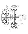
- the attachment 2 may also be designed as a haymaking machine in the form of a rake, which in the illustrated embodiment has four rotatably rotatable about a respective upright rotary rake 16.
- the aforementioned rotary gyros 16 of the haymaking machine 23 may in this case in each case comprise a working body 4 in which a drive 5 with an electric motor 6 and possibly a transmission are integrated.
- the electric motor 6 is controlled by means of the regulator 22 already explained.
- the attachment 2 may also be designed as a harrow, which in the illustrated embodiment has a transversely oriented to the direction of series of tine rotors 25, which are rotationally driven in each case about an upright axis.
- the said rotary rakes in each case comprise downward directed to the ground harrow tines and a working body 4, in which a drive 5 with an electric motor 6 and possibly a transmission are integrated.
- the harrow can have for each tine 25 separately an electric motor 6.
- one or more tine rotors 25 may be grouped together and driven by an electric motor in the working body of a tine rotator.
- the harrow tines 25 a roller 26, which may optionally be designed drivable by a roller drive.
- An electric motor of the roller drive may be arranged in said roller 26.
- the electric motors 6 are controlled in the manner mentioned by the controller 22.
- the attachment 2 may also be designed as a drill 70, which in the illustrated embodiment in the form of a Seeierikombination an upstream tillage group 80 and the discharge 90 for Spreading the grains of the seed includes.
- Said dispensing device 90 advantageously comprises metering wheels 100, which can each be driven by electric motors.
- a suitable controller 22 controls the rotational speed of the metering wheels 100 as a function of relevant operating parameters such as driving speed, target application density, which can vary from field section to field section, and, for example, seed.
- a tire packer unit of the seeder combination can also be driven by an electromotive tire packer drive.
- a suitable controller controls here the speed of the electric motor of the packer drive and thus the speed of the packer wheels, for example, depending on a target driving speed, which may vary depending on soil parameters orfilden seed.
Landscapes
- Life Sciences & Earth Sciences (AREA)
- Engineering & Computer Science (AREA)
- Power Engineering (AREA)
- Environmental Sciences (AREA)
- Zoology (AREA)
- Mechanical Engineering (AREA)
- Soil Sciences (AREA)
- Agricultural Machines (AREA)
- Soil Working Implements (AREA)
- Fertilizing (AREA)
Priority Applications (1)
| Application Number | Priority Date | Filing Date | Title |
|---|---|---|---|
| SI201131676T SI2448108T1 (sl) | 2010-10-19 | 2011-10-10 | Poljedelski delovni stroj |
Applications Claiming Priority (1)
| Application Number | Priority Date | Filing Date | Title |
|---|---|---|---|
| DE102010048876A DE102010048876A1 (de) | 2010-10-19 | 2010-10-19 | Landwirtschaftliche Arbeitsmaschine |
Publications (3)
| Publication Number | Publication Date |
|---|---|
| EP2448108A2 true EP2448108A2 (fr) | 2012-05-02 |
| EP2448108A3 EP2448108A3 (fr) | 2014-12-03 |
| EP2448108B1 EP2448108B1 (fr) | 2018-12-05 |
Family
ID=44799529
Family Applications (1)
| Application Number | Title | Priority Date | Filing Date |
|---|---|---|---|
| EP11008172.6A Not-in-force EP2448108B1 (fr) | 2010-10-19 | 2011-10-10 | Machine de travail agricole |
Country Status (5)
| Country | Link |
|---|---|
| EP (1) | EP2448108B1 (fr) |
| DE (1) | DE102010048876A1 (fr) |
| DK (1) | DK2448108T3 (fr) |
| ES (1) | ES2713474T3 (fr) |
| SI (1) | SI2448108T1 (fr) |
Cited By (1)
| Publication number | Priority date | Publication date | Assignee | Title |
|---|---|---|---|---|
| US11697348B2 (en) | 2020-06-23 | 2023-07-11 | Toyota Motor Engineering & Manufacturing North America, Inc. | Farm-based predictive efficient drive |
Families Citing this family (2)
| Publication number | Priority date | Publication date | Assignee | Title |
|---|---|---|---|---|
| DE102015221996A1 (de) | 2015-11-09 | 2017-05-11 | Zf Friedrichshafen Ag | Anbaugerät für eine landwirtschaftliche und/oder forstwirtschaftliche Arbeitsmaschine und Gespann |
| DE102016204090A1 (de) | 2016-03-11 | 2017-09-14 | Zf Friedrichshafen Ag | Anhängewagen für ein straßengebundenes Zugfahrzeug, Gespann sowie Verfahren zum Antreiben und Bremsen eines Anhängewagens |
Citations (7)
| Publication number | Priority date | Publication date | Assignee | Title |
|---|---|---|---|---|
| AT406722B (de) | 1998-01-30 | 2000-08-25 | Schroedl Manfred Dipl Ing Dr | Verfahren zur feldorientierten regelung einer mechanisch drehgeberlosen drehstrommaschine |
| DE10303050A1 (de) | 2003-01-24 | 2004-08-26 | Gkn Walterscheid Gmbh | Generatoreinheit für Traktoren und elektrisches Antriebssystem für Landmaschinen |
| DE102005019362A1 (de) | 2005-04-26 | 2006-11-02 | Deere & Company, Moline | Elektrische Schnittstellenvorrichtung zum Übertragen elektrischer Energie zwischen einem Fahrzeug und einem an das Fahrzeug ankoppelbaren Arbeitsgerät |
| AT502615B1 (de) | 2005-07-22 | 2008-05-15 | Schroedl Manfred Dipl Ing Dr | Verfahren zur direkten regelung der reaktanz einer drehstrommaschine |
| DE102007024645A1 (de) | 2007-05-24 | 2008-11-27 | Deere & Company, Moline | Vorrichtung zur elektrischen Versorgung eines landwirtschaftlichen Arbeitsfahrzeugs und/oder eines an das Arbeitsfahrzeug ankoppelbaren Anbaugeräts |
| DE102007024644A1 (de) | 2007-05-24 | 2008-11-27 | Deere & Company, Moline | Vorrichtung zum Übertragen elektrischer Energie von einem landwirtschaftlichen Arbeitsfahrzeug auf ein an das Arbeitsfahrzeug ankoppelbares Anbaugerät |
| DE102007038510A1 (de) | 2007-08-14 | 2009-02-19 | Rauch Landmaschinenfabrik Gmbh | Vorrichtung zum Dosieren und Verteilen von landwirtschaftlichen und kommunalen Schüttgütern |
Family Cites Families (4)
| Publication number | Priority date | Publication date | Assignee | Title |
|---|---|---|---|---|
| DE19710082A1 (de) * | 1997-03-12 | 1998-10-01 | Deere & Co | Antriebssystem für Nutzfahrzeuge |
| US20060059879A1 (en) * | 2004-09-20 | 2006-03-23 | Edmond Brian W | Multifunction electric tractor |
| DE102009009628B4 (de) * | 2009-02-19 | 2020-06-18 | Pöttinger Landtechnik Gmbh | Landwirtschaftliches Anbaugerät |
| EP2421354B1 (fr) * | 2009-04-22 | 2013-01-23 | Technische Universität Dresden | Machine de récolte avec un batteur cylindrique entraîné électriquement |
-
2010
- 2010-10-19 DE DE102010048876A patent/DE102010048876A1/de not_active Withdrawn
-
2011
- 2011-10-10 ES ES11008172T patent/ES2713474T3/es active Active
- 2011-10-10 EP EP11008172.6A patent/EP2448108B1/fr not_active Not-in-force
- 2011-10-10 SI SI201131676T patent/SI2448108T1/sl unknown
- 2011-10-10 DK DK11008172.6T patent/DK2448108T3/en active
Patent Citations (7)
| Publication number | Priority date | Publication date | Assignee | Title |
|---|---|---|---|---|
| AT406722B (de) | 1998-01-30 | 2000-08-25 | Schroedl Manfred Dipl Ing Dr | Verfahren zur feldorientierten regelung einer mechanisch drehgeberlosen drehstrommaschine |
| DE10303050A1 (de) | 2003-01-24 | 2004-08-26 | Gkn Walterscheid Gmbh | Generatoreinheit für Traktoren und elektrisches Antriebssystem für Landmaschinen |
| DE102005019362A1 (de) | 2005-04-26 | 2006-11-02 | Deere & Company, Moline | Elektrische Schnittstellenvorrichtung zum Übertragen elektrischer Energie zwischen einem Fahrzeug und einem an das Fahrzeug ankoppelbaren Arbeitsgerät |
| AT502615B1 (de) | 2005-07-22 | 2008-05-15 | Schroedl Manfred Dipl Ing Dr | Verfahren zur direkten regelung der reaktanz einer drehstrommaschine |
| DE102007024645A1 (de) | 2007-05-24 | 2008-11-27 | Deere & Company, Moline | Vorrichtung zur elektrischen Versorgung eines landwirtschaftlichen Arbeitsfahrzeugs und/oder eines an das Arbeitsfahrzeug ankoppelbaren Anbaugeräts |
| DE102007024644A1 (de) | 2007-05-24 | 2008-11-27 | Deere & Company, Moline | Vorrichtung zum Übertragen elektrischer Energie von einem landwirtschaftlichen Arbeitsfahrzeug auf ein an das Arbeitsfahrzeug ankoppelbares Anbaugerät |
| DE102007038510A1 (de) | 2007-08-14 | 2009-02-19 | Rauch Landmaschinenfabrik Gmbh | Vorrichtung zum Dosieren und Verteilen von landwirtschaftlichen und kommunalen Schüttgütern |
Cited By (1)
| Publication number | Priority date | Publication date | Assignee | Title |
|---|---|---|---|---|
| US11697348B2 (en) | 2020-06-23 | 2023-07-11 | Toyota Motor Engineering & Manufacturing North America, Inc. | Farm-based predictive efficient drive |
Also Published As
| Publication number | Publication date |
|---|---|
| EP2448108B1 (fr) | 2018-12-05 |
| SI2448108T1 (sl) | 2019-05-31 |
| EP2448108A3 (fr) | 2014-12-03 |
| DE102010048876A1 (de) | 2012-04-19 |
| DK2448108T3 (en) | 2019-02-18 |
| ES2713474T3 (es) | 2019-05-22 |
Similar Documents
| Publication | Publication Date | Title |
|---|---|---|
| EP2286657B1 (fr) | Machine agricole | |
| EP2936969B1 (fr) | Combinaison d'un véhicule de traction et d'une moissonneuse tirée par celui-ci | |
| EP1862057B1 (fr) | Attachement pour la récolte des plantes à tige | |
| EP2502477B1 (fr) | Elément auxiliaire agricole | |
| DE10134137B4 (de) | Selbstfahrende landwirtschaftliche Erntemaschine | |
| DE102010010862B4 (de) | Heuwerbungsmaschine | |
| DE102013100793A1 (de) | Kombination aus einem Zugfahrzeug und einer davon gezogenen landwirtschaftlichen Erntemaschine | |
| DE102004029953A1 (de) | Erntevorsatzantrieb | |
| EP3326446B1 (fr) | Dispositif de commande de vitesse d'une moissonneuse | |
| EP3607815B1 (fr) | Appareil de traitement agricole | |
| DE102007004576A1 (de) | Landwirtschaftliche Arbeitsmaschine | |
| BE1029376B1 (de) | Antriebsanordnung einer Konditioniereinrichtung eines Feldhäckslers mit einem elektrischen Antriebsstrang | |
| EP2281434A2 (fr) | Appareil doté d'un dispositif de transport transversal et d'une adaptation de couple | |
| EP3257353B1 (fr) | Machine agricole et procede de fonctionnement d'une machine agricole | |
| DE102007018321A1 (de) | Erntemaschine | |
| DE102010010861A1 (de) | Landmaschine | |
| EP2448108B1 (fr) | Machine de travail agricole | |
| DE102008014998A1 (de) | Antrieb der Ladevorrichtung einer Erntemaschine | |
| EP2168420B1 (fr) | Moissonneuse agricole | |
| DE102010010041B4 (de) | Landwirtschaftliches Anbaugerät | |
| EP4548741A1 (fr) | Procédé de traitement de champ | |
| BE1022788B1 (de) | Maschine zum mähen von stängelartigem erntegut mit sukzessive ansteigender querfördergeschwindigkeit | |
| EP2220928B1 (fr) | Machine agricole | |
| EP1576870A1 (fr) | Récolteuse | |
| DE102011083941A1 (de) | Rundballenpresse zur Erzeugung von Ballen aus Erntegutresten |
Legal Events
| Date | Code | Title | Description |
|---|---|---|---|
| PUAI | Public reference made under article 153(3) epc to a published international application that has entered the european phase |
Free format text: ORIGINAL CODE: 0009012 |
|
| AK | Designated contracting states |
Kind code of ref document: A2 Designated state(s): AL AT BE BG CH CY CZ DE DK EE ES FI FR GB GR HR HU IE IS IT LI LT LU LV MC MK MT NL NO PL PT RO RS SE SI SK SM TR |
|
| AX | Request for extension of the european patent |
Extension state: BA ME |
|
| RIN1 | Information on inventor provided before grant (corrected) |
Inventor name: BALDINGER, MARKUS, DIPL.-ING. Inventor name: BALDINGER, MARTIN, DR. Inventor name: HOFINGER, MARKUS |
|
| PUAL | Search report despatched |
Free format text: ORIGINAL CODE: 0009013 |
|
| AK | Designated contracting states |
Kind code of ref document: A3 Designated state(s): AL AT BE BG CH CY CZ DE DK EE ES FI FR GB GR HR HU IE IS IT LI LT LU LV MC MK MT NL NO PL PT RO RS SE SI SK SM TR |
|
| AX | Request for extension of the european patent |
Extension state: BA ME |
|
| RIC1 | Information provided on ipc code assigned before grant |
Ipc: H02P 21/00 20060101AFI20141028BHEP Ipc: H02P 21/14 20060101ALI20141028BHEP Ipc: H02P 6/18 20060101ALI20141028BHEP |
|
| 17P | Request for examination filed |
Effective date: 20150319 |
|
| RAP1 | Party data changed (applicant data changed or rights of an application transferred) |
Owner name: POETTINGER LANDTECHNIK GMBH |
|
| STAA | Information on the status of an ep patent application or granted ep patent |
Free format text: STATUS: EXAMINATION IS IN PROGRESS |
|
| 17Q | First examination report despatched |
Effective date: 20170425 |
|
| REG | Reference to a national code |
Ref country code: DE Ref legal event code: R079 Ref document number: 502011015105 Country of ref document: DE Free format text: PREVIOUS MAIN CLASS: H02P0021000000 Ipc: H02P0006180000 |
|
| GRAP | Despatch of communication of intention to grant a patent |
Free format text: ORIGINAL CODE: EPIDOSNIGR1 |
|
| STAA | Information on the status of an ep patent application or granted ep patent |
Free format text: STATUS: GRANT OF PATENT IS INTENDED |
|
| RIC1 | Information provided on ipc code assigned before grant |
Ipc: A01D 69/02 20060101ALI20180612BHEP Ipc: H02P 6/18 20060101AFI20180612BHEP Ipc: H02P 21/24 20160101ALI20180612BHEP Ipc: A01B 59/00 20060101ALI20180612BHEP |
|
| INTG | Intention to grant announced |
Effective date: 20180629 |
|
| GRAS | Grant fee paid |
Free format text: ORIGINAL CODE: EPIDOSNIGR3 |
|
| GRAA | (expected) grant |
Free format text: ORIGINAL CODE: 0009210 |
|
| GRAA | (expected) grant |
Free format text: ORIGINAL CODE: 0009210 |
|
| STAA | Information on the status of an ep patent application or granted ep patent |
Free format text: STATUS: THE PATENT HAS BEEN GRANTED |
|
| AK | Designated contracting states |
Kind code of ref document: B1 Designated state(s): AL AT BE BG CH CY CZ DE DK EE ES FI FR GB GR HR HU IE IS IT LI LT LU LV MC MK MT NL NO PL PT RO RS SE SI SK SM TR |
|
| REG | Reference to a national code |
Ref country code: GB Ref legal event code: FG4D Free format text: NOT ENGLISH |
|
| REG | Reference to a national code |
Ref country code: CH Ref legal event code: EP Ref country code: CH Ref legal event code: NV Representative=s name: KELLER AND PARTNER PATENTANWAELTE AG, CH |
|
| REG | Reference to a national code |
Ref country code: AT Ref legal event code: REF Ref document number: 1074316 Country of ref document: AT Kind code of ref document: T Effective date: 20181215 |
|
| REG | Reference to a national code |
Ref country code: IE Ref legal event code: FG4D Free format text: LANGUAGE OF EP DOCUMENT: GERMAN |
|
| REG | Reference to a national code |
Ref country code: DE Ref legal event code: R096 Ref document number: 502011015105 Country of ref document: DE |
|
| REG | Reference to a national code |
Ref country code: DK Ref legal event code: T3 Effective date: 20190212 |
|
| REG | Reference to a national code |
Ref country code: NL Ref legal event code: FP |
|
| REG | Reference to a national code |
Ref country code: LT Ref legal event code: MG4D |
|
| PG25 | Lapsed in a contracting state [announced via postgrant information from national office to epo] |
Ref country code: LV Free format text: LAPSE BECAUSE OF FAILURE TO SUBMIT A TRANSLATION OF THE DESCRIPTION OR TO PAY THE FEE WITHIN THE PRESCRIBED TIME-LIMIT Effective date: 20181205 Ref country code: LT Free format text: LAPSE BECAUSE OF FAILURE TO SUBMIT A TRANSLATION OF THE DESCRIPTION OR TO PAY THE FEE WITHIN THE PRESCRIBED TIME-LIMIT Effective date: 20181205 Ref country code: HR Free format text: LAPSE BECAUSE OF FAILURE TO SUBMIT A TRANSLATION OF THE DESCRIPTION OR TO PAY THE FEE WITHIN THE PRESCRIBED TIME-LIMIT Effective date: 20181205 Ref country code: BG Free format text: LAPSE BECAUSE OF FAILURE TO SUBMIT A TRANSLATION OF THE DESCRIPTION OR TO PAY THE FEE WITHIN THE PRESCRIBED TIME-LIMIT Effective date: 20190305 Ref country code: FI Free format text: LAPSE BECAUSE OF FAILURE TO SUBMIT A TRANSLATION OF THE DESCRIPTION OR TO PAY THE FEE WITHIN THE PRESCRIBED TIME-LIMIT Effective date: 20181205 Ref country code: NO Free format text: LAPSE BECAUSE OF FAILURE TO SUBMIT A TRANSLATION OF THE DESCRIPTION OR TO PAY THE FEE WITHIN THE PRESCRIBED TIME-LIMIT Effective date: 20190305 |
|
| REG | Reference to a national code |
Ref country code: ES Ref legal event code: FG2A Ref document number: 2713474 Country of ref document: ES Kind code of ref document: T3 Effective date: 20190522 |
|
| PG25 | Lapsed in a contracting state [announced via postgrant information from national office to epo] |
Ref country code: GR Free format text: LAPSE BECAUSE OF FAILURE TO SUBMIT A TRANSLATION OF THE DESCRIPTION OR TO PAY THE FEE WITHIN THE PRESCRIBED TIME-LIMIT Effective date: 20190306 Ref country code: SE Free format text: LAPSE BECAUSE OF FAILURE TO SUBMIT A TRANSLATION OF THE DESCRIPTION OR TO PAY THE FEE WITHIN THE PRESCRIBED TIME-LIMIT Effective date: 20181205 Ref country code: RS Free format text: LAPSE BECAUSE OF FAILURE TO SUBMIT A TRANSLATION OF THE DESCRIPTION OR TO PAY THE FEE WITHIN THE PRESCRIBED TIME-LIMIT Effective date: 20181205 Ref country code: AL Free format text: LAPSE BECAUSE OF FAILURE TO SUBMIT A TRANSLATION OF THE DESCRIPTION OR TO PAY THE FEE WITHIN THE PRESCRIBED TIME-LIMIT Effective date: 20181205 |
|
| PG25 | Lapsed in a contracting state [announced via postgrant information from national office to epo] |
Ref country code: CZ Free format text: LAPSE BECAUSE OF FAILURE TO SUBMIT A TRANSLATION OF THE DESCRIPTION OR TO PAY THE FEE WITHIN THE PRESCRIBED TIME-LIMIT Effective date: 20181205 Ref country code: PT Free format text: LAPSE BECAUSE OF FAILURE TO SUBMIT A TRANSLATION OF THE DESCRIPTION OR TO PAY THE FEE WITHIN THE PRESCRIBED TIME-LIMIT Effective date: 20190405 Ref country code: PL Free format text: LAPSE BECAUSE OF FAILURE TO SUBMIT A TRANSLATION OF THE DESCRIPTION OR TO PAY THE FEE WITHIN THE PRESCRIBED TIME-LIMIT Effective date: 20181205 |
|
| PG25 | Lapsed in a contracting state [announced via postgrant information from national office to epo] |
Ref country code: SK Free format text: LAPSE BECAUSE OF FAILURE TO SUBMIT A TRANSLATION OF THE DESCRIPTION OR TO PAY THE FEE WITHIN THE PRESCRIBED TIME-LIMIT Effective date: 20181205 Ref country code: RO Free format text: LAPSE BECAUSE OF FAILURE TO SUBMIT A TRANSLATION OF THE DESCRIPTION OR TO PAY THE FEE WITHIN THE PRESCRIBED TIME-LIMIT Effective date: 20181205 Ref country code: IS Free format text: LAPSE BECAUSE OF FAILURE TO SUBMIT A TRANSLATION OF THE DESCRIPTION OR TO PAY THE FEE WITHIN THE PRESCRIBED TIME-LIMIT Effective date: 20190405 Ref country code: EE Free format text: LAPSE BECAUSE OF FAILURE TO SUBMIT A TRANSLATION OF THE DESCRIPTION OR TO PAY THE FEE WITHIN THE PRESCRIBED TIME-LIMIT Effective date: 20181205 Ref country code: SM Free format text: LAPSE BECAUSE OF FAILURE TO SUBMIT A TRANSLATION OF THE DESCRIPTION OR TO PAY THE FEE WITHIN THE PRESCRIBED TIME-LIMIT Effective date: 20181205 |
|
| REG | Reference to a national code |
Ref country code: DE Ref legal event code: R097 Ref document number: 502011015105 Country of ref document: DE |
|
| PLBE | No opposition filed within time limit |
Free format text: ORIGINAL CODE: 0009261 |
|
| STAA | Information on the status of an ep patent application or granted ep patent |
Free format text: STATUS: NO OPPOSITION FILED WITHIN TIME LIMIT |
|
| 26N | No opposition filed |
Effective date: 20190906 |
|
| PG25 | Lapsed in a contracting state [announced via postgrant information from national office to epo] |
Ref country code: TR Free format text: LAPSE BECAUSE OF FAILURE TO SUBMIT A TRANSLATION OF THE DESCRIPTION OR TO PAY THE FEE WITHIN THE PRESCRIBED TIME-LIMIT Effective date: 20181205 |
|
| PG25 | Lapsed in a contracting state [announced via postgrant information from national office to epo] |
Ref country code: MC Free format text: LAPSE BECAUSE OF FAILURE TO SUBMIT A TRANSLATION OF THE DESCRIPTION OR TO PAY THE FEE WITHIN THE PRESCRIBED TIME-LIMIT Effective date: 20181205 |
|
| REG | Reference to a national code |
Ref country code: CH Ref legal event code: PL |
|
| PG25 | Lapsed in a contracting state [announced via postgrant information from national office to epo] |
Ref country code: LI Free format text: LAPSE BECAUSE OF NON-PAYMENT OF DUE FEES Effective date: 20191031 Ref country code: CH Free format text: LAPSE BECAUSE OF NON-PAYMENT OF DUE FEES Effective date: 20191031 Ref country code: LU Free format text: LAPSE BECAUSE OF NON-PAYMENT OF DUE FEES Effective date: 20191010 |
|
| REG | Reference to a national code |
Ref country code: BE Ref legal event code: MM Effective date: 20191031 |
|
| PG25 | Lapsed in a contracting state [announced via postgrant information from national office to epo] |
Ref country code: BE Free format text: LAPSE BECAUSE OF NON-PAYMENT OF DUE FEES Effective date: 20191031 |
|
| GBPC | Gb: european patent ceased through non-payment of renewal fee |
Effective date: 20191010 |
|
| PG25 | Lapsed in a contracting state [announced via postgrant information from national office to epo] |
Ref country code: IT Free format text: LAPSE BECAUSE OF NON-PAYMENT OF DUE FEES Effective date: 20191010 Ref country code: IE Free format text: LAPSE BECAUSE OF NON-PAYMENT OF DUE FEES Effective date: 20191010 Ref country code: GB Free format text: LAPSE BECAUSE OF NON-PAYMENT OF DUE FEES Effective date: 20191010 |
|
| PGFP | Annual fee paid to national office [announced via postgrant information from national office to epo] |
Ref country code: DK Payment date: 20200904 Year of fee payment: 10 Ref country code: NL Payment date: 20200903 Year of fee payment: 10 |
|
| PG25 | Lapsed in a contracting state [announced via postgrant information from national office to epo] |
Ref country code: SI Free format text: LAPSE BECAUSE OF NON-PAYMENT OF DUE FEES Effective date: 20191011 |
|
| REG | Reference to a national code |
Ref country code: AT Ref legal event code: MM01 Ref document number: 1074316 Country of ref document: AT Kind code of ref document: T Effective date: 20191010 |
|
| PG25 | Lapsed in a contracting state [announced via postgrant information from national office to epo] |
Ref country code: AT Free format text: LAPSE BECAUSE OF NON-PAYMENT OF DUE FEES Effective date: 20191010 |
|
| REG | Reference to a national code |
Ref country code: ES Ref legal event code: FD2A Effective date: 20210301 |
|
| PG25 | Lapsed in a contracting state [announced via postgrant information from national office to epo] |
Ref country code: CY Free format text: LAPSE BECAUSE OF FAILURE TO SUBMIT A TRANSLATION OF THE DESCRIPTION OR TO PAY THE FEE WITHIN THE PRESCRIBED TIME-LIMIT Effective date: 20181205 Ref country code: ES Free format text: LAPSE BECAUSE OF NON-PAYMENT OF DUE FEES Effective date: 20191011 |
|
| PG25 | Lapsed in a contracting state [announced via postgrant information from national office to epo] |
Ref country code: HU Free format text: LAPSE BECAUSE OF FAILURE TO SUBMIT A TRANSLATION OF THE DESCRIPTION OR TO PAY THE FEE WITHIN THE PRESCRIBED TIME-LIMIT; INVALID AB INITIO Effective date: 20111010 Ref country code: MT Free format text: LAPSE BECAUSE OF FAILURE TO SUBMIT A TRANSLATION OF THE DESCRIPTION OR TO PAY THE FEE WITHIN THE PRESCRIBED TIME-LIMIT Effective date: 20181205 |
|
| REG | Reference to a national code |
Ref country code: DK Ref legal event code: EBP Effective date: 20211031 |
|
| REG | Reference to a national code |
Ref country code: NL Ref legal event code: MM Effective date: 20211101 |
|
| PG25 | Lapsed in a contracting state [announced via postgrant information from national office to epo] |
Ref country code: MK Free format text: LAPSE BECAUSE OF FAILURE TO SUBMIT A TRANSLATION OF THE DESCRIPTION OR TO PAY THE FEE WITHIN THE PRESCRIBED TIME-LIMIT Effective date: 20181205 |
|
| PG25 | Lapsed in a contracting state [announced via postgrant information from national office to epo] |
Ref country code: NL Free format text: LAPSE BECAUSE OF NON-PAYMENT OF DUE FEES Effective date: 20211101 |
|
| PG25 | Lapsed in a contracting state [announced via postgrant information from national office to epo] |
Ref country code: DK Free format text: LAPSE BECAUSE OF NON-PAYMENT OF DUE FEES Effective date: 20211031 |
|
| PGFP | Annual fee paid to national office [announced via postgrant information from national office to epo] |
Ref country code: FR Payment date: 20221004 Year of fee payment: 12 |
|
| PGFP | Annual fee paid to national office [announced via postgrant information from national office to epo] |
Ref country code: DE Payment date: 20220921 Year of fee payment: 12 |
|
| P01 | Opt-out of the competence of the unified patent court (upc) registered |
Effective date: 20230613 |
|
| REG | Reference to a national code |
Ref country code: DE Ref legal event code: R119 Ref document number: 502011015105 Country of ref document: DE |
|
| PG25 | Lapsed in a contracting state [announced via postgrant information from national office to epo] |
Ref country code: FR Free format text: LAPSE BECAUSE OF NON-PAYMENT OF DUE FEES Effective date: 20231031 Ref country code: DE Free format text: LAPSE BECAUSE OF NON-PAYMENT OF DUE FEES Effective date: 20240501 |