EP2448375A2 - Agencement de circuit de démarrage destiné à l'allumage d'une lampe à décharge et d'une lampe haute pression - Google Patents
Agencement de circuit de démarrage destiné à l'allumage d'une lampe à décharge et d'une lampe haute pression Download PDFInfo
- Publication number
- EP2448375A2 EP2448375A2 EP11186309A EP11186309A EP2448375A2 EP 2448375 A2 EP2448375 A2 EP 2448375A2 EP 11186309 A EP11186309 A EP 11186309A EP 11186309 A EP11186309 A EP 11186309A EP 2448375 A2 EP2448375 A2 EP 2448375A2
- Authority
- EP
- European Patent Office
- Prior art keywords
- ignition
- temperature
- lamp
- transformer
- determined
- Prior art date
- Legal status (The legal status is an assumption and is not a legal conclusion. Google has not performed a legal analysis and makes no representation as to the accuracy of the status listed.)
- Withdrawn
Links
- 238000000034 method Methods 0.000 claims abstract description 18
- 239000003990 capacitor Substances 0.000 claims description 22
- 230000006870 function Effects 0.000 claims description 11
- 230000001105 regulatory effect Effects 0.000 claims description 5
- 238000009529 body temperature measurement Methods 0.000 claims description 4
- 230000005415 magnetization Effects 0.000 claims description 3
- 230000035699 permeability Effects 0.000 claims description 2
- 230000008569 process Effects 0.000 claims description 2
- 230000006399 behavior Effects 0.000 description 4
- 230000005540 biological transmission Effects 0.000 description 4
- 230000001419 dependent effect Effects 0.000 description 3
- 239000000463 material Substances 0.000 description 3
- 230000002093 peripheral effect Effects 0.000 description 3
- 229910000859 α-Fe Inorganic materials 0.000 description 3
- XEEYBQQBJWHFJM-UHFFFAOYSA-N Iron Chemical compound [Fe] XEEYBQQBJWHFJM-UHFFFAOYSA-N 0.000 description 2
- 230000001276 controlling effect Effects 0.000 description 2
- 239000000853 adhesive Substances 0.000 description 1
- 230000001070 adhesive effect Effects 0.000 description 1
- XAGFODPZIPBFFR-UHFFFAOYSA-N aluminium Chemical compound [Al] XAGFODPZIPBFFR-UHFFFAOYSA-N 0.000 description 1
- 229910052782 aluminium Inorganic materials 0.000 description 1
- 230000008901 benefit Effects 0.000 description 1
- 230000008859 change Effects 0.000 description 1
- 229910052742 iron Inorganic materials 0.000 description 1
- 238000005259 measurement Methods 0.000 description 1
- 238000011017 operating method Methods 0.000 description 1
- 230000002035 prolonged effect Effects 0.000 description 1
Images

Classifications
-
- H—ELECTRICITY
- H05—ELECTRIC TECHNIQUES NOT OTHERWISE PROVIDED FOR
- H05B—ELECTRIC HEATING; ELECTRIC LIGHT SOURCES NOT OTHERWISE PROVIDED FOR; CIRCUIT ARRANGEMENTS FOR ELECTRIC LIGHT SOURCES, IN GENERAL
- H05B41/00—Circuit arrangements or apparatus for igniting or operating discharge lamps
- H05B41/14—Circuit arrangements
- H05B41/26—Circuit arrangements in which the lamp is fed by power derived from DC by means of a converter, e.g. by high-voltage DC
- H05B41/28—Circuit arrangements in which the lamp is fed by power derived from DC by means of a converter, e.g. by high-voltage DC using static converters
- H05B41/288—Circuit arrangements in which the lamp is fed by power derived from DC by means of a converter, e.g. by high-voltage DC using static converters with semiconductor devices and specially adapted for lamps without preheating electrodes, e.g. for high-intensity discharge lamps, high-pressure mercury or sodium lamps or low-pressure sodium lamps
- H05B41/2881—Load circuits; Control thereof
- H05B41/2882—Load circuits; Control thereof the control resulting from an action on the static converter
- H05B41/2883—Load circuits; Control thereof the control resulting from an action on the static converter the controlled element being a DC/AC converter in the final stage, e.g. by harmonic mode starting
-
- H—ELECTRICITY
- H05—ELECTRIC TECHNIQUES NOT OTHERWISE PROVIDED FOR
- H05B—ELECTRIC HEATING; ELECTRIC LIGHT SOURCES NOT OTHERWISE PROVIDED FOR; CIRCUIT ARRANGEMENTS FOR ELECTRIC LIGHT SOURCES, IN GENERAL
- H05B41/00—Circuit arrangements or apparatus for igniting or operating discharge lamps
- H05B41/14—Circuit arrangements
- H05B41/36—Controlling
- H05B41/38—Controlling the intensity of light
- H05B41/382—Controlling the intensity of light during the transitional start-up phase
-
- Y—GENERAL TAGGING OF NEW TECHNOLOGICAL DEVELOPMENTS; GENERAL TAGGING OF CROSS-SECTIONAL TECHNOLOGIES SPANNING OVER SEVERAL SECTIONS OF THE IPC; TECHNICAL SUBJECTS COVERED BY FORMER USPC CROSS-REFERENCE ART COLLECTIONS [XRACs] AND DIGESTS
- Y02—TECHNOLOGIES OR APPLICATIONS FOR MITIGATION OR ADAPTATION AGAINST CLIMATE CHANGE
- Y02B—CLIMATE CHANGE MITIGATION TECHNOLOGIES RELATED TO BUILDINGS, e.g. HOUSING, HOUSE APPLIANCES OR RELATED END-USER APPLICATIONS
- Y02B20/00—Energy efficient lighting technologies, e.g. halogen lamps or gas discharge lamps
Definitions
- the invention relates to an ignition circuit for igniting a discharge lamp such as a high-pressure lamp with a control device for igniting the lamp, wherein a temperature sensor means is provided for detecting a temperature and a memory means for storing information relating to at least one operating parameter of the ignition circuit to be set in dependence on the detected temperature.
- the invention further relates to a method for operating such a Zündscensan extract.
- a generic ignition circuit is, for example, from EP 1 871 147 B1 known.
- the known electronic ballast for the lamp comprises an AC voltage generator which provides an AC voltage with different frequencies for igniting and operating the discharge lamp, wherein a control unit generates the control signals for the AC voltage generator, with which the frequency of the AC voltage for the lamp is set.
- a temperature sensor detects the ambient temperature, with the ignition frequency and thus the ignition voltage depending on the ambient temperature depending set or changed.
- the load circuit of the inverter is based on a series circuit of a choke and a capacitor, to which the lamp is connected in parallel.
- the frequency of the inverter is lowered to ignite the lamp in the direction of the resonant frequency, which is determined essentially by the choke and the capacitor.
- the resonant voltage increase on the capacitor ultimately leads to the ignition of the tube.
- This document also teaches to set the frequency of the inverter and thus the ignition voltage as a function of the ambient temperature of the lamp.
- the described embodiments of the generic arrangements are due to the knowledge that the respectively required ignition voltage of the lamps is temperature-dependent.
- ignition circuit arrangements with an ignition transformer are also known, which is connected on the primary side with a Zündimpulsausletesciens and secondary side with the lamp.
- the operating parameters of the ignition circuit are set so that in any given case, the ignition of the lamp takes place in a predetermined temperature interval.
- the invention has the object, a genus-forming Zündscensan extract educate so that even in the presence of a Zündübertragers the gentlest possible treatment of the lamp and the peripheral components is guaranteed.
- the ignition circuit arrangement according to the invention is characterized in that an ignition pulse triggering circuit and an ignition transformer is provided, which is connected on the primary side with the Zündimpulsausletesciens and secondary side with the lamp, wherein the ignition pulse triggering circuit having an input power source and a switch means, and wherein the temperature sensor means for determining the temperature is formed on the ignition transformer and that the control device is designed to set the at least one operating parameter as a function of the determined temperature at the ignition transformer and the stored information.
- the influence of the temperature on the transmission behavior, in particular the voltage level of the generated ignition pulse can be considered in the generation of the respective ignition pulse, so ultimately the generation can be avoided by unnecessarily high ignition pulses.
- a core of the ignition transformer may comprise, for example, a ferrite material, an aluminum material or an iron material.
- the setting of the at least one operating parameter may include, in particular, controlling or regulating this operating parameter.
- the indication "determination of the temperature at the ignition transformer" includes both the explicit measurement of the temperature at the location of the Zündübertragers and a calculation or estimation of the temperature at the Zündübertrager based on a temperature measurement at another location of the Zündscensan emblem or on or in the housing of the said ignition circuit. In any case, a certain temperature value is determined or detected at the ignition transformer, which then of the control device for setting the least one Operating parameters of the ignition circuit can be used.
- the ignition pulse triggering circuit comprises a controllable voltage regulator, which in particular feeds a surge capacitor of the ignition pulse triggering circuit, so that the generation of the ignition pulse and in particular the height of the ignition pulse can be set via the controllable voltage regulator.
- the operating parameter given above can be, for example, the output voltage of the controllable voltage regulator and / or the charging time within which the surge capacitor is fed by the voltage regulator.
- the ignition transformer can be arranged in a housing, wherein at least one sensor of the temperature sensor device is arranged on or in the housing.
- the sensor may preferably be attached to the ignition transformer with good thermal contact, in particular at the core of the ignition transformer.
- a thermal paste or a thermal adhesive are suitable.
- the storage of the information relating to the dependence of the at least one operating parameter to be set on the temperature can be carried out, for example, in the form of a characteristic curve, a plurality of value pairs or in the form of a lookup table in an associated memory means be.
- the control device can be set up to perform an interpolation from the stored data at detected intermediate values such as intermediate temperature values.
- the temperature sensor device can also be designed to detect the lamp temperature, for example by means of a sensor attached directly to the lamp.
- the invention achieves the above object with a method for operating an ignition circuit for igniting a discharge lamp, in particular a high-pressure lamp, wherein predetermined information regarding at least one operating parameter of the ignition circuit to be set as a function of a temperature is stored.
- the inventive method is characterized in that by means of a Zündimpulsauslöseschari a primary-side pulse is generated, which is transformed by means of a Zündübertragers and transmitted to the lamp, wherein a switch of the Zündimpulsauslösescaria for generating the primary-side ignition pulse is driven, and wherein the temperature determined at the ignition transformer is and sets a control device depending on the determined temperature at the ignition transformer and the stored information the at least one operating parameter, ie controls or regulates.
- the invention it is possible, for example when operating a given lamp to reduce the tolerance of the ignition voltage of about 15 kV to about 4 kV, which entails a considerable simplification of the necessary circuitry.
- a surge capacitor is charged in the Zündauslösescaria before the generation of the primary-side ignition pulse, wherein the charge is carried out as a function of the determined temperature at the ignition transformer.
- the charging voltage and / or the charging time can be set as a function of the temperature at the ignition transformer.
- the temperature can be measured adjacent to or on or in the ignition transformer.
- a temperature measurement is measured adjacent to or at the lamp and is closed by means of a predetermined heat transport model to the temperature at the ignition transformer.
- the at least one operating parameter is expediently set in such a way that the influence of the determined temperature or temperatures on the ignition process is substantially compensated.
- the influence of the Zündübertragers on the generation of the ignition pulse but also the influence of other components in setting the at least an operating parameters are taken into account.
- the operating parameter of the ignition circuit to be set for example, the output voltage of a voltage regulator for charging a surge capacitor, the capacity of the surge capacitor, the number of successive ignition pulses and / or the waiting time between two ignition attempts depending on the detected temperature at the ignition transformer or the charging time for charging of the surge capacitor can be adjusted.
- both the temperature at the ignition transformer and the temperature of the lamp are determined by different means and set the at least one operating parameter as a function of the two determined temperatures, i. be controlled or regulated.
- the term "different means" means that the two temperatures are independent, e.g. can be detected with different sensors.
- Such a method has the great advantage that, on the one hand, the dependence of the ignition voltage for safely igniting the lamp on the temperature of the lamp and on the other hand, the temperature-dependent transmission behavior of the Zündübertragers can be taken into account when setting the Zündscensan extract to their operation, so that ultimately ensures that the necessary level of the ignition pulse is set in each operating situation, without the components such as the lamp or the peripheral electronic components are unnecessarily burdened by excessive voltage pulses.
- the capacity of the lamp is also determined and taken into account in the definition of the at least one operating parameter.
- the capacity of the lamp can be determined conventionally. It changes due to use, and can affect have the necessary amount of ignition voltage.
- the at least one operating parameter of the ignition arrangement can in this case also be set, in particular controlled or regulated, as a function of the ascertained capacitance of the lamp.
- information can be stored in the form of a four-dimensional data field with which the three given values are temperature at the ignition transformer, the temperature of the lamp and the capacity of the lamp is assigned a value for the at least one operating parameter.
- Intermediate values can be determined in this embodiment, for example by interpolation.
- FIG 1 An ignition circuit ZA according to the invention is shown in FIG 1 shown.
- the ignition circuit ZA and the discharge lamp 1 are fed via the AC terminals B1, B2.
- This supply can be done, for example, directly via a supply network or via a controlled inverter.
- a choke coil 2 is provided in series with the lamp.
- a parallel to the lamp 1 arranged capacitor 3 feeds via the rectifier 4, a voltage regulator 5, which generates from the pulsating DC voltage a DC voltage with a constant output voltage for feeding the output side connected Zündimpulsauslösesconic.
- the ignition pulse triggering circuit comprises, as essential components, a surge capacitor 8 which can be charged by means of a controllable DC-DC converter 7 and which can be discharged via the primary coils 9a of an ignition transformer by closing a switch 10.
- a primary-side pulse generated in this way is transmitted to the secondary coil 9b via the coil core 9c, which in the described embodiment comprises a ferrite core, and thus superimposed on the supply of the lamp 1 as an ignition pulse.
- the ignition circuit described is controlled by a microcontroller 6, which controls the switch 10 to open and close via the control line S1. Furthermore, the microcontroller 6 is connected to the controllable voltage regulator 7 via the control line S2 for setting the output voltage of the regulator. As shown in the drawing, the microcontroller is also powered by the first voltage regulator 5.
- the microcontroller uses sensor information supplied to it by the temperature sensor device 12 or by the capacitance measuring device 13 via the digital lines M1, M2.
- the temperature sensor device 12 is for detecting the actual temperature of the Zündübertragerkerns 9c and for detecting the actual temperature of the lamp 1 is formed.
- appropriate temperature sensors are mounted on Zündübertragerkern or on the lamp. Their respective sensor signal is received by the device 12 and processed to determine the respective temperature.
- the temperature sensors may be designed, for example, as NTC, as PTC or as PT100. In principle, all temperature sensors can be used which provide the necessary accuracy in the temperature determination.
- the device 13 is designed to detect the actual capacity of the lamp 1.
- the lamp may be to ignite after a long break in operation, but it may also be the case that after a prolonged operation of the lamp off and shortly after the lamp is to be operated again.
- the ignition circuit or the associated operating method is designed to ignite both cold and hot lamps safely without electronic components of the device or the lamp being loaded by unnecessarily high ignition voltages.
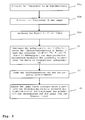
- the microcontroller After the microcontroller receives the command to ignite the lamp, this queries the temperature sensor device 12, the temperature TZ on the ignition transformer 9 and the temperature TL on the lamp 1 from. In the same way, the microcontroller 6 at the capacitance measuring device 13 queries the capacity of the lamp 1. After the acquisition of the requested actual values, these are transmitted to the microcontroller via the data lines M1, M2, see steps S1a, S1b, S1c in FIG FIG. 2 ,
- these values are polled at regular intervals so that they already exist when an ignition command occurs.
- information relating to the dependence of the charging parameters of the surge capacitor on the specified actual values TZ, TL and CL is stored in the microcontroller 6 so that one or more assigned, predetermined charging parameters are determined by the microcontroller for each determined value triple can, with which then the subsequent ignition can be performed.
- this information can be stored in the microcontroller in the form of a four-dimensional data field with which the three predetermined measured variables temperature at the ignition transformer, temperature of the lamp and lamp capacity a value for at least one operating parameter of the ignition circuit, such as the output voltage of the controller 6 to provide the charging voltage of the surge capacitor is assigned, see step S2 in the flowchart according to FIG. 2 , Intermediate values can be determined, for example, by interpolation.
- the at least one operating parameter of the ignition circuit arrangement, in the embodiment described, the at least one charging parameter for the surge capacitor can be determined by means of a polynomial stored in the control device.
- the information about the temperature and the capacity of the lamp are used to determine the ignition voltage necessary for these operating conditions.
- the information about the temperature at the ignition transformer is used to operate the Zündauslösescanno so that an ignition pulse of the desired height is generated at the lamp 1.
- step S4 the ignition of the lamp according to step S4 can take place.
- other operating parameters of the ignition circuit can be set depending on the determined actual values, for example the capacity of the surge capacitor, the number of successive ignition pulses and / or the waiting time between two ignition attempts or a combination of some or all operating parameters ignition circuit.
Landscapes
- Engineering & Computer Science (AREA)
- Power Engineering (AREA)
- Circuit Arrangements For Discharge Lamps (AREA)
Applications Claiming Priority (1)
| Application Number | Priority Date | Filing Date | Title |
|---|---|---|---|
| DE102010043081A DE102010043081A1 (de) | 2010-10-28 | 2010-10-28 | Zündschaltungsanordnung zum Zünden einer Entladungslampe wie einer Hochdrucklampe |
Publications (1)
| Publication Number | Publication Date |
|---|---|
| EP2448375A2 true EP2448375A2 (fr) | 2012-05-02 |
Family
ID=45023578
Family Applications (1)
| Application Number | Title | Priority Date | Filing Date |
|---|---|---|---|
| EP11186309A Withdrawn EP2448375A2 (fr) | 2010-10-28 | 2011-10-24 | Agencement de circuit de démarrage destiné à l'allumage d'une lampe à décharge et d'une lampe haute pression |
Country Status (2)
| Country | Link |
|---|---|
| EP (1) | EP2448375A2 (fr) |
| DE (1) | DE102010043081A1 (fr) |
Cited By (1)
| Publication number | Priority date | Publication date | Assignee | Title |
|---|---|---|---|---|
| WO2015015442A1 (fr) * | 2013-08-01 | 2015-02-05 | Greentek Green Solutions (2009) Ltd. | Commande d'allumage pour une lampe à décharge haute intensité à tube céramique céramique |
Citations (2)
| Publication number | Priority date | Publication date | Assignee | Title |
|---|---|---|---|---|
| DE3910900A1 (de) | 1989-04-04 | 1990-10-11 | Zumtobel Ag | Vorschaltgeraet fuer eine entladungslampe |
| EP1871147B1 (fr) | 2006-06-21 | 2009-09-02 | Osram Gesellschaft mit beschränkter Haftung | Procedé et ballast d'allumage de lampes à décharge |
Family Cites Families (7)
| Publication number | Priority date | Publication date | Assignee | Title |
|---|---|---|---|---|
| ZA862614B (en) * | 1986-04-08 | 1986-12-30 | David John Cockram | Controller for gas discharge lamps |
| US5319285A (en) * | 1992-07-23 | 1994-06-07 | Gte Products Corporation | Starting circuit for a high intensity discharge lamp |
| JP3606909B2 (ja) * | 1994-07-12 | 2005-01-05 | 三菱電機株式会社 | 交流放電灯点灯装置 |
| US6326733B1 (en) * | 2001-02-01 | 2001-12-04 | Starter Systems, Inc. | Electronic circuit to initiate and sustain current conduction in gaseous discharge lamps and method |
| JP2005142130A (ja) * | 2003-11-10 | 2005-06-02 | Matsushita Electric Works Ltd | 高圧放電灯点灯装置及び照明器具 |
| DE102004045834A1 (de) * | 2004-09-22 | 2006-03-23 | Bag Electronics Gmbh | Zündgerät |
| DE102006016827A1 (de) * | 2006-04-07 | 2007-10-11 | Bag Electronics Gmbh | Schaltungsanordnung für Hochdruck-Gasentladungslampen |
-
2010
- 2010-10-28 DE DE102010043081A patent/DE102010043081A1/de not_active Withdrawn
-
2011
- 2011-10-24 EP EP11186309A patent/EP2448375A2/fr not_active Withdrawn
Patent Citations (2)
| Publication number | Priority date | Publication date | Assignee | Title |
|---|---|---|---|---|
| DE3910900A1 (de) | 1989-04-04 | 1990-10-11 | Zumtobel Ag | Vorschaltgeraet fuer eine entladungslampe |
| EP1871147B1 (fr) | 2006-06-21 | 2009-09-02 | Osram Gesellschaft mit beschränkter Haftung | Procedé et ballast d'allumage de lampes à décharge |
Cited By (2)
| Publication number | Priority date | Publication date | Assignee | Title |
|---|---|---|---|---|
| WO2015015442A1 (fr) * | 2013-08-01 | 2015-02-05 | Greentek Green Solutions (2009) Ltd. | Commande d'allumage pour une lampe à décharge haute intensité à tube céramique céramique |
| US9474139B2 (en) | 2013-08-01 | 2016-10-18 | Greentek Green Solutions (2009) Ltd. | Control of ignition for a ceramic high intensity discharge lamp |
Also Published As
| Publication number | Publication date |
|---|---|
| DE102010043081A1 (de) | 2012-05-03 |
Similar Documents
| Publication | Publication Date | Title |
|---|---|---|
| DE102012007477B4 (de) | Verfahren zum Betreiben eines LLC-Resonanzwandlers für ein Leuchtmittel, Wandler und LED-Konverter | |
| EP0929911B1 (fr) | Procede et dispositif pour charger et decharger un element piezoelectrique | |
| DE3715162C2 (fr) | ||
| DE112010001214B4 (de) | Integrierte Schaltung eines Schaltnetzteil-(SMPS)-Reglers zum Bestimmen vonBetriebseigenschaften aus Informationen über Filterbauelemente | |
| DE68924874T2 (de) | Signalerzeugende Schaltung zur Ballaststeuerung von Entladungslampen. | |
| DE102015206264B4 (de) | Erfassen einer offenen Verbindung einer Hilfswicklung bei einer Schaltmodus-Energieversorgung | |
| DE102014219968A1 (de) | Verfahren zur Fremdobjekterkennung für eine Induktionsladevorrichtung und Induktionsladevorrichtung | |
| EP2216124A1 (fr) | Procédé destiné au réglage d'un poste de soudage à l'arc et poste de soudage à l'arc destiné à l'exécution du procédé | |
| EP1149455B1 (fr) | Procede et dispositif pour charger des accumulateurs | |
| DE102015214925A1 (de) | Verfahren zum Betrieb einer Magnetresonanzeinrichtung und Magnetresonanzeinrichtung | |
| EP1337133A2 (fr) | Circuit pour alimenter une lampe à décharge à fréquence variable pendant l' amorçage | |
| DE102008027029A1 (de) | Lampentyperkennung durch Leistungsfaktorkorrekturschaltung | |
| DE102014114768A1 (de) | Verfahren zum Laden einer Batterie eines Fahrzeugs | |
| EP2992736B1 (fr) | Procédé pour faire fonctionner un convertisseur led | |
| WO2007025976A1 (fr) | Ballast pour une lampe a decharge a prechauffage adaptatif | |
| EP2448375A2 (fr) | Agencement de circuit de démarrage destiné à l'allumage d'une lampe à décharge et d'une lampe haute pression | |
| EP2326147A2 (fr) | Appareil de commande de fonctionnement d'un moyen d'éclairage | |
| EP1424881B1 (fr) | Dispositif et méthode pour commander une lampe fluorescente | |
| DE102009019625A1 (de) | Verfahren zum Ermitteln eines Typs einer Gasentladungslampe und elektronisches Vorschaltgerät zum Betreiben von mindestens zwei unterschiedlichen Typen von Gasentladungslampen | |
| DE102008062949A1 (de) | Verfahren zur adaptiven Regelung eines Induktionserwärmungs- oder Plasmaprozesses | |
| DE102016206108B4 (de) | Verfahren zum Betreiben einer Hochstrom-Last in einem Bordnetz | |
| DE102014222116A1 (de) | Heizung für eine als Windschutz- oder Heckscheibe oder Spiegel ausgebildete und in oder an einem Fahrzeug anbringbare Komponente und Verfahren zum Beheizen einer solchen Komponente | |
| EP2796012B1 (fr) | Procédé, appareillage d'alimentation et système d'éclairage, avec détection d'effet de redressement de lampes | |
| DE102010063933A1 (de) | Betriebsgerät und Verfahren zum Betrieb von Gasentladungslampen | |
| EP2474206B1 (fr) | Correction de cosinus (phi) dans des ballasts à régulation du courant ou de la puissance pour des lampes |
Legal Events
| Date | Code | Title | Description |
|---|---|---|---|
| PUAI | Public reference made under article 153(3) epc to a published international application that has entered the european phase |
Free format text: ORIGINAL CODE: 0009012 |
|
| AK | Designated contracting states |
Kind code of ref document: A2 Designated state(s): AL AT BE BG CH CY CZ DE DK EE ES FI FR GB GR HR HU IE IS IT LI LT LU LV MC MK MT NL NO PL PT RO RS SE SI SK SM TR |
|
| AX | Request for extension of the european patent |
Extension state: BA ME |
|
| RAP1 | Party data changed (applicant data changed or rights of an application transferred) |
Owner name: BAG ENGINEERING GMBH |
|
| STAA | Information on the status of an ep patent application or granted ep patent |
Free format text: STATUS: THE APPLICATION IS DEEMED TO BE WITHDRAWN |
|
| 18D | Application deemed to be withdrawn |
Effective date: 20150501 |