EP2448376A2 - Appareil de montage électronique et appareil d'éclairage - Google Patents
Appareil de montage électronique et appareil d'éclairage Download PDFInfo
- Publication number
- EP2448376A2 EP2448376A2 EP11184161A EP11184161A EP2448376A2 EP 2448376 A2 EP2448376 A2 EP 2448376A2 EP 11184161 A EP11184161 A EP 11184161A EP 11184161 A EP11184161 A EP 11184161A EP 2448376 A2 EP2448376 A2 EP 2448376A2
- Authority
- EP
- European Patent Office
- Prior art keywords
- lamp
- electronic ballast
- ballast according
- vorheizübertragers
- lamps
- Prior art date
- Legal status (The legal status is an assumption and is not a legal conclusion. Google has not performed a legal analysis and makes no representation as to the accuracy of the status listed.)
- Withdrawn
Links
- 239000003990 capacitor Substances 0.000 claims abstract description 17
- 238000004804 winding Methods 0.000 claims description 25
- 230000003071 parasitic effect Effects 0.000 claims description 8
- 238000011156 evaluation Methods 0.000 claims description 4
- 238000012937 correction Methods 0.000 claims description 3
- 238000001514 detection method Methods 0.000 claims description 3
- 238000001914 filtration Methods 0.000 claims description 3
- 238000011144 upstream manufacturing Methods 0.000 claims description 3
- 239000000523 sample Substances 0.000 claims description 2
- 238000013461 design Methods 0.000 description 7
- 238000000034 method Methods 0.000 description 3
- 238000011161 development Methods 0.000 description 2
- 230000018109 developmental process Effects 0.000 description 2
- 230000000694 effects Effects 0.000 description 2
- 230000003068 static effect Effects 0.000 description 2
- 230000008033 biological extinction Effects 0.000 description 1
- 230000003247 decreasing effect Effects 0.000 description 1
- 230000001419 dependent effect Effects 0.000 description 1
- 238000009826 distribution Methods 0.000 description 1
- 238000002474 experimental method Methods 0.000 description 1
- 238000010304 firing Methods 0.000 description 1
- 238000004519 manufacturing process Methods 0.000 description 1
- 238000005259 measurement Methods 0.000 description 1
- 230000001105 regulatory effect Effects 0.000 description 1
- 238000003860 storage Methods 0.000 description 1
Images

Classifications
-
- H—ELECTRICITY
- H05—ELECTRIC TECHNIQUES NOT OTHERWISE PROVIDED FOR
- H05B—ELECTRIC HEATING; ELECTRIC LIGHT SOURCES NOT OTHERWISE PROVIDED FOR; CIRCUIT ARRANGEMENTS FOR ELECTRIC LIGHT SOURCES, IN GENERAL
- H05B41/00—Circuit arrangements or apparatus for igniting or operating discharge lamps
- H05B41/14—Circuit arrangements
- H05B41/26—Circuit arrangements in which the lamp is fed by power derived from DC by means of a converter, e.g. by high-voltage DC
- H05B41/28—Circuit arrangements in which the lamp is fed by power derived from DC by means of a converter, e.g. by high-voltage DC using static converters
- H05B41/295—Circuit arrangements in which the lamp is fed by power derived from DC by means of a converter, e.g. by high-voltage DC using static converters with semiconductor devices and specially adapted for lamps with preheating electrodes, e.g. for fluorescent lamps
-
- H—ELECTRICITY
- H05—ELECTRIC TECHNIQUES NOT OTHERWISE PROVIDED FOR
- H05B—ELECTRIC HEATING; ELECTRIC LIGHT SOURCES NOT OTHERWISE PROVIDED FOR; CIRCUIT ARRANGEMENTS FOR ELECTRIC LIGHT SOURCES, IN GENERAL
- H05B41/00—Circuit arrangements or apparatus for igniting or operating discharge lamps
- H05B41/14—Circuit arrangements
- H05B41/36—Controlling
- H05B41/38—Controlling the intensity of light
- H05B41/39—Controlling the intensity of light continuously
- H05B41/392—Controlling the intensity of light continuously using semiconductor devices, e.g. thyristor
- H05B41/3921—Controlling the intensity of light continuously using semiconductor devices, e.g. thyristor with possibility of light intensity variations
- H05B41/3925—Controlling the intensity of light continuously using semiconductor devices, e.g. thyristor with possibility of light intensity variations by frequency variation
Definitions
- the present invention relates to an electronic ballast for generating a continuous operating power for one or two in particular designed as discharge lamps lamps, with at least one IC, which is designed at least for the operation of a half or full bridge circuit of the ballast and further for power factor bias (or power factor correction) can be designed , comprising a choke circuit and a capacitance resonant circuit for providing a voltage for the lamp operation, wherein the ballast for the dimmable operation of the lamps is formed. Furthermore, the invention relates to a lighting device with a prescribed electronic ballast.
- known circuit concepts of electronic ballasts for lamps to be operated in parallel help with ballasts for one or two lamps which are dimmable and connected in series, not further.
- these ballasts maintain the standard market standard for single-lamp devices.
- a firing sequential capacitor is provided to ignite the two lamps to be operated. In the ignition phase, it first bridges the upper lamp (connected to the "hot spot") and first the lower lamp (connected to ground potential). supplied with ignition voltage.
- the impedance of this lamp referred to below as the "upper lamp” is therefore substantially larger than the impedance of the ignition sequence capacitor. This leads to large differences in brightness up to extinction of the upper lamp, which is not desired.
- the ignition sequence capacitor which is preferably between 50 and 100 pF in size, is in the range of line capacitances and can be matched with these in such a way that an approximately symmetrical design of the lines is provided for a two-lamp operation between the hot end of the lamp and the ground potential.
- two or more capacitors connected in series can be used, which are correspondingly small in their total capacity and can compensate for the asymmetries in the parasitic capacitances in the electronic ballast, for example in the preheating transformer.
- the existing cable capacities can be designed symmetrically. Although comparatively small capacitances of the ignition sequence capacitor still lead to somewhat lower lamp current of the upper lamp in continuous operation, the brightness difference will not be perceived as disturbing.
- the Jardinkapazticiansausregelung in the above concept is designed so that when connecting larger cable capacities, for example, by using a longer wire harness, the active current is not kept constant by the lamps, but slightly increased.
- the resulting greater brightness at minimum dimming levels is made up for by the better synchronization in dual-lamp operation, the differences in brightness usually not being perceptible, i. For example, the brightness increases from 3% to 3.5% of the maximum brightness.
- leading element in combination with a method for the control of cable capacitances, as for example in the EP 0404143 B1 is described.
- the leading element is a capacitor connected in particular via a resistor to a lamp terminal which constitutes a hot end of the lamp.
- the voltage applied to a load such as the lower lamp is used to determine the active current of the load by a blanking method.
- the phase position of the lamp voltage serves as a reference value.
- the button required for regulating cable capacitances does not see the complete voltage of the lamp, it is located on the ground side of an upstream voltage divider, the leading element being arranged in particular parallel to the resistor located on the side of the voltage divider facing the probe. This arrangement of the leading element has proved in extensive experiments to be more useful than the arrangement parallel to the hot end indicating resistance of the voltage divider.
- the electronic ballast further, provided for filtering DC components and a lamp terminal upstream capacity, wherein the capacities of the resonant circuit capacitance and the filter capacitance differ by a factor ⁇ 6, which the losses in the inductance in a state of operation for minimum and maximum brightness the lamp is about the same and / or keeps small.
- ⁇ 6 the losses in the inductance in a state of operation for minimum and maximum brightness the lamp is about the same and / or keeps small.
- this has a particular in IC integrated circuit for saturation control of the inductance, wherein the IC has a dead time in the range of 0.5 to 3 microseconds, in particular between 1 and 2 microseconds (with a tolerance of ⁇ 10 %) or has an active dead time detection in the range of 0.5 to 3 ⁇ s, in particular between 1 and 2 ⁇ s. This ensures that the electronic ballast in an operation of one or two lamps not to unwanted switching losses especially in half-bridge circuits.
- ballast lamp voltages between 50 and 450 volts can be realized over a frequency range of, for example, 50 to 150 kHz, which enables the operation of, for example, a single 15 watt lamp up to the operation of two 32 watt lamps at different dimming levels.
- the ballast is thus a so-called. Mulitpower réelle.
- the preheating circuit is designed so that one as well as two lamps can be operated as intended throughout the entire dimming range both in the preheating and in the ignition phase.
- a bobbin Vorholicschreibtragers to reduce parasitic capacitances for primary and secondary windings own chambers, in particular by preferably insulating walls are separated from each other transversely to the longitudinal axis of the Vorholicübertragers.
- these are at least three, but particularly advantageously four or five chambers, wherein the primary winding is arranged in at least one middle chamber of the bobbin, while the windings for the lamp center and the other windings on different sides with respect to the at least one central chamber are arranged.
- at least two large chambers are located in the center of the bobbin.
- the winding for the lamp center is then advantageously arranged on one side of the middle chamber, while on the other side the windings for the hot spot and the mass are arranged in particular in two further chambers.
- the parasitic capacitance between these points is comparatively large but unproblematic since no asymmetry is generated.
- the capacitances of these two windings to the winding center of the lamp are much smaller due to the large distance and are of a similar magnitude. Consequently their influence on the symmetry of the total capacity distribution is low. The resulting differences in lamp brightness are negligible.
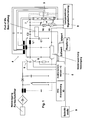
- Fig. 1 schematically shows an inventive lighting device with two lamps 1 and 2. Shown is an optional structure of the identical lighting device with only one lamp 3. Also alternative to the non-dashed design shown, a Zündsequenzkondensatoren Czs be provided, which bridges the lamp 1 for an ignition phase and initially causes the ignition of the lamp 2. In the preferred embodiment, however, the ignition sequence capacitor is absent because both a preheat transmitter 4 and an IC 5 are designed for the voltages required for two-lamp operation are.
- the IC drives a half-bridge circuit having two switches 6 and further includes power factor correction (PFC) control.
- the resonant circuit comprises a choke L1 and a capacitor C1. Furthermore, the hot lamp terminal 7 is preceded by a capacitor C2 for filtering DC components.
- the capacitances of the two capacitors C1 and C2 differ by a factor ⁇ 6 from each other, i. C2 ⁇ 6 * C1.
- a lamp current evaluation 8 and a leading and formed as a capacitor element Cve cable capacitances are not only compensated but overcompensated, which leads in particular at low dimming positions to a slight increase in lamp brightness and beyond to improved synchronization of the lamps.
- the element Cve is connected in parallel with a resistor 15 of a voltage divider formed from resistors 15 and 16. Via an interface 9, a desired value of the dimming operation is preset, which is compared in a control stage with the actual value of the lamp current. The resulting value is passed to a frequency determining input of the combi IC.
- the evaluation 8 When determining the lamp current actual value, in particular at low dimming positions, cable capacitances are not only compensated, but as a function of lamp voltage and operating frequency, the evaluation 8 only provides a somewhat lower value due to the use of the capacitance Cve. Accordingly, the IC adjusts until the setpoint is reached.
- the Vorstastedtrager 4 is primarily controlled lamp voltage independent across the half-bridge. In single-lamp operation, the secondary winding, which supplies the cathodes at the lamp center point LM in the double operation, remains open.
- Fig. 2 is a leading to a space-saving design of the preheating leading Vorußübertrager 4, which has a series of walls 10 from each other isolated chambers.
- the primary turns are found in the two large chambers 11 in the middle of the bobbin. This has two chambers 11 for the primary winding to increase the dielectric strength, while the secondary windings each have their own chambers. Overall, the transmitter therefore has five chambers.
- the winding for the lamp center is the chamber 12 can be seen.
- the hot spot winding is in chamber 13, while the ground potential winding is in chamber 14. Dashed lines show the resulting from the structure cable capacities.
- the capacitances of the two windings for the hot spot and ground for winding the lamp center are significantly smaller due to the large distance and are of a similar order of magnitude. It creates a sufficiently symmetrical structure, so that as uniform as possible operation of the two lamps is achieved during dimming.
- ballast By means of the ballast according to the invention, this can be stored both for single as well as for two-lamp designed, dimmable lights, which leads to advantages in both the production as well as in the storage.
- the compact design described here leads to housing sizes that correspond to those designed for Einlampen réelle classic electronic ballasts.
- Lighting equipment ie the dimmable lamps with two lamps, the same wiring of electronic ballasts and lamps used as in previous switchable lights.
Landscapes
- Circuit Arrangements For Discharge Lamps (AREA)
Applications Claiming Priority (1)
| Application Number | Priority Date | Filing Date | Title |
|---|---|---|---|
| DE202010013926U DE202010013926U1 (de) | 2010-10-06 | 2010-10-06 | Elektronisches Vorschaltgerät und Beleuchtungsgerät |
Publications (2)
| Publication Number | Publication Date |
|---|---|
| EP2448376A2 true EP2448376A2 (fr) | 2012-05-02 |
| EP2448376A3 EP2448376A3 (fr) | 2015-01-14 |
Family
ID=44763968
Family Applications (1)
| Application Number | Title | Priority Date | Filing Date |
|---|---|---|---|
| EP11184161.5A Withdrawn EP2448376A3 (fr) | 2010-10-06 | 2011-10-06 | Appareil de montage électronique et appareil d'éclairage |
Country Status (2)
| Country | Link |
|---|---|
| EP (1) | EP2448376A3 (fr) |
| DE (1) | DE202010013926U1 (fr) |
Citations (2)
| Publication number | Priority date | Publication date | Assignee | Title |
|---|---|---|---|---|
| EP0404143B1 (fr) | 1989-06-22 | 1994-09-14 | Alcatel SEL Aktiengesellschaft | Circuit pour surveiller des charges à courant alternatif dans des installations de chemin de fer |
| DE102008017513A1 (de) | 2008-04-04 | 2009-10-29 | HÜCO electronic GmbH | Elektronisches Vorschaltgerät und Beleuchtungsgerät |
Family Cites Families (8)
| Publication number | Priority date | Publication date | Assignee | Title |
|---|---|---|---|---|
| DE4425859A1 (de) * | 1994-07-21 | 1996-01-25 | Patent Treuhand Ges Fuer Elektrische Gluehlampen Mbh | Schaltungsanordnung zum Betrieb einer oder mehrerer Niederdruckentladungslampen |
| US6072282A (en) * | 1997-12-02 | 2000-06-06 | Power Circuit Innovations, Inc. | Frequency controlled quick and soft start gas discharge lamp ballast and method therefor |
| DE29722618U1 (de) * | 1997-12-21 | 1998-09-03 | Pritzel, Wolfgang, 83134 Prutting | Spezialinverter für LCD-Backlights für hohe magnetische Felder |
| US6111369A (en) * | 1998-12-18 | 2000-08-29 | Clalight Israel Ltd. | Electronic ballast |
| US6956336B2 (en) * | 2002-07-22 | 2005-10-18 | International Rectifier Corporation | Single chip ballast control with power factor correction |
| US7109668B2 (en) * | 2003-10-30 | 2006-09-19 | I.E.P.C. Corp. | Electronic lighting ballast |
| DK1851601T3 (da) * | 2004-08-12 | 2012-11-19 | Charles J Montante | Ballastenergiforsyning |
| DE102004051536A1 (de) * | 2004-10-21 | 2006-05-04 | Patent-Treuhand-Gesellschaft für elektrische Glühlampen mbH | Lampenbetriebsschaltung und Betriebsverfahren für eine Lampe mit Wirkstrommessung |
-
2010
- 2010-10-06 DE DE202010013926U patent/DE202010013926U1/de not_active Expired - Lifetime
-
2011
- 2011-10-06 EP EP11184161.5A patent/EP2448376A3/fr not_active Withdrawn
Patent Citations (2)
| Publication number | Priority date | Publication date | Assignee | Title |
|---|---|---|---|---|
| EP0404143B1 (fr) | 1989-06-22 | 1994-09-14 | Alcatel SEL Aktiengesellschaft | Circuit pour surveiller des charges à courant alternatif dans des installations de chemin de fer |
| DE102008017513A1 (de) | 2008-04-04 | 2009-10-29 | HÜCO electronic GmbH | Elektronisches Vorschaltgerät und Beleuchtungsgerät |
Also Published As
| Publication number | Publication date |
|---|---|
| DE202010013926U1 (de) | 2012-01-11 |
| EP2448376A3 (fr) | 2015-01-14 |
Similar Documents
| Publication | Publication Date | Title |
|---|---|---|
| EP1103165B1 (fr) | Ballast electronique destine a au moins une lampe a decharge basse tension | |
| EP1915036B1 (fr) | Appareil de montage destiné au fonctionnement d'au moins une lampe à décharge basse tension | |
| DE4243955B4 (de) | Vorschaltgerät für mindestens ein parallel betriebenes Gasentladungslampen-Paar | |
| DE2552981C3 (de) | Schaltungsanordnung zum Zünden und zum Betrieb wenigstens einer Gas- und/oder Dampfentladungslampe | |
| DE19708791C5 (de) | Steuerschaltung und elektronisches Vorschaltgerät mit einer derartigen Steuerschaltung | |
| EP1054579A2 (fr) | Circuit, système électrique associé ainsi que lampe à décharge avec un tel circuit et son procédé d'alimentation | |
| EP1653785B1 (fr) | Dispositif d'allumage pour une lampe a decharge haute pression et une lampe a décharge haute pression avec un dispositif d'allumage et méthode d'opération. | |
| DE3338464C2 (de) | Schaltungsanordnung zum Betrieb mindestens einer Leuchtstofflampe mit einstellbarer Helligkeit an einem selbstschwingenden Wechselrichter | |
| DE60122192T2 (de) | Schaltungsanordnung | |
| EP1836882B1 (fr) | Ballast electronique | |
| EP1276355B1 (fr) | Circuit ballast pour determiner la puissance de préchauffage | |
| EP2448376A2 (fr) | Appareil de montage électronique et appareil d'éclairage | |
| DE10252836A1 (de) | Vorrichtung zum Betreiben von Entlaudungslampen | |
| EP1771045B1 (fr) | Circuit d' amorçage pour une lampe à décharge haute-pression | |
| DE10127135B4 (de) | Dimmbares elektronisches Vorschaltgerät | |
| DE102004009995A1 (de) | Schaltungsanordnung und Verfahren zum Betreiben einer Gasentladungslampe mit einem Heiztransformator | |
| AT505376B1 (de) | Steuerschaltung für leuchtmittel-betriebsgeräte | |
| DE10226899A1 (de) | Vorrichtung zum Betreiben von Entladungslampen | |
| WO1998009483A1 (fr) | Allast electronique pour lampes a decharge | |
| DE10304544A1 (de) | Elektronisches Vorschaltgerät | |
| DE4245092B4 (de) | Vorschaltgerät für mindestens ein parallel betriebenes Gasentladungslampen-Paar | |
| EP0845927B1 (fr) | Circuit pour alimenter une lampe à décharge basse pression par une source à basse tension | |
| DE10203356B4 (de) | Vorschaltgerät für Kaltkathoden-Fluoreszenzlampen | |
| DE102005030007B4 (de) | Verfahren zum Vorheizen einer Anzahl von Heizwendeln | |
| EP1294215A2 (fr) | Ballast pour au moins une lampe à incandescence |
Legal Events
| Date | Code | Title | Description |
|---|---|---|---|
| PUAI | Public reference made under article 153(3) epc to a published international application that has entered the european phase |
Free format text: ORIGINAL CODE: 0009012 |
|
| AK | Designated contracting states |
Kind code of ref document: A2 Designated state(s): AL AT BE BG CH CY CZ DE DK EE ES FI FR GB GR HR HU IE IS IT LI LT LU LV MC MK MT NL NO PL PT RO RS SE SI SK SM TR |
|
| AX | Request for extension of the european patent |
Extension state: BA ME |
|
| RIN1 | Information on inventor provided before grant (corrected) |
Inventor name: HONERKAMP, STEFAN |
|
| RAP1 | Party data changed (applicant data changed or rights of an application transferred) |
Owner name: BAG ENGINEERING GMBH |
|
| PUAL | Search report despatched |
Free format text: ORIGINAL CODE: 0009013 |
|
| AK | Designated contracting states |
Kind code of ref document: A3 Designated state(s): AL AT BE BG CH CY CZ DE DK EE ES FI FR GB GR HR HU IE IS IT LI LT LU LV MC MK MT NL NO PL PT RO RS SE SI SK SM TR |
|
| AX | Request for extension of the european patent |
Extension state: BA ME |
|
| RIC1 | Information provided on ipc code assigned before grant |
Ipc: H05B 41/295 20060101AFI20141208BHEP Ipc: H05B 41/39 20060101ALI20141208BHEP Ipc: H05B 41/392 20060101ALI20141208BHEP |
|
| STAA | Information on the status of an ep patent application or granted ep patent |
Free format text: STATUS: THE APPLICATION IS DEEMED TO BE WITHDRAWN |
|
| 18D | Application deemed to be withdrawn |
Effective date: 20150501 |