EP2448794B1 - Kraftfahrzeuggetriebe mit hydrodynamischem retarder - Google Patents
Kraftfahrzeuggetriebe mit hydrodynamischem retarder Download PDFInfo
- Publication number
- EP2448794B1 EP2448794B1 EP10723586A EP10723586A EP2448794B1 EP 2448794 B1 EP2448794 B1 EP 2448794B1 EP 10723586 A EP10723586 A EP 10723586A EP 10723586 A EP10723586 A EP 10723586A EP 2448794 B1 EP2448794 B1 EP 2448794B1
- Authority
- EP
- European Patent Office
- Prior art keywords
- shaft
- clutch
- power take
- gearbox
- power takeoff
- Prior art date
- Legal status (The legal status is an assumption and is not a legal conclusion. Google has not performed a legal analysis and makes no representation as to the accuracy of the status listed.)
- Not-in-force
Links
Images

Classifications
-
- B—PERFORMING OPERATIONS; TRANSPORTING
- B60—VEHICLES IN GENERAL
- B60T—VEHICLE BRAKE CONTROL SYSTEMS OR PARTS THEREOF; BRAKE CONTROL SYSTEMS OR PARTS THEREOF, IN GENERAL; ARRANGEMENT OF BRAKING ELEMENTS ON VEHICLES IN GENERAL; PORTABLE DEVICES FOR PREVENTING UNWANTED MOVEMENT OF VEHICLES; VEHICLE MODIFICATIONS TO FACILITATE COOLING OF BRAKES
- B60T10/00—Control or regulation for continuous braking making use of fluid or powdered medium, e.g. for use when descending a long slope
- B60T10/02—Control or regulation for continuous braking making use of fluid or powdered medium, e.g. for use when descending a long slope with hydrodynamic brake
Definitions
- the invention relates to a transmission of a motor vehicle with hydrodynamic retarder according to the preamble of claim 1 and a method for operating the transmission according to the preamble of claim 11.
- Motor vehicles with a retarder as a hydrodynamic brake are known, with primary and secondary retarders being different: primary retarders are located on the engine side and secondary retarders on the transmission side in the drive train. Secondary retarders are flanged to the transmission or integrated into the transmission housing and driven by the transmission output shaft via a high-powered stage. It is also known to provide transmission with a connection for a power take-off, wherein this connection is operated clutch-dependent, d. H. when the internal combustion engine of the motor vehicle is running and the clutch between the engine and transmission is closed - in this case, the connection for the power take-off can be put into operation.
- the applicant was a motor vehicle transmission with a hydrodynamic retarder known, which is connected via an angle drive to the output shaft of the transmission.
- the known transmission has a drive shaft, a main shaft and two countershafts, wherein in the drawing in extension of the upper countershaft another shaft is shown, which can be regarded as a drive shaft for a power take-off.
- At least one further power take-off can be driven by the drive gear, the so-called high-drive gear of the high-drive stage. This is done via another pinion, which - in addition to the pinion for driving the retarder - with the high-drive gear is in Zahnreingriff.
- the transmission has a connection for another power take-off, which is housed in the smallest space.
- the further output gear or the second pinion is arranged on a pinion shaft driving a power take-off shaft.
- a clutch is arranged between the power take-off shaft for the further power take-off and the pinion shaft through which the power take-off shaft with the pinion shaft can be coupled, d. H. the additional power take-off can be switched on or off via the first clutch.
- the additional power take-off operation is dependent on the driving, d. H. when the vehicle is driving.
- the further power take-off is connected via a spur gear with an additional power take-off. This results in a connection for an additional PTO, the translation is preferably carried out quickly.
- the power take-off shaft is via a further spur gear and a second clutch with the power take-off coupled.
- the further spur gear may comprise an intermediate gear, whereby the direction of rotation is reversible, so that the further and the power take-off in the same direction of rotation.
- the power take-off via a transmission shaft, preferably a countershaft is driven, wherein in the power take-off a third clutch is.
- the power take-off can be switched on the one hand and thus operated clutch-dependent or decoupled from the transmission shaft and driven dependent on the other power take-off.
- a mechanical, electrical or electronic control unit is provided, which monitors the switching state of the first, second and third clutch.
- the power take-offs are operable in a clutch-dependent or driving-dependent or clutch-dependent and driving-dependent manner.
- the clutches By operating the clutches on the electronic control unit, the PTOs can be switched so that they can be operated on the one hand with the vehicle and the engine running and on the other hand when the vehicle or stationary and moving vehicle.
- Fig. 1 shows the output side part of a transmission 1, which has a main shaft 2, two countershafts 3, 4 and an output shaft 5 with output flange 6.
- the transmission 1, which is not completely illustrated, essentially corresponds to the transmission of the cited document DE 101 56 186 A1 .
- the main shaft 2 is connected to the output shaft 5 via a planetary gear 7, which is switchable by a switching device 8 in different gear ratios.
- a drive gear 9 is rotatably disposed, which is in engagement with a driven gear 10 and forms a spur gear 11 for driving a retarder 12.
- the drive gear 9 is also referred to as Hochtreiberrad 9 and the spur gear 11 as Hochtreiberlace 11 or 11 high-drive, since the drive of the retarder 12 is done quickly.
- the Hochtreiberrad 9 is in engagement with a further output gear 13, which is also referred to as a power take-off pinion 13.
- the power take-off pinion 13 drives a pinion shaft 14, which can be connected via a first clutch 15 with a power take-off shaft 16 or separated from it.
- the power take-off shaft 16 has a connection 17 which can be connected to a further power take-off, not shown.
- the power take-off shaft 16 drives via a spur gear 18/19 an additional power take-off shaft 20 with a connection 21 for an additional power take-off, not shown.
- the power take-off shaft 16 is connected to a power take-off shaft 22, which has a connection 23 for a power take-off, not shown.
- the power take-off shaft 22 is driven via the gears 18, 24, 25 and can be connected via a second clutch 26.
- the gear 24 is formed as an intermediate, so that the ports 17, 23 for the power take-offs have the same direction of rotation.
- the power take-off shaft 22 can be connected via a third clutch 27 with the countershaft 3, also called gear shaft 3, the transmission 1. This results in an additional drive possibility for the terminal 23, which is 26 clutch-dependent operable when the third clutch 27 and the second open clutch 26 is closed.
- the switching state of the first, second, third clutch, 15, 26, 27 is monitored by a control unit 28, which is indicated by dotted signal lines.
- the three power take-offs 17, 21, 23 are operated as follows: The power take-offs 17, 21 can be operated on the one hand drove, then the clutch 15 is closed and the clutch 26 open. On the other hand, the power take-offs 17, 20 are operated clutch-dependent, then the clutch 15 is open, and the clutches 26, 27 are closed.
- the power take-off 23 can be operated in a clutch-dependent manner by closing the shift clutch 27 and by driving the clutch 27 and closing the clutches 26, 15.
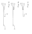
- Fig. 1a, 1b, 1c show three different ways of power flow during operation of the three power take offs or terminals 23, 17, 21, which are numbered from top to bottom.
- Fig. 1 a shows an upper continuous line to the power take-off 23, ie when the clutch 27 and open clutch 26 is closed, a through drive from the countershaft 3 to the port 23. At the same time, the clutch 15 is closed, so that the power take-offs 17, 21 are operated drove.
- Fig. 1b shows the power flow with closed clutches 27, 26 and open clutch 15, ie all three power take-offs 23, 17, 21 are operated clutch-dependent.
- Fig. 1c shows the power flow with open clutch 27 and closed clutch 15, ie the drive of the three power take-offs 23, 17, 21 is dependent on the driving.
Landscapes
- Engineering & Computer Science (AREA)
- Physics & Mathematics (AREA)
- Fluid Mechanics (AREA)
- Transportation (AREA)
- Mechanical Engineering (AREA)
- Structure Of Transmissions (AREA)
Description
- Die Erfindung betrifft ein Getriebe eines Kraftfahrzeuges mit hydrodynamischem Retarder nach dem Oberbegriff des Patentanspruches 1 sowie ein Verfahren zum Betreiben des Getriebes nach dem Oberbegriff des Patentanspruches 11.
- Kraftfahrzeuge mit Retarder als hydrodynamischer Bremse sind bekannt, wobei man Primär- und Sekundärretarder unterscheidet: Primärretarder befinden sich motorseitig und Sekundärretarder getriebeseitig im Triebstrang. Sekundärretarder werden an das Getriebe angeflanscht oder in das Getriebegehäuse integriert und von der Getriebeabtriebswelle über eine Hochtriebstufe angetrieben. Bekannt ist es auch, Getriebe mit einem Anschluss für einen Nebenabtrieb auszustatten, wobei dieser Anschluss kupplungsabhängig betreibbar ist, d. h. wenn die Brennkraftmaschine des Kraftfahrzeuges läuft und die Kupplung zwischen Brennkraftmaschine und Getriebe geschlossen ist - in diesem Falle kann der Anschluss für den Nebenabtrieb in Betrieb genommen werden.
- Durch die
DE 101 56 186 A1 , siehe Oberbegriff des Anspruchs 1, der Anmelderin wurde ein Kraftfahrzeuggetriebe mit einem hydrodynamischen Retarder bekannt, welcher über einen Winkeltrieb an die Abtriebswelle des Getriebes angeschlossen ist. Das bekannte Getriebe weist eine Antriebswelle, eine Hauptwelle und zwei Vorgelegewellen auf, wobei in der Zeichnung in Verlängerung der oberen Vorgelegewelle eine weitere Welle dargestellt ist, die als Antriebswelle für einen Nebenabtrieb angesehen werden kann. - Durch die
DE 41 08 658 A1 der Anmelderin wurde ein Kraftfahrzeuggetriebe mit einem hydrodynamischen Retarder bekannt, welcher von der Abtriebswelle des Getriebes über eine Stirnradstufe, einer so genannten Hochtreiberstufe, angetrieben wird. - Es ist Aufgabe der vorliegenden Erfindung, bei einem Getriebe der eingangs genannten Art mindestens einen weiteren Anschluss für einen Nebenabtrieb zu schaffen, der möglichst vielfältig verwendbar sein soll. Es ist auch Aufgabe der Erfindung, ein Verfahren zum Betreiben des Getriebes, insbesondere für unterschiedliche Verwendungen der Nebenabtriebe bereitzustellen.
- Die Aufgabe der Erfindung wird durch die Merkmale der unabhängigen Patentansprüche 1 und 11 gelöst. Vorteilhafte Ausgestaltungen ergeben sich aus den Unteransprüchen.
- Erfindungsgemäß ist vorgesehen, dass von dem Antriebszahnrad, dem so genannten Hochtreiberrad der Hochtreiberstufe, mindestens ein weiterer Nebenabtrieb antreibbar ist. Dies erfolgt über ein weiteres Ritzel, welches - zusätzlich zu dem Ritzel für den Antrieb des Retarders - mit dem Hochtreiberrad in Zahnreingriff steht. Damit wird der Vorteil erreicht, dass das Getriebe über einen Anschluss für einen weiteren Nebenabtrieb verfügt, welcher auf geringstem Bauraum untergebracht ist.
- Nach einer bevorzugten Ausführungsform ist das weitere Abtriebszahnrad bzw. das zweite Ritzel auf einer eine Nebenabtriebswelle antreibenden Ritzelwelle angeordnet.
- Nach einer weiteren bevorzugten Ausführungsform ist zwischen der Nebenabtriebswelle für den weiteren Nebenabtrieb und der Ritzelwelle eine Schaltkupplung angeordnet, durch welche die Nebenabtriebswelle mit der Ritzelwelle kuppelbar ist, d. h. der weitere Nebenabtrieb kann über die erste Schaltkupplung zu- oder abgeschaltet werden. Bei Zuschaltung des weiteren Nebenabtriebes erfolgt der Betrieb fahrabhängig, d. h. wenn das Fahrzeug fährt.
- Nach einer weiteren bevorzugten Ausführungsform ist der weitere Nebenabtrieb über eine Stirnradstufe mit einem zusätzlichen Nebenabtrieb verbunden. Damit ergibt sich ein Anschluss für einen zusätzlichen Nebenabtrieb, wobei die Übersetzung vorzugsweise ins Schnelle erfolgt.
- Nach einer weiteren bevorzugten Ausführungsform ist die Nebenabtriebswelle über eine weitere Stirnradstufe und eine zweite Schaltkupplung mit dem Nebenabtrieb kuppelbar. Alternativ kann die weitere Stirnradstufe ein Zwischenrad umfassen, wodurch die Drehrichtung umkehrbar ist, sodass der weitere und der Nebenabtrieb in derselben Drehrichtung umlaufen.
- Nach einer weiteren bevorzugten Ausführungsform ist der Nebenabtrieb über eine Getriebewelle, vorzugsweise eine Vorgelegewelle antreibbar, wobei sich im Nebenabtriebsstrang eine dritte Schaltkupplung befindet. Dadurch kann der Nebenabtrieb einerseits zugeschaltet und damit kupplungsabhängig betrieben werden oder von der Getriebewelle abgekoppelt und fahrabhängig über den weiteren Nebenabtrieb betrieben werden.
- Nach einer weiteren bevorzugten Ausführungsform ist eine mechanische, elektrische oder elektronische Kontrolleinheit vorgesehen, welche den Schaltzustand der ersten, zweiten und dritten Schaltkupplung überwacht. Damit können unterschiedliche Betriebs- und Schaltzustände der drei Nebenabtriebe eingeleitet und kontrolliert werden.
- Erfindungsgemäß ist bei einem Verfahren zum Betreiben des Getriebes vorgesehen, dass die Nebenabtriebe kupplungsabhängig oder fahrabhängig oder kupplungs- und fahrabhängig betreibbar sind. Durch Betätigung der Schaltkupplungen über die elektronische Kontrolleinheit können die Nebenabtriebe so geschaltet werden, dass sie einerseits bei stehendem Fahrzeug und laufendem Motor und andererseits bei fahrendem Fahrzeug oder bei stehendem und fahrendem Fahrzeug betrieben werden können.
- Ein Ausführungsbeispiel der Erfindung ist in der Zeichnung dargestellt und wird im Folgenden näher beschrieben, wobei sich aus der Beschreibung und/oder der Zeichnung weitere Merkmale und/oder Vorteile ergeben können. Es zeigen
- Fig. 1
- ein Getriebe mit Anschlüssen für Nebenabtriebe und
- Fig. 1 a, 1 b, 1 c
- ein Schema für den Kraftfluss beim Betrieb der Nebenabtriebe.
-
Fig. 1 zeigt den abtriebsseitigen Teil eines Getriebe 1, welches eine Hauptwelle 2, zwei Vorgelegewellen 3, 4 sowie eine Abtriebswelle 5 mit Abtriebsflansch 6 aufweist. Das nicht vollständig dargestellte Getriebe 1 entspricht im Wesentlichen dem Getriebe der eingangs genannten DruckschriftDE 101 56 186 A1 . Die Hauptwelle 2 ist mit der Abtriebswelle 5 über einen Planetenradsatz 7 verbunden, welcher durch eine Schalteinrichtung 8 in unterschiedliche Übersetzungsstufen schaltbar ist. Auf der Abtriebswelle 5 ist ein Antriebszahnrad 9 drehfest angeordnet, welches mit einem Abtriebszahnrad 10 in Eingriff steht und eine Stirnradstufe 11 zum Antrieb eines Retarders 12 bildet. Das Antriebszahnrad 9 wird auch als Hochtreiberrad 9 und die Stirnradstufe 11 auch als Hochtreiberstufe 11 oder Hochtrieb 11 bezeichnet, da der Antrieb des Retarders 12 ins Schnelle erfolgt. - Erfindungsgemäß steht das Hochtreiberrad 9 mit einem weiteren Abtriebszahnrad 13 in Eingriff, welches auch als Nebenabtriebsritzel 13 bezeichnet wird. Das Nebenabtriebsritzel 13 treibt eine Ritzelwelle 14 an, welche über eine erste Schaltkupplung 15 mit einer Nebenabtriebswelle 16 verbunden oder von dieser getrennt werden kann. Die Nebenabtriebswelle 16 weist einen Anschluss 17 auf, der mit einem nicht dargestellten weiteren Nebenabtrieb verbunden werden kann. Die Nebenabtriebswelle 16 treibt über eine Stirnradstufe 18/19 eine zusätzliche Nebenabtriebswelle 20 mit einem Anschluss 21 für einen nicht dargestellten zusätzlichen Nebenabtrieb an. Die Nebenabtriebswelle 16 steht mit einer Nebenabtriebswelle 22 in Verbindung, welche einen Anschluss 23 für einen nicht dargestellten Nebenabtrieb aufweist. Die Nebenabtriebswelle 22 wird über die Zahnräder 18, 24, 25 angetrieben und ist über eine zweite Schaltkupplung 26 zuschaltbar. Das Zahnrad 24 ist als Zwischenrad ausgebildet, sodass die Anschlüsse 17, 23 für die Nebenabtriebe die gleiche Drehrichtung aufweisen. Die Nebenabtriebswelle 22 kann über eine dritte Schaltkupplung 27 mit der Vorgelegewelle 3, auch Getriebewelle 3 genannt, des Getriebes 1 verbunden werden. Dadurch ergibt sich eine zusätzliche Antriebsmöglichkeit für den Anschluss 23, welcher bei geschlossener dritter Schaltkupplung 27 und geöffneter zweiter Schaltkupplung 26 kupplungsabhängig betreibbar ist. Der Schaltzustand der ersten, zweiten, dritten Schaltkupplung, 15, 26, 27 wird durch eine Kontrolleinheit 28 überwacht, was durch punktierte Signalleitungen angedeutet ist.
- Die drei Nebenabtriebe 17, 21, 23 sind wie folgt betreibbar: Die Nebenabtriebe 17, 21 können einerseits fahrabhängig betrieben werden, dann ist die Schaltkupplung 15 geschlossen und die Schaltkupplung 26 offen. Andererseits können die Nebenabtriebe 17, 20 kupplungsabhängig betrieben werden, dann ist die Schaltkupplung 15 offen, und die Schaltkupplungen 26, 27 sind geschlossen.
- Ferner kann der Nebenabtrieb 23 durch Schließen der Schaltkupplung 27 kupplungsabhängig und durch Öffnen der Schaltkupplung 27 und Schließen der Schaltkupplungen 26, 15 fahrabhängig betrieben werden.
-
Fig. 1a, 1b, 1c zeigen drei verschiedene Möglichkeiten des Kraftflusses beim Betrieb der drei Nebenabtriebe bzw. Anschlüsse 23, 17, 21, die jeweils von oben nach unten durchnummeriert sind.Fig. 1 a zeigt eine obere durchgehende Linie zum Nebenabtrieb 23, d. h. bei geschlossener Schaltkupplung 27 und offener Schaltkupplung 26 erfolgt ein Durchtrieb von der Vorgelegewelle 3 auf den Anschluss 23. Gleichzeitig ist die Schaltkupplung 15 geschlossen, sodass die Nebenabtriebe 17, 21 fahrabhängig betrieben werden. -
Fig. 1b zeigt den Kraftfluss bei geschlossenen Schaltkupplungen 27, 26 und geöffneter Schaltkupplung 15, d. h. alle drei Nebenabtriebe 23, 17, 21 werden kupplungsabhängig betrieben. -
Fig. 1c zeigt den Kraftfluss bei geöffneter Schaltkupplung 27 und geschlossener Schaltkupplung 15, d. h. der Antrieb der drei Nebenabtriebe 23, 17, 21 erfolgt fahrabhängig. -
- 1
- Getriebe
- 2
- Hauptwelle
- 3
- Vorgelegewelle
- 4
- Vorgelegewelle
- 5
- Abtriebswelle
- 6
- Abtriebsflansch
- 7
- Planetenradsatz
- 8
- Schalteinrichtung
- 9
- Antriebszahnrad (Hochtreiberrad)
- 10
- Abtriebszahnrad
- 11
- Stirnradstufe (Hochtreiberstufe)
- 12
- Retarder
- 13
- weiteres Abtriebszahnrad (Nebenabtriebsritzel)
- 14
- Ritzelwelle
- 15
- erste Schaltkupplung
- 16
- Nebenabtriebswelle
- 17
- Anschluss für weiteren Nebenabtrieb
- 18
- Zahnrad
- 19
- Zahnrad
- 20
- Nebenabtriebswelle
- 21
- Anschluss für zusätzlichen Nebenabtrieb
- 22
- Nebenabtriebswelle
- 23
- Anschluss für Nebenabtrieb
- 24
- Zwischenrad
- 25
- Zahnrad
- 26
- zweite Schaltkupplung
- 27
- dritte Schaltkupplung
- 28
- Kontrolleinheit
Claims (11)
- Getriebe eines Kraftfahrzeuges mit hydrodynamischem Retarder (12) und mindestens einem Anschluss (23) für einen Nebenabtrieb, wobei der Retarder (12) von einer Abtriebswelle (5) des Getriebes (1) über eine ein Antriebszahnrad (9) und ein Abtriebszahnrad (10) aufweisende Stirnradstufe (11) antreibbar ist, dadurch gekennzeichnet, dass das Antriebszahnrad (9) mit mindestens einem weiteren Abtriebszahnrad (13) in Eingriff steht, durch welches mindestens ein weiterer Nebenabtrieb (17, 21) antreibbar ist.
- Getriebe nach Anspruch 1, dadurch gekennzeichnet, dass das weitere Abtriebszahnrad (13) auf einer Ritzelwelle (14) angeordnet ist.
- Getriebe nach Anspruch 2, dadurch gekennzeichnet, dass die Ritzelwelle (14) mit einer Nebenabtriebswelle (16) kuppelbar ist, die abtriebsseitig einen Anschluss (17) für den weiteren Nebenabtrieb aufweist.
- Getriebe nach Anspruch 2 oder 3, dadurch gekennzeichnet, dass die Nebenabtriebswelle (16) mittels einer ersten Schaltkupplung (15) trennbar oder zuschaltbar ist.
- Getriebe nach Anspruch 2, 3 oder 4, dadurch gekennzeichnet, dass die Nebenabtriebswelle (16) über eine Stirnradstufe (18, 19) mit einer zusätzlichen Nebenabtriebswelle (20) verbunden ist.
- Getriebe nach einem der Ansprüche 2 bis 5, dadurch gekennzeichnet, dass die Nebenabtriebswelle (16) über eine Stirnradstufe (18, 24, 25) und eine zweite Schaltkupplung (26) mit dem Nebenabtrieb (23) kuppelbar ist.
- Getriebe nach Anspruch 6, dadurch gekennzeichnet, dass die Stirnradstufe (18, 25) ein Zwischenrad (24) umfasst.
- Getriebe nach einem der Ansprüche 1 bis 7, dadurch gekennzeichnet, dass der Nebenabtrieb (23) von einer Getriebewelle oder Vorgelegewelle (3) des Getriebes (1) antreibbar ist.
- Getriebe nach Anspruch 8, dadurch gekennzeichnet, dass der Nebenabtrieb (23) über eine dritte Schaltkupplung (27) zuschaltbar ist.
- Getriebe nach einem der Ansprüche 1 bis 9, dadurch gekennzeichnet, dass eine mechanische, elektrische oder elektronische Kontrolleinheit (28) für die Überwachung der Schaltzustände der Schaltkupplungen (15, 26, 27) vorgesehen ist.
- Verfahren zum Betreiben eines Getriebes (1) mit Nebenabtrieben (17, 21, 23) nach einem der vorhergehenden Ansprüche, dadurch gekennzeichnet, dass sämtliche Nebenabtriebe (17, 21, 23) kupplungsabhängig oder fahrabhängig oder kupplungs- und fahrabhängig betrieben sind.
Applications Claiming Priority (2)
| Application Number | Priority Date | Filing Date | Title |
|---|---|---|---|
| DE102009027390A DE102009027390A1 (de) | 2009-07-01 | 2009-07-01 | Kraftfahrzeuge mit hydrodynamischem Retarder |
| PCT/EP2010/057881 WO2011000664A1 (de) | 2009-07-01 | 2010-06-07 | Kraftfahrzeuggetriebe mit hydrodynamischem retarder |
Publications (2)
| Publication Number | Publication Date |
|---|---|
| EP2448794A1 EP2448794A1 (de) | 2012-05-09 |
| EP2448794B1 true EP2448794B1 (de) | 2013-03-13 |
Family
ID=42556713
Family Applications (1)
| Application Number | Title | Priority Date | Filing Date |
|---|---|---|---|
| EP10723586A Not-in-force EP2448794B1 (de) | 2009-07-01 | 2010-06-07 | Kraftfahrzeuggetriebe mit hydrodynamischem retarder |
Country Status (5)
| Country | Link |
|---|---|
| US (1) | US8573376B2 (de) |
| EP (1) | EP2448794B1 (de) |
| CN (1) | CN102470829B (de) |
| DE (1) | DE102009027390A1 (de) |
| WO (1) | WO2011000664A1 (de) |
Families Citing this family (4)
| Publication number | Priority date | Publication date | Assignee | Title |
|---|---|---|---|---|
| DE102010051715A1 (de) * | 2010-11-19 | 2012-05-24 | Voith Patent Gmbh | Antriebsstrang mit einem hydrodynamischen Retarder |
| DE102011120619A1 (de) * | 2011-12-09 | 2013-06-13 | Voith Patent Gmbh | Kraftfahrzeugantriebsstrang mit einem hydrodynamischen Retarder |
| DE102013224028A1 (de) * | 2013-11-25 | 2015-05-28 | Zf Friedrichshafen Ag | Kraftfahrzeuggetriebe für ein Nutzfahrzeug |
| CN110307303A (zh) * | 2019-06-06 | 2019-10-08 | 丰疆智能科技研究院(常州)有限公司 | 农业机械 |
Family Cites Families (14)
| Publication number | Priority date | Publication date | Assignee | Title |
|---|---|---|---|---|
| DE2656669B1 (de) * | 1976-12-15 | 1978-03-09 | Zahnradfabrik Friedrichshafen | Lastschaltgetriebe mit einer hydrodynamischen Einheit und einem hydrodynamischen Retarder |
| DE3536928A1 (de) * | 1984-10-24 | 1986-04-30 | Zahnradfabrik Friedrichshafen | Antriebsanordnung fuer nutzkraftfahrzeuge |
| DE3837142A1 (de) | 1987-11-05 | 1989-05-18 | Zahnradfabrik Friedrichshafen | Kraftfahrzeug mit einem einem zahnraederwechselgetriebe nachgeschalteten hydrodynamischen retarder |
| DE4108658C2 (de) | 1991-03-16 | 2001-12-06 | Zahnradfabrik Friedrichshafen | Kraftfahrzeug mit einem einem Zahnräderwechselgetriebe nachgeschalteten, hydrodynamischen Retarder |
| DE4306743A1 (de) | 1993-03-04 | 1994-09-08 | Zahnradfabrik Friedrichshafen | Antriebsanordnung für Nutzkraftfahrzeuge |
| DE4324460C1 (de) * | 1993-07-21 | 1994-11-24 | Daimler Benz Ag | Zahnräderwechselgetriebe für Kraftfahrzeuge mit einer Dauerbremse (Sekundärretarder) |
| US5661998A (en) * | 1996-02-06 | 1997-09-02 | Eaton Corporation | Three-position actuator piston assembly and actuator system utilizing same |
| DE19751776A1 (de) | 1997-11-21 | 1999-05-27 | Zahnradfabrik Friedrichshafen | Retarder für Getriebe von Nutzfahrzeugen |
| DE19817865A1 (de) * | 1998-04-22 | 1999-10-28 | Zahnradfabrik Friedrichshafen | Getriebe mit Retarder |
| DE19837776A1 (de) * | 1998-08-20 | 2000-02-24 | Zahnradfabrik Friedrichshafen | Getriebe mit nicht-koaxialem Abtrieb |
| DE10156186A1 (de) | 2001-11-15 | 2003-06-05 | Zahnradfabrik Friedrichshafen | Hydrodynamischer Retarder |
| US20050241423A1 (en) * | 2004-04-28 | 2005-11-03 | Muetzel Ronald P | Inertia brake controls |
| DE102006002968A1 (de) * | 2006-01-21 | 2007-08-16 | Zf Friedrichshafen Ag | Zahnräderwechselgetriebe mit einem nachgeschalteten, konstant übersetzten Zusatzantrieb |
| DE102006050009A1 (de) | 2006-10-24 | 2008-04-30 | Zf Friedrichshafen Ag | Getriebebremseneinrichtung für ein mehrstufiges Schaltgetriebe |
-
2009
- 2009-07-01 DE DE102009027390A patent/DE102009027390A1/de not_active Withdrawn
-
2010
- 2010-06-07 WO PCT/EP2010/057881 patent/WO2011000664A1/de not_active Ceased
- 2010-06-07 EP EP10723586A patent/EP2448794B1/de not_active Not-in-force
- 2010-06-07 CN CN201080029717.9A patent/CN102470829B/zh not_active Expired - Fee Related
- 2010-06-07 US US13/378,559 patent/US8573376B2/en not_active Expired - Fee Related
Also Published As
| Publication number | Publication date |
|---|---|
| EP2448794A1 (de) | 2012-05-09 |
| CN102470829B (zh) | 2015-03-11 |
| CN102470829A (zh) | 2012-05-23 |
| US8573376B2 (en) | 2013-11-05 |
| DE102009027390A1 (de) | 2011-01-05 |
| US20120138418A1 (en) | 2012-06-07 |
| WO2011000664A1 (de) | 2011-01-06 |
Similar Documents
| Publication | Publication Date | Title |
|---|---|---|
| EP4155578B1 (de) | Antriebseinrichtung für einen kraftfahrzeugantriebsstrang eines elektrofahrzeugs | |
| DE102019107538A1 (de) | Torque-Vectoring-Getriebe für ein Kraftfahrzeug | |
| EP1714818B1 (de) | Doppelkupplungsgetriebe | |
| EP3870879A1 (de) | Lastschaltbares mehrganggetriebe | |
| DE102011110258A1 (de) | Getriebe | |
| DE102013200646A1 (de) | Verfahren zum Schalten eines in Gruppenbauweise ausgeführten Kraftfahrzeug-getriebes, sowie Kraftfahrzeuggetriebe in Gruppenbauweise | |
| EP1387967A1 (de) | Getriebebaukasten | |
| EP3091253A1 (de) | Getriebeanordnung | |
| EP2078884B1 (de) | Automatgetriebe eines Kraftfahrzeuges | |
| DE19813622A1 (de) | Verfahren und Einrichtung zur lastschaltbaren Umschaltung eines hydrostatischen Fahrantriebes einer mobilen Baumaschine | |
| DE19858124C2 (de) | Radantrieb | |
| WO2011000664A1 (de) | Kraftfahrzeuggetriebe mit hydrodynamischem retarder | |
| WO2018104043A1 (de) | 6-gang-planetenradgetriebe | |
| DE102011119833B4 (de) | Schaltvorrichtung für Doppelkupplungsgetriebe in Kraftfahrzeugen | |
| EP1629222B1 (de) | Vorrichtung zur steuerung eines automatikgetriebes | |
| DE102018111870A1 (de) | Elektrische Antriebseinheit mit schaltbarem Getriebe | |
| DE2904062A1 (de) | Flaches automatisches getriebe | |
| EP3808587B1 (de) | Verfahren zur deaktivierung eines parksperrenmechanismus eines hybridantriebsstrangs für ein kraftfahrzeug | |
| DE102011016661A1 (de) | Doppelkupplungsgetriebe und Verfahren zu dessen Betreiben | |
| DE19708930B4 (de) | Steuerung von Nebenabtrieben in automatisierten Fahrzeuggetrieben | |
| DE102017216231A1 (de) | Antriebseinheit für ein Kraftfahrzeug, Kraftfahrzeug sowie Verfahren zum Betrieb einer Antriebseinheit | |
| DE102017209414A1 (de) | Getriebevorrichtung für einen Kraftwagen und Verfahren zum Betreiben einer Getriebevorrichtung | |
| WO2018091235A1 (de) | Getriebe, insbesondere kraftfahrzeuggetriebe, sowie antriebsstrang | |
| DE10230185A1 (de) | Bauelement für den Abtriebsstrang eines Kraftfahrzeugs | |
| WO2015043694A1 (de) | Drehmomentübertragungsvorrichtung für ein kraftfahrzeug |
Legal Events
| Date | Code | Title | Description |
|---|---|---|---|
| PUAI | Public reference made under article 153(3) epc to a published international application that has entered the european phase |
Free format text: ORIGINAL CODE: 0009012 |
|
| 17P | Request for examination filed |
Effective date: 20111206 |
|
| AK | Designated contracting states |
Kind code of ref document: A1 Designated state(s): AL AT BE BG CH CY CZ DE DK EE ES FI FR GB GR HR HU IE IS IT LI LT LU LV MC MK MT NL NO PL PT RO SE SI SK SM TR |
|
| DAX | Request for extension of the european patent (deleted) | ||
| GRAP | Despatch of communication of intention to grant a patent |
Free format text: ORIGINAL CODE: EPIDOSNIGR1 |
|
| GRAS | Grant fee paid |
Free format text: ORIGINAL CODE: EPIDOSNIGR3 |
|
| GRAA | (expected) grant |
Free format text: ORIGINAL CODE: 0009210 |
|
| AK | Designated contracting states |
Kind code of ref document: B1 Designated state(s): AL AT BE BG CH CY CZ DE DK EE ES FI FR GB GR HR HU IE IS IT LI LT LU LV MC MK MT NL NO PL PT RO SE SI SK SM TR |
|
| REG | Reference to a national code |
Ref country code: GB Ref legal event code: FG4D Free format text: NOT ENGLISH |
|
| REG | Reference to a national code |
Ref country code: AT Ref legal event code: REF Ref document number: 600600 Country of ref document: AT Kind code of ref document: T Effective date: 20130315 Ref country code: CH Ref legal event code: EP |
|
| REG | Reference to a national code |
Ref country code: IE Ref legal event code: FG4D Free format text: LANGUAGE OF EP DOCUMENT: GERMAN |
|
| REG | Reference to a national code |
Ref country code: DE Ref legal event code: R096 Ref document number: 502010002554 Country of ref document: DE Effective date: 20130508 |
|
| REG | Reference to a national code |
Ref country code: SE Ref legal event code: TRGR |
|
| PG25 | Lapsed in a contracting state [announced via postgrant information from national office to epo] |
Ref country code: LT Free format text: LAPSE BECAUSE OF FAILURE TO SUBMIT A TRANSLATION OF THE DESCRIPTION OR TO PAY THE FEE WITHIN THE PRESCRIBED TIME-LIMIT Effective date: 20130313 Ref country code: NO Free format text: LAPSE BECAUSE OF FAILURE TO SUBMIT A TRANSLATION OF THE DESCRIPTION OR TO PAY THE FEE WITHIN THE PRESCRIBED TIME-LIMIT Effective date: 20130613 Ref country code: ES Free format text: LAPSE BECAUSE OF FAILURE TO SUBMIT A TRANSLATION OF THE DESCRIPTION OR TO PAY THE FEE WITHIN THE PRESCRIBED TIME-LIMIT Effective date: 20130624 Ref country code: BG Free format text: LAPSE BECAUSE OF FAILURE TO SUBMIT A TRANSLATION OF THE DESCRIPTION OR TO PAY THE FEE WITHIN THE PRESCRIBED TIME-LIMIT Effective date: 20130613 |
|
| REG | Reference to a national code |
Ref country code: NL Ref legal event code: VDEP Effective date: 20130313 |
|
| REG | Reference to a national code |
Ref country code: LT Ref legal event code: MG4D |
|
| PG25 | Lapsed in a contracting state [announced via postgrant information from national office to epo] |
Ref country code: LV Free format text: LAPSE BECAUSE OF FAILURE TO SUBMIT A TRANSLATION OF THE DESCRIPTION OR TO PAY THE FEE WITHIN THE PRESCRIBED TIME-LIMIT Effective date: 20130313 Ref country code: FI Free format text: LAPSE BECAUSE OF FAILURE TO SUBMIT A TRANSLATION OF THE DESCRIPTION OR TO PAY THE FEE WITHIN THE PRESCRIBED TIME-LIMIT Effective date: 20130313 Ref country code: SI Free format text: LAPSE BECAUSE OF FAILURE TO SUBMIT A TRANSLATION OF THE DESCRIPTION OR TO PAY THE FEE WITHIN THE PRESCRIBED TIME-LIMIT Effective date: 20130313 Ref country code: GR Free format text: LAPSE BECAUSE OF FAILURE TO SUBMIT A TRANSLATION OF THE DESCRIPTION OR TO PAY THE FEE WITHIN THE PRESCRIBED TIME-LIMIT Effective date: 20130614 |
|
| PG25 | Lapsed in a contracting state [announced via postgrant information from national office to epo] |
Ref country code: HR Free format text: LAPSE BECAUSE OF FAILURE TO SUBMIT A TRANSLATION OF THE DESCRIPTION OR TO PAY THE FEE WITHIN THE PRESCRIBED TIME-LIMIT Effective date: 20130313 |
|
| PG25 | Lapsed in a contracting state [announced via postgrant information from national office to epo] |
Ref country code: CZ Free format text: LAPSE BECAUSE OF FAILURE TO SUBMIT A TRANSLATION OF THE DESCRIPTION OR TO PAY THE FEE WITHIN THE PRESCRIBED TIME-LIMIT Effective date: 20130313 Ref country code: IS Free format text: LAPSE BECAUSE OF FAILURE TO SUBMIT A TRANSLATION OF THE DESCRIPTION OR TO PAY THE FEE WITHIN THE PRESCRIBED TIME-LIMIT Effective date: 20130713 Ref country code: NL Free format text: LAPSE BECAUSE OF FAILURE TO SUBMIT A TRANSLATION OF THE DESCRIPTION OR TO PAY THE FEE WITHIN THE PRESCRIBED TIME-LIMIT Effective date: 20130313 Ref country code: EE Free format text: LAPSE BECAUSE OF FAILURE TO SUBMIT A TRANSLATION OF THE DESCRIPTION OR TO PAY THE FEE WITHIN THE PRESCRIBED TIME-LIMIT Effective date: 20130313 Ref country code: SK Free format text: LAPSE BECAUSE OF FAILURE TO SUBMIT A TRANSLATION OF THE DESCRIPTION OR TO PAY THE FEE WITHIN THE PRESCRIBED TIME-LIMIT Effective date: 20130313 Ref country code: RO Free format text: LAPSE BECAUSE OF FAILURE TO SUBMIT A TRANSLATION OF THE DESCRIPTION OR TO PAY THE FEE WITHIN THE PRESCRIBED TIME-LIMIT Effective date: 20130313 Ref country code: PT Free format text: LAPSE BECAUSE OF FAILURE TO SUBMIT A TRANSLATION OF THE DESCRIPTION OR TO PAY THE FEE WITHIN THE PRESCRIBED TIME-LIMIT Effective date: 20130715 |
|
| PG25 | Lapsed in a contracting state [announced via postgrant information from national office to epo] |
Ref country code: PL Free format text: LAPSE BECAUSE OF FAILURE TO SUBMIT A TRANSLATION OF THE DESCRIPTION OR TO PAY THE FEE WITHIN THE PRESCRIBED TIME-LIMIT Effective date: 20130313 |
|
| BERE | Be: lapsed |
Owner name: ZF FRIEDRICHSHAFEN A.G. Effective date: 20130630 |
|
| PLBE | No opposition filed within time limit |
Free format text: ORIGINAL CODE: 0009261 |
|
| STAA | Information on the status of an ep patent application or granted ep patent |
Free format text: STATUS: NO OPPOSITION FILED WITHIN TIME LIMIT |
|
| PG25 | Lapsed in a contracting state [announced via postgrant information from national office to epo] |
Ref country code: MC Free format text: LAPSE BECAUSE OF FAILURE TO SUBMIT A TRANSLATION OF THE DESCRIPTION OR TO PAY THE FEE WITHIN THE PRESCRIBED TIME-LIMIT Effective date: 20130313 Ref country code: DK Free format text: LAPSE BECAUSE OF FAILURE TO SUBMIT A TRANSLATION OF THE DESCRIPTION OR TO PAY THE FEE WITHIN THE PRESCRIBED TIME-LIMIT Effective date: 20130313 |
|
| 26N | No opposition filed |
Effective date: 20131216 |
|
| PG25 | Lapsed in a contracting state [announced via postgrant information from national office to epo] |
Ref country code: IT Free format text: LAPSE BECAUSE OF FAILURE TO SUBMIT A TRANSLATION OF THE DESCRIPTION OR TO PAY THE FEE WITHIN THE PRESCRIBED TIME-LIMIT Effective date: 20130313 |
|
| REG | Reference to a national code |
Ref country code: IE Ref legal event code: MM4A |
|
| REG | Reference to a national code |
Ref country code: DE Ref legal event code: R097 Ref document number: 502010002554 Country of ref document: DE Effective date: 20131216 |
|
| REG | Reference to a national code |
Ref country code: FR Ref legal event code: ST Effective date: 20140228 |
|
| PG25 | Lapsed in a contracting state [announced via postgrant information from national office to epo] |
Ref country code: BE Free format text: LAPSE BECAUSE OF NON-PAYMENT OF DUE FEES Effective date: 20130630 |
|
| PG25 | Lapsed in a contracting state [announced via postgrant information from national office to epo] |
Ref country code: IE Free format text: LAPSE BECAUSE OF NON-PAYMENT OF DUE FEES Effective date: 20130607 |
|
| PG25 | Lapsed in a contracting state [announced via postgrant information from national office to epo] |
Ref country code: FR Free format text: LAPSE BECAUSE OF NON-PAYMENT OF DUE FEES Effective date: 20130701 |
|
| REG | Reference to a national code |
Ref country code: CH Ref legal event code: PL |
|
| GBPC | Gb: european patent ceased through non-payment of renewal fee |
Effective date: 20140607 |
|
| PG25 | Lapsed in a contracting state [announced via postgrant information from national office to epo] |
Ref country code: MT Free format text: LAPSE BECAUSE OF FAILURE TO SUBMIT A TRANSLATION OF THE DESCRIPTION OR TO PAY THE FEE WITHIN THE PRESCRIBED TIME-LIMIT Effective date: 20130313 |
|
| PG25 | Lapsed in a contracting state [announced via postgrant information from national office to epo] |
Ref country code: LI Free format text: LAPSE BECAUSE OF NON-PAYMENT OF DUE FEES Effective date: 20140630 Ref country code: CH Free format text: LAPSE BECAUSE OF NON-PAYMENT OF DUE FEES Effective date: 20140630 |
|
| PG25 | Lapsed in a contracting state [announced via postgrant information from national office to epo] |
Ref country code: GB Free format text: LAPSE BECAUSE OF NON-PAYMENT OF DUE FEES Effective date: 20140607 Ref country code: SM Free format text: LAPSE BECAUSE OF FAILURE TO SUBMIT A TRANSLATION OF THE DESCRIPTION OR TO PAY THE FEE WITHIN THE PRESCRIBED TIME-LIMIT Effective date: 20130313 |
|
| PG25 | Lapsed in a contracting state [announced via postgrant information from national office to epo] |
Ref country code: CY Free format text: LAPSE BECAUSE OF FAILURE TO SUBMIT A TRANSLATION OF THE DESCRIPTION OR TO PAY THE FEE WITHIN THE PRESCRIBED TIME-LIMIT Effective date: 20130313 Ref country code: TR Free format text: LAPSE BECAUSE OF FAILURE TO SUBMIT A TRANSLATION OF THE DESCRIPTION OR TO PAY THE FEE WITHIN THE PRESCRIBED TIME-LIMIT Effective date: 20130313 |
|
| PG25 | Lapsed in a contracting state [announced via postgrant information from national office to epo] |
Ref country code: LU Free format text: LAPSE BECAUSE OF NON-PAYMENT OF DUE FEES Effective date: 20130607 Ref country code: HU Free format text: LAPSE BECAUSE OF FAILURE TO SUBMIT A TRANSLATION OF THE DESCRIPTION OR TO PAY THE FEE WITHIN THE PRESCRIBED TIME-LIMIT; INVALID AB INITIO Effective date: 20100607 Ref country code: MK Free format text: LAPSE BECAUSE OF FAILURE TO SUBMIT A TRANSLATION OF THE DESCRIPTION OR TO PAY THE FEE WITHIN THE PRESCRIBED TIME-LIMIT Effective date: 20130313 |
|
| PGFP | Annual fee paid to national office [announced via postgrant information from national office to epo] |
Ref country code: SE Payment date: 20150611 Year of fee payment: 6 |
|
| REG | Reference to a national code |
Ref country code: AT Ref legal event code: MM01 Ref document number: 600600 Country of ref document: AT Kind code of ref document: T Effective date: 20150607 |
|
| PG25 | Lapsed in a contracting state [announced via postgrant information from national office to epo] |
Ref country code: AT Free format text: LAPSE BECAUSE OF NON-PAYMENT OF DUE FEES Effective date: 20150607 |
|
| REG | Reference to a national code |
Ref country code: SE Ref legal event code: EUG |
|
| PG25 | Lapsed in a contracting state [announced via postgrant information from national office to epo] |
Ref country code: SE Free format text: LAPSE BECAUSE OF NON-PAYMENT OF DUE FEES Effective date: 20160608 |
|
| PGFP | Annual fee paid to national office [announced via postgrant information from national office to epo] |
Ref country code: DE Payment date: 20180522 Year of fee payment: 9 |
|
| PG25 | Lapsed in a contracting state [announced via postgrant information from national office to epo] |
Ref country code: AL Free format text: LAPSE BECAUSE OF FAILURE TO SUBMIT A TRANSLATION OF THE DESCRIPTION OR TO PAY THE FEE WITHIN THE PRESCRIBED TIME-LIMIT Effective date: 20130313 |
|
| REG | Reference to a national code |
Ref country code: DE Ref legal event code: R119 Ref document number: 502010002554 Country of ref document: DE |
|
| PG25 | Lapsed in a contracting state [announced via postgrant information from national office to epo] |
Ref country code: DE Free format text: LAPSE BECAUSE OF NON-PAYMENT OF DUE FEES Effective date: 20200101 |