EP2449355B1 - Émetteur de pression - Google Patents
Émetteur de pression Download PDFInfo
- Publication number
- EP2449355B1 EP2449355B1 EP09780076.7A EP09780076A EP2449355B1 EP 2449355 B1 EP2449355 B1 EP 2449355B1 EP 09780076 A EP09780076 A EP 09780076A EP 2449355 B1 EP2449355 B1 EP 2449355B1
- Authority
- EP
- European Patent Office
- Prior art keywords
- isolation diaphragm
- pressure transmitter
- pressure
- support body
- transmitter according
- Prior art date
- Legal status (The legal status is an assumption and is not a legal conclusion. Google has not performed a legal analysis and makes no representation as to the accuracy of the status listed.)
- Active
Links
Images
Classifications
-
- G—PHYSICS
- G01—MEASURING; TESTING
- G01L—MEASURING FORCE, STRESS, TORQUE, WORK, MECHANICAL POWER, MECHANICAL EFFICIENCY, OR FLUID PRESSURE
- G01L19/00—Details of, or accessories for, apparatus for measuring steady or quasi-steady pressure of a fluent medium insofar as such details or accessories are not special to particular types of pressure gauges
- G01L19/06—Means for preventing overload or deleterious influence of the measured medium on the measuring device or vice versa
- G01L19/0627—Protection against aggressive medium in general
- G01L19/0645—Protection against aggressive medium in general using isolation membranes, specially adapted for protection
-
- G—PHYSICS
- G01—MEASURING; TESTING
- G01L—MEASURING FORCE, STRESS, TORQUE, WORK, MECHANICAL POWER, MECHANICAL EFFICIENCY, OR FLUID PRESSURE
- G01L9/00—Measuring steady of quasi-steady pressure of fluid or fluent solid material by electric or magnetic pressure-sensitive elements; Transmitting or indicating the displacement of mechanical pressure-sensitive elements, used to measure the steady or quasi-steady pressure of a fluid or fluent solid material, by electric or magnetic means
- G01L9/0026—Transmitting or indicating the displacement of flexible, deformable tubes by electric, electromechanical, magnetic or electromagnetic means
Definitions
- the present invention relates to a pressure transmitter of the type used to monitor physical variables in industrial processes, and in particular for sensing the pressure of a fluid process.
- pressure transmitters are devices widely utilized in industrial process control systems in order to detect/measure the pressure of a monitored process fluid; such pressure transmitters can perform differential or absolute pressure measurements and therefore are manufactured according to different layouts and models; most common pressure transmitters are those indicated as gauge or absolute pressure transmitters and differential pressure transmitters.
- pressure transmitters is particularly advantageous since from one or more measurements of relative, differential or absolute pressure, it is possible to indirectly obtain easily values indicative of other physical variables of the fluid controlled which values would be more difficult to be detected directly.
- a pressure transmitter of known type currently comprises a main hollow body, sometime indicated as module housing or sensor housing body, which is suitably shaped to house components carrying out the transduction.
- this main body includes a measurement chamber housing a pressure sensor; suitable primary electric/electronic circuits for processing signals arriving from the pressure sensor may also be housed into the main hollow body.
- a transmitter body is coupled to the sensor housing body and contains further components, such as for example displays for locally displaying the values measured, secondary electronic circuits for processing the signals arriving from the pressure sensor and for communicating with other transmitters or with remote control units, etc.
- the pressure transmitter comprises a further part or body which must be placed in contact with the process fluid; to this end this additional part is provided with one of more isolation diaphragms which are in fluid communication with the pressure sensor and are suitable to separate the process fluid from the circuit inside the transmitter. At least one of the isolation diaphragms is positioned on this additional part so as to have an external surface exposed directly to the process fluid under monitoring.
- This additional part can be a separate body connected to the sensor housing body, for example by screwing or welding, or it can be realized monolithically with the sensor housing body.
- Patent US 2005/0193825 discloses a pressure sensor which includes a sensor chip, a pressure receiving diaphragm, a connector case, and a case.
- a pressure sensing chamber is provided in the connector case and filled with oil.
- the sensor chip is arranged in the chamber and the diaphragm is fixed to the connector case such that it has contact with the oil and seals the chamber.
- An O-ring and a welding ring are placed around an edge of the diaphragm and the chamber between the diaphragm and the connector case.
- the diaphragm is fixed to the connector case via the O-ring and the welding ring and fixed.
- An inner portion of the welding ring is formed such that it can be placed between the sensor chip, wires, and the diaphragm in the chamber.
- some possible drawbacks of known pressure transmitters may result from the way the isolation diaphragms, and more specifically the isolation diaphragms which directly interface with the process fluid under control, are positioned on the body supporting them, especially when pressure transmitters are used in very aggressive environments.
- an isolation diaphragm is usually constituted by a thin metallic membrane which is suitably welded onto its supporting body; when the pressure transmitter is intended for being used in special applications, e.g. environments with hot temperatures, and/or abrasive or corrosive process fluids and so on, the isolation diaphragm is made of special materials, such as nickel alloys.
- this thin membrane made of special material is welded on the supporting body which is usually made of a common metallic material such as a stainless steel, it may happen that the thin membrane partially melts and mixes with the stainless steel of the supporting body.
- a pressure transmitter comprising:
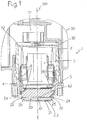
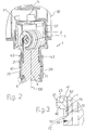
- the pressure transmitter according to the present invention is indicated as a whole with the reference numeral 1 in figures 1-2 , wherein in figure 1 the pressure transmitter is illustrated in a first embodiment as a gauge pressure transmitter while in figure 2 it is illustrated as a differential pressure transmitter.
- the pressure transmitter 1 comprises a sensor assembly having a hollow main body 2 for housing a sensor, typically a pressure sensor 3 whose structure and functioning, including circuitry, are well known to those skilled in the art and therefore will not be described herein in further details.
- the hollow main body 2 is made of any suitable material, for example metallic material such as stainless steel.
- the pressure transmitter 1 comprises a transmitter body 30 which is suitably connected to the sensor assembly, and in particular to the hollow body 2; the transmitter body 30 houses electric/electronic circuitry 31 which receives input signals from the pressure sensor 3, via connection elements 32, e.g. cables.
- the circuitry 31, which usually comprises a microprocessor, elaborates input signals received so as to output a measure of the pressure of a process fluid which is monitored by the pressure transmitter itself 1; for example, the transmitter body 30 can be made of plastic and/or metallic material.
- the pressure transmitter 1 further comprises a support body 4 which is made of a metallic material ("hereinafter first material"), for example a common stainless steel such as AISI 316 L; as schematically shown in the embodiments of figures 1 and 2 , the support body 4 is connected to the hollow body 2, e.g. by means of soldering or through screws; alternatively, it would be possible to realize the hollow body 2 and the support body 4 as a unique structurally monolithic piece.
- first material for example a common stainless steel such as AISI 316 L
- the transmitter body 30 may be realized in a single piece with the hollow body 2 and shaped so as to have inside space enough to accommodate the circuitry 31 and other components.
- the pressure transmitter 1 further comprises an interface body 20 which is connected to the support body 4 and is made of metallic material (hereinafter referred to as a "second material") which is different from the first material of the supporting body 4.
- second material metallic material
- the pressure transmitter 1 comprises at least one isolation diaphragm 21 (hereinafter referred to as the "first isolation diaphragm") which is positioned onto the interface body 20 and is advantageously made of the same material of the interface body.
- the first isolation diaphragm 21 is fixed onto the interface body 20 so as to have (with respect to the interface body 20 itself) its external surface suitable for interfacing with a process fluid the pressure of which has to be measured.
- the second material of the interface body 20 and of the first isolation diaphragm 21 is selected from the group consisting of: nickel-based alloys, duplex or super-duplex stainless steel materials; according to a particularly preferred embodiment, the interface body 20 and the isolation diaphragm 21 are made of nickel-based alloys commercially known as MONEL 400 or MONEL K500.
- the first isolation diaphragm 21 is welded, more preferably laser welded, onto the support interface body 20.
- the interface body 20 can be differently shaped according to various applications; for instance, may be ring-shaped, disc shaped, or might have a substantial fully solid body, e.g. a full cylinder body.
- the interface body 20 has a substantially full body provided at one end surface with a corrugated surface 23 on which the first isolation diaphragm 21 is fixed, i.e. laser welded, and with a cross section featuring a step 25.
- the interface body 20 is positioned at one end surface of the support body 4 and is connected to the support body 4 itself.
- the interface body 20 is welded, more preferably laser welded, onto the support body 4 along at least a first welding seam 24.
- the interface body 20 is connected to the support body 4 along a surface 22 transversal with respect to the first isolation diaphragm 21 (and parallel to a reference longitudinal axis 100); preferably, the location of the welding seam 24 on the transversal surface 22 along which the interface body 20 is connected to the support body 4 is spaced apart from the first isolation diaphragm 21.
- the second isolation diaphragm 5 is for example welded, e.g. laser welded, onto the support body 4 and is in fluid communication with the pressure sensor 3 by means of a hydraulic circuit 6 filled with a fluid, preferably an incompressible fluid, such as a silicon oil.
- the second isolation diaphragm 5 comprises for example a thin elastic membrane made of metal such as for example AISI 316L, or a suitable nickel-based alloy.
- the first isolation diaphragm 21 is in fluid communication with the pressure sensor 3 via a hydraulic circuit 60 which is equivalent to the circuit 6 and is filled with the same or a similar type of incompressible fluid;
- the hydraulic circuit 60 comprises a section 61, i.e. a through channel 61 provided on the interface body 20, and a thin gap 62 left between the interface body 20 and the support body 4.
- the first isolation diaphragm 21 is arranged - e.g. its thickness and size and any other suitable parameters - are selected so as to have along the axis 100 substantially the same linear displacement of that of the second isolation diaphragm 5 when the first and the second isolation diaphragms 21, 5 are subject to substantially the same level of pressure exerted on them by the incompressible fluid of the circuit 6 and by the process fluid, respectively.
- the interface body 20 has a disc-shaped configuration which is positioned around the support body 4 so as to embrace a portion thereof and has also a corrugated surface 23 on which the first isolation diaphragm 21 is positioned.
- two isolation diaphragms 21 which are fixed, i.e. laser welded, onto the corrugated surface 23 so as each of them has its external surface suitable for interfacing with the process fluid whose pressure has to be measured.
- both isolation diaphragms 21 are made of the same material of the interface body 20, namely, a second material selected from the group consisting of: nickel-based alloys, duplex or super-duplex stainless steel materials, preferably a nickel-based alloys commercially known as MONEL 400 or MONEL K500.
- the two isolation diaphragms 21 are fixed onto the interface body 20 opposite to each other with respect to the reference longitudinal axis 100 and extend substantially parallel to the axis 100 itself, while in the embodiment of figure 1 the isolation diaphragm 21 (and the second isolation diaphragm 5 as well) is positioned transversal with respect to the longitudinal axis 100.
- the two isolation diaphragms 21 are in fluid communication with the pressure sensor 3 via a hydraulic circuit (equivalent to that illustrated in figure 1 ) which is filled with an incompressible fluid, such as a silicon oil, and comprises (for each side) a through channel 61, a thin gap 62 and passageways 63 provided onto the support body 4.
- a hydraulic circuit equivalent to that illustrated in figure 1
- an incompressible fluid such as a silicon oil
- the interface body 20 is welded, more preferably laser welded, onto the support body 4.
- the interface body 20 is connected to the support body 4 on a surface 22 substantially parallel to the couple of first isolation diaphragms 21 along a first welding seam 24 which is spaced apart from the isolation diaphragms 21 themselves.
- the interface body 20 (seen in cross-section) comprises a first portion 30 and a second portion 40, wherein the first portion has a thickness 31 smaller than the thickness 41 of the second portion 40; the interface body 20 is welded onto the support body 4 also along a second welding seam 26 located at the first portion 30 and spaced apart from the first welding seam 24 (and the isolation diaphragms themselves).
- the first portion 30 forms a thin flexible rim which allows absorbing possible deformations and therefore reducing consequent error measurements induced by this mechanical connection.
- the same result may be achieved by suitably sizing the step 25 of the interface body 20 illustrated in figure 1 .
- the pressure transmitter 1 allows achieving the intended object offering some improvements over known solutions.
- the purposive introduction of the interface body 20 and the selection of the same material for the interface body 20 and the isolation diaphragm(s) 21 allow to realize a junction between these two elements which does not lead to a deterioration of the characteristics of the interfacing isolation diaphragm, thus preventing problems of corrosion inception typical of prior art solutions.
- the pressure transmitter 1 thus conceived may undergo numerous modifications and variants all coming within the scope of the inventive concept as specified by the appended claims.
- the interface body 20, and/or the support body 4 can have a different shape or size
- the hydraulic circuits 6, 60 can be differently shaped, et cetera, provided that such possible modifications are compatible with the functions the various elements are required to perform.
Landscapes
- Physics & Mathematics (AREA)
- General Physics & Mathematics (AREA)
- Electromagnetism (AREA)
- Measuring Fluid Pressure (AREA)
Claims (11)
- Transmetteur de pression (1) comprenant :- un ensemble capteur ayant un corps creux (2) recevant un capteur de pression (3) ;- un corps de support (4) qui est réalisé en un premier matériau ;caractérisé en ce qu'il comprend en outre :- un corps d'interface (20) qui est relié audit corps de support (4) et est réalisé en un deuxième matériau différent dudit premier matériau ; et- au moins un premier diaphragme d'isolation (21) qui est fixé sur ledit corps d'interface, ledit premier diaphragme d'isolation étant en communication fluidique avec ledit capteur de pression et approprié pour servir d'interface avec un fluide de traitement, dans lequel ledit premier diaphragme d'isolation est réalisé en ledit deuxième matériau.
- Transmetteur de pression selon la revendication 1, caractérisé en ce que ledit corps d'interface est relié audit corps de support sur une surface (22) transversale par rapport audit premier diaphragme d'isolation.
- Transmetteur de pression selon la revendication 1, caractérisé en ce que ledit corps d'interface est relié audit corps de support sur une surface (22) essentiellement parallèle audit premier diaphragme d'isolation.
- Transmetteur de pression selon une ou plusieurs des revendications précédentes, caractérisé en ce que ledit corps d'interface est soudé sur ledit corps de support le long d'au moins un premier cordon de soudure (24) prévu sur ladite surface (22) qui est espacée dudit premier diaphragme d'isolation.
- Transmetteur de pression selon une ou plusieurs des revendications précédentes, caractérisé en ce qu'il comprend un deuxième diaphragme d'isolation (5) qui est placé sur ledit corps de support (4) et est en communication fluidique avec ledit capteur de pression, ledit premier diaphragme d'isolation étant agencé de manière à avoir essentiellement le même déplacement linéaire que le deuxième diaphragme d'isolation lorsque lesdits premier et deuxième diaphragmes d'isolation sont soumis à essentiellement le même niveau de pression.
- Transmetteur de pression selon la revendication 5, caractérisé en ce que ledit deuxième diaphragme d'isolation est soudé sur ledit corps de support.
- Transmetteur de pression selon une ou plusieurs des revendications 1 à 4, caractérisé en ce qu'il comprend un deuxième diaphragme d'isolation (21) qui est fixé sur ledit corps d'interface, ledit deuxième diaphragme d'isolation étant en communication fluidique avec ledit capteur de pression et approprié pour servir d'interface avec un fluide de traitement, dans lequel ledit deuxième diaphragme d'isolation est réalisé en ledit deuxième matériau.
- Transmetteur de pression selon une ou plusieurs des revendications précédentes, caractérisé en ce que ledit corps d'interface a une surface ondulée (23) sur laquelle au moins ledit premier diaphragme d'isolation est soudé.
- Transmetteur de pression selon une ou plusieurs des revendications précédentes, caractérisé en ce que ledit corps d'interface a un corps en forme de disque entourant ledit corps de support (4) et comprenant une première partie (30) et une deuxième partie (40), où ladite première partie (30) a une épaisseur (31) inférieure à l'épaisseur (41) de ladite deuxième partie (40).
- Transmetteur de pression selon la revendication 9, caractérisé en ce que ledit corps d'interface est soudé sur ledit corps de support le long d'un deuxième cordon de soudure (26) situé au niveau de ladite première partie (30) et espacé dudit premier cordon de soudure (24).
- Transmetteur de pression selon une ou plusieurs des revendications précédentes, caractérisé en ce que ledit corps d'interface et au moins ledit premier diaphragme d'isolation sont réalisés en ledit deuxième matériau qui est choisi dans le groupe constitué : d'alliages à base de nickel, d'aciers inoxydables duplex ou super-duplex.
Applications Claiming Priority (1)
| Application Number | Priority Date | Filing Date | Title |
|---|---|---|---|
| PCT/EP2009/058292 WO2011000423A1 (fr) | 2009-07-01 | 2009-07-01 | Émetteur de pression |
Publications (2)
| Publication Number | Publication Date |
|---|---|
| EP2449355A1 EP2449355A1 (fr) | 2012-05-09 |
| EP2449355B1 true EP2449355B1 (fr) | 2018-01-24 |
Family
ID=41800574
Family Applications (1)
| Application Number | Title | Priority Date | Filing Date |
|---|---|---|---|
| EP09780076.7A Active EP2449355B1 (fr) | 2009-07-01 | 2009-07-01 | Émetteur de pression |
Country Status (4)
| Country | Link |
|---|---|
| US (1) | US8479582B2 (fr) |
| EP (1) | EP2449355B1 (fr) |
| CN (1) | CN102472677A (fr) |
| WO (1) | WO2011000423A1 (fr) |
Families Citing this family (11)
| Publication number | Priority date | Publication date | Assignee | Title |
|---|---|---|---|---|
| US8813572B2 (en) * | 2011-12-06 | 2014-08-26 | Rosemount Inc. | Ferrofluid modified fill fluid for pressure transmitters |
| US9010191B2 (en) * | 2011-12-22 | 2015-04-21 | Rosemount Inc. | Pressure sensor module for sub-sea applications |
| WO2013134232A2 (fr) | 2012-03-06 | 2013-09-12 | Rosemount, Inc. | Système de mesure de pression de joint distant pour utilisation sous-marine |
| US9442031B2 (en) | 2013-06-28 | 2016-09-13 | Rosemount Inc. | High integrity process fluid pressure probe |
| EP3598097B8 (fr) | 2013-07-19 | 2023-10-11 | Rosemount, Inc. | Émetteur de pression doté d'un ensemble d'isolation avec un bouchon d'isolateur en deux parties |
| US9459170B2 (en) | 2013-09-26 | 2016-10-04 | Rosemount Inc. | Process fluid pressure sensing assembly for pressure transmitters subjected to high working pressure |
| US9234776B2 (en) | 2013-09-26 | 2016-01-12 | Rosemount Inc. | Multivariable process fluid transmitter for high pressure applications |
| EP3134716B1 (fr) * | 2014-04-25 | 2021-06-02 | Rosemount Inc. | Module de pression résistant à la corrosion pour transmetteur de pression de fluide de traitement |
| US9513183B2 (en) * | 2014-06-30 | 2016-12-06 | Rosemount Inc. | Process isolation diaphragm assembly for metal process seal |
| US9638600B2 (en) | 2014-09-30 | 2017-05-02 | Rosemount Inc. | Electrical interconnect for pressure sensor in a process variable transmitter |
| DE102015110351A1 (de) * | 2015-06-26 | 2016-12-29 | Endress + Hauser Gmbh + Co. Kg | Druckübertragungsmodul und Druckmessaufnehmer mit einem Druckübertragungsmodul |
Family Cites Families (13)
| Publication number | Priority date | Publication date | Assignee | Title |
|---|---|---|---|---|
| CN88202728U (zh) * | 1988-04-02 | 1988-12-21 | 宝鸡市秦岭晶体管厂 | 隔离型防腐差压传感器 |
| SG41962A1 (en) * | 1993-09-24 | 1997-08-15 | Rosemount Inc | Pressure transmitter isolation diaphragm |
| JP3120640B2 (ja) * | 1993-10-08 | 2000-12-25 | 株式会社日立製作所 | 圧力伝送器 |
| US5922965A (en) * | 1998-04-28 | 1999-07-13 | Rosemount Inc. | Pressure sensor and transmitter having a weld ring with a rolling hinge point |
| US6675655B2 (en) * | 2002-03-21 | 2004-01-13 | Rosemount Inc. | Pressure transmitter with process coupling |
| US7021148B2 (en) * | 2002-04-30 | 2006-04-04 | Baxter International Inc. | Apparatus and method for sealing pressure sensor membranes |
| JP2005207875A (ja) * | 2004-01-22 | 2005-08-04 | Denso Corp | 圧力センサ |
| JP4052263B2 (ja) * | 2004-03-04 | 2008-02-27 | 株式会社デンソー | 圧力センサ |
| US7373831B2 (en) * | 2004-06-25 | 2008-05-20 | Rosemount Inc. | High temperature pressure transmitter assembly |
| US7258021B2 (en) * | 2004-06-25 | 2007-08-21 | Rosemount Inc. | Process transmitter isolation assembly |
| US7430917B2 (en) * | 2006-04-10 | 2008-10-07 | Rosemount Inc. | Process transmitter with self sealing fill fluid system |
| CN102575965B (zh) * | 2009-09-29 | 2015-02-04 | Abb技术有限公司 | 用于测量工艺流体的压力的压力变送器以及相关方法 |
| US8448519B2 (en) * | 2010-10-05 | 2013-05-28 | Rosemount Inc. | Industrial process transmitter with high static pressure isolation diaphragm coupling |
-
2009
- 2009-07-01 WO PCT/EP2009/058292 patent/WO2011000423A1/fr not_active Ceased
- 2009-07-01 CN CN2009801602316A patent/CN102472677A/zh active Pending
- 2009-07-01 EP EP09780076.7A patent/EP2449355B1/fr active Active
-
2011
- 2011-12-29 US US13/340,218 patent/US8479582B2/en active Active
Also Published As
| Publication number | Publication date |
|---|---|
| CN102472677A (zh) | 2012-05-23 |
| US8479582B2 (en) | 2013-07-09 |
| EP2449355A1 (fr) | 2012-05-09 |
| US20120125112A1 (en) | 2012-05-24 |
| WO2011000423A1 (fr) | 2011-01-06 |
Similar Documents
| Publication | Publication Date | Title |
|---|---|---|
| EP2449355B1 (fr) | Émetteur de pression | |
| AU2015229218B2 (en) | Corrosion rate measurement | |
| EP2304404B1 (fr) | Système d'isolement amélioré pour la mesure d'une pression de procédé | |
| EP3356777B1 (fr) | Transmetteur de pression ayant une protection contre une surpression | |
| KR101959150B1 (ko) | 압력 센서 및 차압 센서 및 그것들을 사용한 질량 유량 제어 장치 | |
| EP3014235B1 (fr) | Sonde de pression de haute intégrité pour fluide de procédé | |
| EP3598097B1 (fr) | Émetteur de pression doté d'un ensemble d'isolation avec un bouchon d'isolateur en deux parties | |
| US20160305839A1 (en) | Pressure Sensor | |
| JP2010523975A (ja) | 圧力送信機用の膨張チャンバ | |
| JP2017053840A (ja) | 密封した圧力センサ | |
| US11668617B2 (en) | Hydraulic diaphragm seal and pressure transducer having a hydraulic diaphragm seal | |
| JP6665744B2 (ja) | 圧力センサ | |
| JP5371527B2 (ja) | 土木用圧力変換器 | |
| US20190346071A1 (en) | A system and method for manufacturing a system | |
| RU2649042C1 (ru) | Коррозионностойкий модуль давления для измерительного преобразователя давления технологической текучей среды | |
| EP1979719B1 (fr) | Transmetteur pour commander des procedes industriels | |
| US20250052633A1 (en) | Pressure transducer and differential pressure transducer |
Legal Events
| Date | Code | Title | Description |
|---|---|---|---|
| PUAI | Public reference made under article 153(3) epc to a published international application that has entered the european phase |
Free format text: ORIGINAL CODE: 0009012 |
|
| 17P | Request for examination filed |
Effective date: 20111214 |
|
| AK | Designated contracting states |
Kind code of ref document: A1 Designated state(s): AT BE BG CH CY CZ DE DK EE ES FI FR GB GR HR HU IE IS IT LI LT LU LV MC MK MT NL NO PL PT RO SE SI SK SM TR |
|
| DAX | Request for extension of the european patent (deleted) | ||
| RAP1 | Party data changed (applicant data changed or rights of an application transferred) |
Owner name: ABB SCHWEIZ AG |
|
| GRAP | Despatch of communication of intention to grant a patent |
Free format text: ORIGINAL CODE: EPIDOSNIGR1 |
|
| INTG | Intention to grant announced |
Effective date: 20170808 |
|
| GRAS | Grant fee paid |
Free format text: ORIGINAL CODE: EPIDOSNIGR3 |
|
| GRAA | (expected) grant |
Free format text: ORIGINAL CODE: 0009210 |
|
| AK | Designated contracting states |
Kind code of ref document: B1 Designated state(s): AT BE BG CH CY CZ DE DK EE ES FI FR GB GR HR HU IE IS IT LI LT LU LV MC MK MT NL NO PL PT RO SE SI SK SM TR |
|
| REG | Reference to a national code |
Ref country code: GB Ref legal event code: FG4D |
|
| REG | Reference to a national code |
Ref country code: CH Ref legal event code: EP |
|
| REG | Reference to a national code |
Ref country code: AT Ref legal event code: REF Ref document number: 966046 Country of ref document: AT Kind code of ref document: T Effective date: 20180215 |
|
| REG | Reference to a national code |
Ref country code: IE Ref legal event code: FG4D |
|
| REG | Reference to a national code |
Ref country code: DE Ref legal event code: R096 Ref document number: 602009050563 Country of ref document: DE |
|
| REG | Reference to a national code |
Ref country code: NL Ref legal event code: MP Effective date: 20180124 |
|
| REG | Reference to a national code |
Ref country code: LT Ref legal event code: MG4D |
|
| REG | Reference to a national code |
Ref country code: AT Ref legal event code: MK05 Ref document number: 966046 Country of ref document: AT Kind code of ref document: T Effective date: 20180124 |
|
| PG25 | Lapsed in a contracting state [announced via postgrant information from national office to epo] |
Ref country code: NL Free format text: LAPSE BECAUSE OF FAILURE TO SUBMIT A TRANSLATION OF THE DESCRIPTION OR TO PAY THE FEE WITHIN THE PRESCRIBED TIME-LIMIT Effective date: 20180124 |
|
| PG25 | Lapsed in a contracting state [announced via postgrant information from national office to epo] |
Ref country code: ES Free format text: LAPSE BECAUSE OF FAILURE TO SUBMIT A TRANSLATION OF THE DESCRIPTION OR TO PAY THE FEE WITHIN THE PRESCRIBED TIME-LIMIT Effective date: 20180124 Ref country code: LT Free format text: LAPSE BECAUSE OF FAILURE TO SUBMIT A TRANSLATION OF THE DESCRIPTION OR TO PAY THE FEE WITHIN THE PRESCRIBED TIME-LIMIT Effective date: 20180124 Ref country code: HR Free format text: LAPSE BECAUSE OF FAILURE TO SUBMIT A TRANSLATION OF THE DESCRIPTION OR TO PAY THE FEE WITHIN THE PRESCRIBED TIME-LIMIT Effective date: 20180124 Ref country code: NO Free format text: LAPSE BECAUSE OF FAILURE TO SUBMIT A TRANSLATION OF THE DESCRIPTION OR TO PAY THE FEE WITHIN THE PRESCRIBED TIME-LIMIT Effective date: 20180424 Ref country code: CY Free format text: LAPSE BECAUSE OF FAILURE TO SUBMIT A TRANSLATION OF THE DESCRIPTION OR TO PAY THE FEE WITHIN THE PRESCRIBED TIME-LIMIT Effective date: 20180124 Ref country code: FI Free format text: LAPSE BECAUSE OF FAILURE TO SUBMIT A TRANSLATION OF THE DESCRIPTION OR TO PAY THE FEE WITHIN THE PRESCRIBED TIME-LIMIT Effective date: 20180124 |
|
| PG25 | Lapsed in a contracting state [announced via postgrant information from national office to epo] |
Ref country code: IS Free format text: LAPSE BECAUSE OF FAILURE TO SUBMIT A TRANSLATION OF THE DESCRIPTION OR TO PAY THE FEE WITHIN THE PRESCRIBED TIME-LIMIT Effective date: 20180524 Ref country code: PL Free format text: LAPSE BECAUSE OF FAILURE TO SUBMIT A TRANSLATION OF THE DESCRIPTION OR TO PAY THE FEE WITHIN THE PRESCRIBED TIME-LIMIT Effective date: 20180124 Ref country code: AT Free format text: LAPSE BECAUSE OF FAILURE TO SUBMIT A TRANSLATION OF THE DESCRIPTION OR TO PAY THE FEE WITHIN THE PRESCRIBED TIME-LIMIT Effective date: 20180124 Ref country code: LV Free format text: LAPSE BECAUSE OF FAILURE TO SUBMIT A TRANSLATION OF THE DESCRIPTION OR TO PAY THE FEE WITHIN THE PRESCRIBED TIME-LIMIT Effective date: 20180124 Ref country code: SE Free format text: LAPSE BECAUSE OF FAILURE TO SUBMIT A TRANSLATION OF THE DESCRIPTION OR TO PAY THE FEE WITHIN THE PRESCRIBED TIME-LIMIT Effective date: 20180124 Ref country code: GR Free format text: LAPSE BECAUSE OF FAILURE TO SUBMIT A TRANSLATION OF THE DESCRIPTION OR TO PAY THE FEE WITHIN THE PRESCRIBED TIME-LIMIT Effective date: 20180425 Ref country code: BG Free format text: LAPSE BECAUSE OF FAILURE TO SUBMIT A TRANSLATION OF THE DESCRIPTION OR TO PAY THE FEE WITHIN THE PRESCRIBED TIME-LIMIT Effective date: 20180424 |
|
| REG | Reference to a national code |
Ref country code: DE Ref legal event code: R097 Ref document number: 602009050563 Country of ref document: DE |
|
| PG25 | Lapsed in a contracting state [announced via postgrant information from national office to epo] |
Ref country code: RO Free format text: LAPSE BECAUSE OF FAILURE TO SUBMIT A TRANSLATION OF THE DESCRIPTION OR TO PAY THE FEE WITHIN THE PRESCRIBED TIME-LIMIT Effective date: 20180124 Ref country code: EE Free format text: LAPSE BECAUSE OF FAILURE TO SUBMIT A TRANSLATION OF THE DESCRIPTION OR TO PAY THE FEE WITHIN THE PRESCRIBED TIME-LIMIT Effective date: 20180124 |
|
| PG25 | Lapsed in a contracting state [announced via postgrant information from national office to epo] |
Ref country code: DK Free format text: LAPSE BECAUSE OF FAILURE TO SUBMIT A TRANSLATION OF THE DESCRIPTION OR TO PAY THE FEE WITHIN THE PRESCRIBED TIME-LIMIT Effective date: 20180124 Ref country code: SM Free format text: LAPSE BECAUSE OF FAILURE TO SUBMIT A TRANSLATION OF THE DESCRIPTION OR TO PAY THE FEE WITHIN THE PRESCRIBED TIME-LIMIT Effective date: 20180124 Ref country code: CZ Free format text: LAPSE BECAUSE OF FAILURE TO SUBMIT A TRANSLATION OF THE DESCRIPTION OR TO PAY THE FEE WITHIN THE PRESCRIBED TIME-LIMIT Effective date: 20180124 Ref country code: SK Free format text: LAPSE BECAUSE OF FAILURE TO SUBMIT A TRANSLATION OF THE DESCRIPTION OR TO PAY THE FEE WITHIN THE PRESCRIBED TIME-LIMIT Effective date: 20180124 |
|
| PLBE | No opposition filed within time limit |
Free format text: ORIGINAL CODE: 0009261 |
|
| STAA | Information on the status of an ep patent application or granted ep patent |
Free format text: STATUS: NO OPPOSITION FILED WITHIN TIME LIMIT |
|
| 26N | No opposition filed |
Effective date: 20181025 |
|
| PG25 | Lapsed in a contracting state [announced via postgrant information from national office to epo] |
Ref country code: SI Free format text: LAPSE BECAUSE OF FAILURE TO SUBMIT A TRANSLATION OF THE DESCRIPTION OR TO PAY THE FEE WITHIN THE PRESCRIBED TIME-LIMIT Effective date: 20180124 |
|
| REG | Reference to a national code |
Ref country code: CH Ref legal event code: PL |
|
| PG25 | Lapsed in a contracting state [announced via postgrant information from national office to epo] |
Ref country code: MC Free format text: LAPSE BECAUSE OF FAILURE TO SUBMIT A TRANSLATION OF THE DESCRIPTION OR TO PAY THE FEE WITHIN THE PRESCRIBED TIME-LIMIT Effective date: 20180124 Ref country code: LU Free format text: LAPSE BECAUSE OF NON-PAYMENT OF DUE FEES Effective date: 20180701 |
|
| REG | Reference to a national code |
Ref country code: BE Ref legal event code: MM Effective date: 20180731 |
|
| REG | Reference to a national code |
Ref country code: IE Ref legal event code: MM4A |
|
| PG25 | Lapsed in a contracting state [announced via postgrant information from national office to epo] |
Ref country code: CH Free format text: LAPSE BECAUSE OF NON-PAYMENT OF DUE FEES Effective date: 20180731 Ref country code: FR Free format text: LAPSE BECAUSE OF NON-PAYMENT OF DUE FEES Effective date: 20180731 Ref country code: IE Free format text: LAPSE BECAUSE OF NON-PAYMENT OF DUE FEES Effective date: 20180701 Ref country code: LI Free format text: LAPSE BECAUSE OF NON-PAYMENT OF DUE FEES Effective date: 20180731 |
|
| PG25 | Lapsed in a contracting state [announced via postgrant information from national office to epo] |
Ref country code: BE Free format text: LAPSE BECAUSE OF NON-PAYMENT OF DUE FEES Effective date: 20180731 |
|
| PG25 | Lapsed in a contracting state [announced via postgrant information from national office to epo] |
Ref country code: MT Free format text: LAPSE BECAUSE OF NON-PAYMENT OF DUE FEES Effective date: 20180701 |
|
| PG25 | Lapsed in a contracting state [announced via postgrant information from national office to epo] |
Ref country code: TR Free format text: LAPSE BECAUSE OF FAILURE TO SUBMIT A TRANSLATION OF THE DESCRIPTION OR TO PAY THE FEE WITHIN THE PRESCRIBED TIME-LIMIT Effective date: 20180124 |
|
| PG25 | Lapsed in a contracting state [announced via postgrant information from national office to epo] |
Ref country code: PT Free format text: LAPSE BECAUSE OF FAILURE TO SUBMIT A TRANSLATION OF THE DESCRIPTION OR TO PAY THE FEE WITHIN THE PRESCRIBED TIME-LIMIT Effective date: 20180124 Ref country code: HU Free format text: LAPSE BECAUSE OF FAILURE TO SUBMIT A TRANSLATION OF THE DESCRIPTION OR TO PAY THE FEE WITHIN THE PRESCRIBED TIME-LIMIT; INVALID AB INITIO Effective date: 20090701 |
|
| PG25 | Lapsed in a contracting state [announced via postgrant information from national office to epo] |
Ref country code: MK Free format text: LAPSE BECAUSE OF NON-PAYMENT OF DUE FEES Effective date: 20180124 |
|
| PGFP | Annual fee paid to national office [announced via postgrant information from national office to epo] |
Ref country code: DE Payment date: 20250722 Year of fee payment: 17 |
|
| PGFP | Annual fee paid to national office [announced via postgrant information from national office to epo] |
Ref country code: IT Payment date: 20250724 Year of fee payment: 17 |
|
| PGFP | Annual fee paid to national office [announced via postgrant information from national office to epo] |
Ref country code: GB Payment date: 20250722 Year of fee payment: 17 |