EP2449558B1 - Verfahren zur überprüfung der leistung eines kerns mittels instrumentierung des kerns - Google Patents
Verfahren zur überprüfung der leistung eines kerns mittels instrumentierung des kerns Download PDFInfo
- Publication number
- EP2449558B1 EP2449558B1 EP10794576.8A EP10794576A EP2449558B1 EP 2449558 B1 EP2449558 B1 EP 2449558B1 EP 10794576 A EP10794576 A EP 10794576A EP 2449558 B1 EP2449558 B1 EP 2449558B1
- Authority
- EP
- European Patent Office
- Prior art keywords
- core
- power
- monitored
- subcritical
- reactor
- Prior art date
- Legal status (The legal status is an assumption and is not a legal conclusion. Google has not performed a legal analysis and makes no representation as to the accuracy of the status listed.)
- Not-in-force
Links
Images
Classifications
-
- G—PHYSICS
- G21—NUCLEAR PHYSICS; NUCLEAR ENGINEERING
- G21C—NUCLEAR REACTORS
- G21C17/00—Monitoring; Testing ; Maintaining
- G21C17/08—Structural combination of reactor core or moderator structure with viewing means, e.g. with television camera, periscope, window
-
- G—PHYSICS
- G21—NUCLEAR PHYSICS; NUCLEAR ENGINEERING
- G21C—NUCLEAR REACTORS
- G21C17/00—Monitoring; Testing ; Maintaining
-
- G—PHYSICS
- G21—NUCLEAR PHYSICS; NUCLEAR ENGINEERING
- G21C—NUCLEAR REACTORS
- G21C17/00—Monitoring; Testing ; Maintaining
- G21C17/10—Structural combination of fuel element, control rod, reactor core, or moderator structure with sensitive instruments, e.g. for measuring radioactivity, strain
- G21C17/108—Measuring reactor flux
-
- G—PHYSICS
- G21—NUCLEAR PHYSICS; NUCLEAR ENGINEERING
- G21D—NUCLEAR POWER PLANT
- G21D3/00—Control of nuclear power plant
- G21D3/001—Computer implemented control
-
- Y—GENERAL TAGGING OF NEW TECHNOLOGICAL DEVELOPMENTS; GENERAL TAGGING OF CROSS-SECTIONAL TECHNOLOGIES SPANNING OVER SEVERAL SECTIONS OF THE IPC; TECHNICAL SUBJECTS COVERED BY FORMER USPC CROSS-REFERENCE ART COLLECTIONS [XRACs] AND DIGESTS
- Y02—TECHNOLOGIES OR APPLICATIONS FOR MITIGATION OR ADAPTATION AGAINST CLIMATE CHANGE
- Y02E—REDUCTION OF GREENHOUSE GAS [GHG] EMISSIONS, RELATED TO ENERGY GENERATION, TRANSMISSION OR DISTRIBUTION
- Y02E30/00—Energy generation of nuclear origin
-
- Y—GENERAL TAGGING OF NEW TECHNOLOGICAL DEVELOPMENTS; GENERAL TAGGING OF CROSS-SECTIONAL TECHNOLOGIES SPANNING OVER SEVERAL SECTIONS OF THE IPC; TECHNICAL SUBJECTS COVERED BY FORMER USPC CROSS-REFERENCE ART COLLECTIONS [XRACs] AND DIGESTS
- Y02—TECHNOLOGIES OR APPLICATIONS FOR MITIGATION OR ADAPTATION AGAINST CLIMATE CHANGE
- Y02E—REDUCTION OF GREENHOUSE GAS [GHG] EMISSIONS, RELATED TO ENERGY GENERATION, TRANSMISSION OR DISTRIBUTION
- Y02E30/00—Energy generation of nuclear origin
- Y02E30/30—Nuclear fission reactors
Definitions
- the present invention relates generally to the subcritical physics testing of a light water reactor and more particularly to the physics testing of a pressurized water reactor upon start-up.
- the primary side of nuclear reactor power generating systems which are cooled with water under pressure and are comprised of a closed circuit which is isolated and in heat exchange relationship with a secondary side for the production of useful energy.
- the primary side of the reactor vessel includes a core internal structure that supports a plurality of fuel assemblies containing fissile material, the primary circuit within heat exchange steam generators, the inner volume of a pressurizer, pumps and pipes for circulating pressurized water, and the pipes connecting each of the steam generators and pumps to the reactor vessel independently.
- Each of the parts of the primary side are comprised of a steam generator, a pump, and a system of pipes which are connected to the vessel form a loop of the primary side.
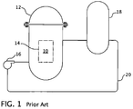
- Figure 1 shows a simplified nuclear reactor primary system, including a generally cylindrical pressure vessel 10 having a closure head 12 enclosing a nuclear core 14.
- a liquid reactor coolant such as water
- a heat exchanger 18 typically referred to as a steam generator, in which heat is transferred to a utilization circuit (not shown), such as a steam driven turbine generator.
- the reactor coolant is returned to the pump 16 completing the primary loop.
- reactor coolant piping 20 Typically, a plurality of the above-described loops are connected to a single reactor vessel 10 by reactor coolant piping 20.
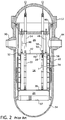
- FIG. 2 An exemplary reactor design is shown in more detail in Figure 2 .
- the other vessel internal structures can be divided into the lower internals 24 and the upper internals 26.
- the lower internals function to support, align and guide core components and instrumentation as well as direct flow within the vessel.
- the upper internals restrain or provide a secondary restraint for the fuel assemblies 22 (only two of which are shown for simplicity in this figure), and support and guide instrumentation and components, such as control rods 28.
- coolant enters the reactor vessel 10 through one or more inlet nozzles 30, flows down through an annulus between the vessel and the core barrel 32, is turned 180° in a lower plenum 34, passes upward through a lower support plate 37 and a lower core plate 36 upon which the fuel assemblies 22 are seated and through and about the assemblies.
- the fuel assemblies are restrained by the upper internals, including a circular upper core plate 40.
- Coolant exiting the core 14 flows along the underside of the upper core plate 40 and upward through a plurality of perforations 42. The coolant then flows upward and radially to one or more outlet nozzles 44.
- the upper internals 26 can be supported from the vessel or the vessel head and include an upper support assembly 46. Loads are transmitted between the upper support assembly 46 and the upper core plate 40, primarily by a plurality of support columns 48. A support column is aligned above a selected fuel assembly 22 and perforations 42 in the upper core plate 40.
- the rectilinearly movable control rods 28 typically include a drive shaft 50 and a spider assembly 52 of neutron poison rods that are guided through the upper internals 26 and into aligned fuel assemblies 22 by control rod guide tubes 54.
- the guide tubes are connected between the upper support assembly 46 and the upper core plate 40.
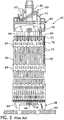
- FIG 3 is an elevational view, represented in vertically shortened form, of a fuel assembly being generally designated by reference character 22.
- the fuel assembly 22 is the type used in a pressured water reactor and has a structural skeleton which, at its lower end, includes a bottom nozzle 58.
- the bottom nozzle 58 supports the fuel assembly 22 on a lower core support plate 60 in the core region of a nuclear reactor (the lower core support plate 60 shown in Figure 3 is represented by reference character 36 in Figure 2 ).
- the structural skeleton of the fuel assembly 22 also includes a top nozzle 62 at its upper end and a number of guide tubes or thimbles 84, which extend longitudinally between the bottom and top nozzles 58 and 62 and at opposite ends are rigidly attached thereto.
- the fuel assembly 22 further includes a plurality of transverse grids 64 axially spaced along and mounted to the guide thimbles 84 (also referred to as guide tubes) and an organized array of elongated fuel rods 66 transversely spaced and supported by the grids 64.
- the grids 64 are conventionally formed from orthogonal straps that are interleaved in an egg-crate pattern with the adjacent interface of four straps defining approximately square support cells through which the fuel rods 66 are supported in transversely spaced relationship with each other.
- springs and dimples are stamped into the opposing walls of the straps that form the support cells.
- the springs and dimples extend radially into the support cells and capture the fuel rods there between; exerting pressure on the fuel rod cladding to hold the rods in position.
- the assembly 22 has an instrumentation tube 68 located in the center thereof that extends between and is either mounted to or passes through the bottom and top nozzles 58 and 62. The former is illustrated in Figure 3 .
- Each fuel rod 66 includes a plurality of nuclear fuel pellets 70 and is closed at its opposite ends by upper and lower end plugs 72 and 74.
- the pellets 70 are maintained in a stack by a plenum spring 76 disposed between the upper end plug 72 and the top of the pellet stack.
- the fuel pellets 70 composed of fissile material, are responsible for creating the reactive power of the reactor.
- the cladding which surrounds the pellets functions as a barrier to prevent the fission by-products from entering the coolant and further contaminating the reactor system.
- a number of control rods 78 are reciprocably movable in the guide thimbles 84 located at predetermined positions in the fuel assembly 22.
- a rod cluster control mechanism 80 positioned above the top nozzle 62 supports the control rods 78.
- the control mechanism has an internally threaded hub member 82 with a plurality of radially extending flukes or arms 52. Each arm 52 is interconnected to the control rods 78 such that the control mechanism 80 is operable to move the control rods vertically in the guide thimbles 84 to thereby control the fission process in the fuel assembly 22, under the motor power of control rod drive shafts 50 which are coupled to the control rod hubs 82, all in a well-known manner.
- heat is generated within the core of the pressure vessel by a fission chain reaction occurring in the plurality of fuel rods supported within the core.
- the fuel rods are maintained in spaced relationship within the fuel assemblies and the space between the fuel rods forms coolant channels through which borated water flows.
- Hydrogen within the coolant water moderates the neutrons emitted from enriched uranium within the fuel to increase the number of nuclear reactions and thus increase the efficiency of the process.
- the control rod guide thimbles that are interspersed within the fuel assemblies in place of fuel rod locations serve to guide the control rods which are operable to be inserted or withdrawn from the core. When inserted, the control rods absorb neutrons and thus reduce the number of nuclear reactions and the amount of heat generated within the core.
- the power level of a nuclear reactor is generally divided into three ranges: the source or start-up range, the intermediate range, and the power range.
- the power level of the reactor is continuously monitored to assure safe operation. Such monitoring is typically conducted by means of neutron detectors placed outside and inside the reactor core for measuring the neutron flux of the reactor. Since the neutron flux in the reactor at any point is proportional to the fission rate, the neutron flux is also proportional to the power level.
- Fission and ion chambers have been used to measure flux in the source, intermediate and power range of a reactor. Typically fission and ionization chambers are capable of operating at all normal power levels, however, they are generally not sensitive enough to accurately detect low level neutron flux emitted in the source range. Thus, separate low level source range protectors are typically used to monitor neutron flux when the power level of the reactor is in the source range.
- the fission reactions within the core occur when free neutrons at the proper energy levels strike the atoms of the fissionable material contained within the fuel rods.
- the reactions result in the release of a large amount of heat energy which is extracted from the core in the reactor coolant and in the release of additional free neutrons which are available to produce more fission reactions.
- Some of these released neutrons escape the core or are absorbed by neutron absorbers, e.g., control rods, and therefore do not cause traditional fission reactions.
- the rate of fission can be controlled.
- the process becomes a self-sustaining chain reaction and the reactor is said to be "critical".
- the neutron flux is six or so orders of magnitude higher than when the reactor is shut down.
- an artificial neutron source is implanted in the reactor core among the fuel rods containing the fissionable material. This artificial neutron source creates a localized increase in the neutron flux to aid in bringing the reactor up to power.
- K eff the ratio of the number of free neutrons in one generation to those in the previous generation
- K eff the measure of the reactivity of the reactor.
- K eff the measure of criticality for a nuclear core
- K eff the measure of criticality for a nuclear core
- the foundation on which physics testing stands is observing an expected response from the core.
- Several current physics testing programs such as the Dynamic Rod Worth Measurement program or the Subcritical Rod Worth Measurement program are capable of accurately confirming all of the previously listed parameters.
- the Dynamic Rod Worth Measurement program uses one of a nuclear plant's four excore power range detectors (which is required to be taken out of service) to perform the testing while the reactor is in the zero power test range. To perform the measurement, groups of control rods are individually inserted and removed from the core in a continuous motion at the maximum rod stepping speed. After each group is removed from the core, it is necessary to allow the flux to recover to the initial starting level.
- the Subcritical Rod Worth Measurement program uses both of a nuclear plant's source range detectors, without requiring them to be taken out of service. Testing is performed while the reactor is subcritical (K eff ⁇ 0.99) and requires less complicated control rod maneuvers than the Dynamic Rod Worth Measurement program, which makes the testing easier and more familiar to the reactor operator.
- the control rods are withdrawn in the manner typical in preparing for Hot Rod Drop timing measurement testing.
- the Subcritical Rod Worth Measurement program specifies state points at which the source range detector count rate data is collected. Rod withdrawal is briefly stopped at each state point to collect the necessary data and the process continues until reaching an all rods out condition.
- the Subcritical Rod Worth Measurement program then calculates the total control rod worth and the critical boron concentration from the source range data collected at each state point.
- an isothermal temperature coefficient measurement is performed by changing system temperature by approximately 6°F (3.3°C) and determining the corresponding change in reactivity. This determination is made using the relationship between the change in reactivity and the change in ex-core detector indication measured during the rod withdrawals.
- the subcritical Rod Worth Measurement verification method uses the SubCritical Inverse Count Rate methodology that is more fully described in U.S. Patent Application Serial No. 12/332,577, filed December 11, 2008 , to predict the subcritical core neutron distribution which enables the linearization of the highly non-linear Inverse Count Rate Ratio so that K eff changes can be determined from spatially corrected source range detector signal measurements.
- the voltage from the source range detectors that was monitored at each state point is converted to counts and K eff at each state point.
- the total change in reactivity during the rod pulls determines the total bank worth.
- the Spatially Corrected Inverse Count Rate Ratio is then extrapolated to zero to determine the necessary reactivity to go critical (or the boron end point).
- This extrapolated point provides an accurate measurement of an expected critical condition which enables the plant to pull rods to take the plant critical, rather than having to dilute the boron concentration in the coolant to reach critically without a known expected critical condition based on that particular fuel cycle's core experience.
- the agreement between the actual and predicted core power distribution relies on the measurement of the mean Inverse Count Rate Ratio deviations from the predicted value (MD) divided by the measured Root Mean Square differences of the measured Inverse Count Rate Ratio from the predicted values (RMS) over the withdrawal of all of the control and shut-down banks, or MD/RMS. While this method has proven accurate during its many applications, a flux map at 30% rated thermal power is still required to further verify core power distribution.
- a new subcritical physics testing program is desired that will save outage critical path time. Furthermore, an improved subcritical physics testing program is desired that will completely remove the required subcritical physics testing form the outage critical path. Additionally, an improved physics testing program is desired that will confirm that the core will operate as designed above criticality.
- This invention achieves the foregoing objectives by providing a subcritical physics testing method, as defined in claim 1, that employs measurements taken from incore instrumentation housed within instrument thimbles within the fuel assemblies of the core.
- the incore instrumentation positioned at a number of radial locations within the core monitors the neutron flux in the core over a plurality of axial zones, substantially along an active length of the fissile fuel elements.
- the method first analytically predicts a power distribution for the core.
- the method withdraws the control rods from the core in a pre-established sequence to raise the power level of the core within a subcritical power range. While the control rods are being withdrawn, the method monitors the power level at the axial and radial core locations monitored by the incore instrumentation to obtain a monitored power distribution from one or more outputs of the incore instrumentation. The method then compares the analytically predicted power distribution to the monitored power distribution. If the monitored and predicted power distributions are within a preselected deviation, the method continues normal reactor startup to bring the reactor up to power without interruption, so long as the monitored power remains within specifications.
- the monitoring step provides an integrated fuel assembly neutron flux distribution measurement at various reactor temperatures and control rod position configurations as the control rods are withdrawn.
- the integrated fuel assembly neutron flux distribution measurement is obtained by integrating the output of the incore instrumentation until a fractional uncertainty in the relative output meets a specified uncertainty level. The method then compares the monitored power distribution against a corresponding predicted signal distribution that was part of the analytically predicted power distribution to identify if there are any significant deviations between the monitored and predicted power distributions.
- the method preferably includes the step of using the monitored axial and radial power levels obtained at different temperatures and rod positions to quantify reactivity changes that occur between the different temperatures and rod positions so that a temperature coefficient of reactivity and a reactivity worth of the control rods can be determined and compared to predicted values.
- the method includes the step of continuing to compare the analytically predicted power distribution to the monitored power distribution as the reactor goes critical up until a predetermined power range.
- the incore instrument subcritical verification program of this invention in many respects is similar to the Subcritical Rod Worth Measurement program. The main difference is that this invention employs Optimized Proportional Axial Region Signal Separation Extended Life (OPARSSELTM) incore instrumentation thimble assemblies that are more fully described in U.S. Patent 5,745,538 .
- OPARSSELTM Proportional Axial Region Signal Separation Extended Life
- vanadium fixed incore detectors instead of the excore source range detectors enable the subcritical and low power physics testing to be carried out and completed during and without interruption of the start-up procedure, which removes the core design verification activities from the outage critical path.
- the OPARSSEL incore instrumentation thimble assemblies replace the movable incore detector systems employed in many pressurized water reactors.
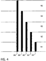
- FIG 4 represents a schematic of the detector element configuration inside the incore flux detector instrumentation thimble assemblies.
- a vanadium incore detector element in a neutron flux produces a signal caused by the absorption of a neutron by the vanadium-51 isotope to produce vanadium-52.
- the vanadium-52 isotope decays by beta emission, which produces an electrical current proportional to the neutron flux.
- Each incore instrumentation thimble assembly houses multiple variable length self-powered detector elements to provide an axial core power distribution. Typically five detector elements are provided as illustrated in Figure 4 , but newer reactors, such as AP1000, employ as many as seven detector elements.
- the longest detector emitter 86 spans the entire active fuel element length, extending over regions R1-R5 and provides an integrated measurement of the total neutron flux contained within the associated fuel assembly.
- the shorter detector elements 88, 90, 92 and 94 provide signals that can be used to determine the relative fraction of the total neutron flux being generated at the different axial regions R1-R5 of the fuel assembly defined by the overlap with the longest detector element 86.
- This information allows measurement of the relative radial and axial power shape in all of the core locations containing incore instrumentation thimble assemblies. This measured information can then be compared to the corresponding predicted relative axial and radial power distribution information to identify whether there are any significant differences from the expected conditions.
- the total signal measured from all of the detector elements can also be used to establish whether there is a global reactivity bias between the as built and predicted core.
- the incore instrumentation subcritical verification program of this invention thus uses the self-powered detectors in the incore instrumentation thimble assemblies to provide an integrated fuel assembly neutron flux distribution measurement at various temperatures and rod position configurations similar to the manner in which the Subcritical Rod Worth Measurement program processes the source range detector signals.
- the measurement information is obtained by integrating the current signal's output from each detector emitter until the fractional uncertainty in the relative detector signals meets a specified uncertainty level. The measured detector signal distribution is then compared against a corresponding predicted signal distribution to identify if there are any significant deviations between the measured and predicted radial and axial power distribution.
- control rod withdrawal is carried out in a pre-established sequence and desirably is continuous without the need for state points for the collection of data.
- An additional advantage of the incore instrument subcritical verification program of this invention is that the comparison between actual and predicted power distributions and other core parameters can continue at power levels above the point where the reactor goes critical to further validate the safety analyses that were performed for the core.
- the use of the core design verification methodology of this invention significantly enhances the accuracy, safety and convenience of the core design verification process and essentially removes all core design verification activities from the outage critical path.
Landscapes
- Engineering & Computer Science (AREA)
- Physics & Mathematics (AREA)
- General Engineering & Computer Science (AREA)
- Plasma & Fusion (AREA)
- High Energy & Nuclear Physics (AREA)
- Monitoring And Testing Of Nuclear Reactors (AREA)
Claims (7)
- Unterkritisches physikalisches Prüfverfahren zur Bestätigung, dass ein Kern (14) eines Kernreaktors konstruktionsgemäß arbeitet, wobei der Kern (14) eine radiale und axiale Dimension sowie eine Vielzahl von Brennstoffanordnungen (22) mit einer Reihe von spaltbaren Brennstoffelementen aufweist, wobei zumindest einige der Brennstoffanordnungen (22) Führungs-Fingerhutrohre (84) zum Einführen von Steuerstäben (28) aufweisen, die in Gruppen in und aus dem Kern beweglich sind, und zumindest einem Instrumentierungs-Fingerhutrohr (68), in dem eine Innenkern-Instrumentierung untergebracht ist, um den Neutronenfluss in dem Kern (14) an einer radialen Position um die Innenkern-Instrumentierung und über eine Vielzahl von axialen Zonen im Wesentlichen entlang einer aktiven Länge der spaltbaren Brennstoffelemente (66) zu überwachen, wobei das Verfahren folgende Schritte umfasst:analytisches Prognostizieren einer Leistungsverteilung in dem Kern (14);anfängliches Halten des Kerns (14) in einem unterkritischen Abschaltzustand mit Keff unter eins, durch die Einführung zumindest einiger der Steuerstäbe (28) in den Kern (14) und/oder durch Zugabe eines chemischen Neutronenabsorbers in den Kern (14);Ausfahren der Steuerstäbe (28) aus dem Kern (14) in einer zuvor festgelegten Abfolge, um das Leistungsniveau (14) des Kerns innerhalb eines unterkritischen Leistungsbereichs anzuheben, wobei der Schritt des Ausfahrens die Steuerstäbe (28) kontinuierlich aus dem Kern (14) ausfährt;Überwachen eines Leistungsniveaus an den axialen und radialen Kernpositionen, die durch die Innenkern-Instrumentierung unter Verwendung von festen Vanadium-Innenkern-Detektoren (86, 88, 90,92, 94) überwacht werden, um eine überwachte Leistungsverteilung von einem oder mehreren Ausgängen der Innenkern-Instrumentierung zu erhalten, während das Leistungsniveau innerhalb des unterkritischen Leistungsbereichs angehoben wird; undVergleichen der analytisch prognostizierten Leistungsverteilung mit der überwachten Leistungsverteilung und, wenn die überwachte und die prognostizierte Leistungsverteilung innerhalb einer vorgewählten Abweichung liegen, Fortsetzen des normalen Reaktorhochfahrvorgangs, um den Reaktor ohne Unterbrechung auf Leistung zu bringen, so lange die überwachte Leistung innerhalb der Vorgaben bleibt.
- Unterkritisches physikalisches Prüfverfahren nach Anspruch 1, wobei der Überwachungsschritt eine integrierte Brennstoffanordnungs-Neutronenflussverteilungsmessung bei verschiedenen Reaktortemperaturen und Steuerstabstellungskonfigurationen bereitstellt, während die Steuerstäbe (28) ausgefahren werden.
- Unterkritisches physikalisches Prüfverfahren nach Anspruch 2, wobei die integrierte Brennstoffanordnungs-Neutronenflussverteilungsmessung erhalten wird, indem der Ausgang der Innenkern-Instrumentierung integriert wird, bis eine Unsicherheit in dem relativen Ausgang ein angegebenes Unsicherheitsniveau erfüllt, und dann die überwachte Leistungsverteilung mit einer entsprechenden vorhergesagten Signalverteilung verglichen wird, die Teil der analytisch prognostizierten Leistungsverteilung war, um zu identifizieren, ob beträchtliche Abweichungen zwischen den überwachten und vorhergesagten Leistungsverteilungen bestehen.
- Unterkritisches physikalisches Prüfverfahren nach Anspruch 3, umfassend den Schritt der Verwendung der überwachten axialen und radialen Leistungsniveaus, die bei unterschiedlichen Temperaturen und Stabstellungen erhalten wurden, um Reaktivitätsveränderungen zu quantifizieren, die zwischen den unterschiedlichen Temperaturen und Stabstellungen auftreten, so dass ein Reaktivitäts-Temperaturkoeffizient bestimmt und mit prognostizierten Werten verglichen werden kann.
- Unterkritisches physikalisches Prüfverfahren nach Anspruch 3, umfassend den Schritt der Verwendung der überwachten axialen und radialen Leistungsniveaus, die bei unterschiedlichen Temperaturen und Stabstellungen erhalten wurden, um Reaktivitätsveränderungen zu quantifizieren, die zwischen den unterschiedlichen Temperaturen und Stabstellungen auftreten, so dass ein Reaktivitätswert der Steuerstäbe (28) bestimmt und mit prognostizierten Werten verglichen werden kann.
- Unterkritisches physikalisches Prüfverfahren nach Anspruch 3, umfassend den Schritt der Verwendung der überwachten axialen und radialen Leistungsniveaus, die bei unterschiedlichen Temperaturen und Stabstellungen erhalten wurden, um Reaktivitätsveränderungen zu quantifizieren, die zwischen den unterschiedlichen Temperaturen und Stabstellungen auftreten, so dass eine kritische Borkonzentration bei vollständig ausgefahrenen Steuerstäben bestimmt und mit prognostizierten Werten verglichen werden kann.
- Physikalisches Prüfverfahren nach Anspruch 1, wobei innerhalb des unterkritischen Leistungsbereichs die überwachte und die prognostizierte Leistungsverteilung innerhalb der vorgewählten Abweichung liegen, umfassend den Schritt des kontinuierlichen Vergleichens der analytisch prognostizierten Leistungsverteilung mit der überwachten Leistungsverteilung, während der Reaktor kritisch bis zu einem vorbestimmten Leistungsbereich hochfährt.
Priority Applications (1)
| Application Number | Priority Date | Filing Date | Title |
|---|---|---|---|
| SI201031207A SI2449558T1 (sl) | 2009-07-01 | 2010-06-25 | Metoda za preverjanje delovanja sredice z instrumentacijo reaktorske sredice |
Applications Claiming Priority (2)
| Application Number | Priority Date | Filing Date | Title |
|---|---|---|---|
| US12/495,981 US20110002432A1 (en) | 2009-07-01 | 2009-07-01 | Incore instrument core performance verification method |
| PCT/US2010/039904 WO2011002670A1 (en) | 2009-07-01 | 2010-06-25 | Incore instrument core performance verification method |
Publications (3)
| Publication Number | Publication Date |
|---|---|
| EP2449558A1 EP2449558A1 (de) | 2012-05-09 |
| EP2449558A4 EP2449558A4 (de) | 2014-02-19 |
| EP2449558B1 true EP2449558B1 (de) | 2016-04-27 |
Family
ID=43411385
Family Applications (1)
| Application Number | Title | Priority Date | Filing Date |
|---|---|---|---|
| EP10794576.8A Not-in-force EP2449558B1 (de) | 2009-07-01 | 2010-06-25 | Verfahren zur überprüfung der leistung eines kerns mittels instrumentierung des kerns |
Country Status (10)
| Country | Link |
|---|---|
| US (1) | US20110002432A1 (de) |
| EP (1) | EP2449558B1 (de) |
| JP (1) | JP5496328B2 (de) |
| KR (1) | KR101629535B1 (de) |
| CN (1) | CN102473466B (de) |
| ES (1) | ES2579080T3 (de) |
| RU (1) | RU2508571C2 (de) |
| SI (1) | SI2449558T1 (de) |
| TW (1) | TWI505289B (de) |
| WO (1) | WO2011002670A1 (de) |
Cited By (1)
| Publication number | Priority date | Publication date | Assignee | Title |
|---|---|---|---|---|
| TWI773001B (zh) * | 2019-12-06 | 2022-08-01 | 美商西屋電器公司 | 使用釩中子探測器的方法和用具 |
Families Citing this family (27)
| Publication number | Priority date | Publication date | Assignee | Title |
|---|---|---|---|---|
| GB201200878D0 (en) | 2012-01-19 | 2012-02-29 | British American Tobacco Co | Polymer compositions |
| US20110268239A1 (en) * | 2010-04-30 | 2011-11-03 | David Jerome Krieg | Method of calibrating excore detectors in a nuclear reactor |
| US8681920B2 (en) * | 2011-01-07 | 2014-03-25 | Westinghouse Electric Company Llc | Self-powered wireless in-core detector |
| US8767903B2 (en) | 2011-01-07 | 2014-07-01 | Westinghouse Electric Company Llc | Wireless in-core neutron monitor |
| CN102411997B (zh) * | 2011-10-25 | 2014-04-02 | 清华大学 | 高温气冷堆功率控制方法及系统 |
| US9182290B2 (en) * | 2011-12-30 | 2015-11-10 | Ge-Hitachi Nuclear Energy Americas Llc | Methods and apparatuses for monitoring nuclear reactor core conditions |
| US8958519B2 (en) * | 2012-04-17 | 2015-02-17 | Babcock & Wilcox Mpower, Inc. | Incore instrumentation cable routing and support element for pressurized water reactor |
| US9208907B2 (en) * | 2012-11-13 | 2015-12-08 | Westinghouse Electric Company Llc | Method of validating nuclear reactor in-vessel detector output signals |
| CN103345950B (zh) * | 2013-07-12 | 2017-02-08 | 中广核研究院有限公司 | 压水堆堆外核探测系统及探测方法 |
| RU2546662C1 (ru) * | 2013-10-31 | 2015-04-10 | Открытое Акционерное Общество "Акмэ-Инжиниринг" | Способ обеспечения гарантированной подкритичности активной зоны быстрого реактора в условиях неопределенности ее нейтронно-физических характеристик |
| US9761332B2 (en) * | 2014-06-09 | 2017-09-12 | Bwxt Mpower, Inc. | Nuclear reactor neutron shielding |
| EP3170185B1 (de) | 2014-07-14 | 2019-02-27 | Westinghouse Electric Company Llc | Thermoakustische messanordnung für atomkraftverteilung |
| US9478320B2 (en) * | 2014-08-18 | 2016-10-25 | Westinghouse Electric Company Llc | Method for in-core instrumentation withdrawal from the core of a pressurized water reactor |
| US20170140842A1 (en) * | 2015-11-12 | 2017-05-18 | Westinghouse Electric Company Llc | Subcritical Reactivity Monitor Utilizing Prompt Self-Powered Incore Detectors |
| CN105448361B (zh) * | 2015-11-12 | 2017-11-21 | 中广核工程有限公司 | 一种核电站堆芯状态的监测方法、服务器及系统 |
| ES3015739T3 (en) * | 2017-12-12 | 2025-05-07 | Westinghouse Electric Co Llc | Subcritical core reactivity bias projection technique |
| CN108416135B (zh) * | 2018-03-02 | 2021-07-30 | 中国核电工程有限公司 | 一种由测量单组棒价值拟合应急保护价值的方法及装置 |
| CN109273119B (zh) * | 2018-09-13 | 2022-02-11 | 中国核动力研究设计院 | 在临界装置上测量大反应性时优化中子探测器位置的方法 |
| CN109887627B (zh) * | 2019-02-26 | 2020-07-03 | 三门核电有限公司 | 一种堆芯平均轴向通量偏差获取系统 |
| CN111933320A (zh) * | 2020-08-12 | 2020-11-13 | 上海核工程研究设计院有限公司 | 一种利用标准探测器进行中子探测器堆上试验验证的方法 |
| CN112397211B (zh) * | 2020-11-18 | 2022-08-30 | 山东核电有限公司 | 一种任意控制棒位置下压水堆燃料相关组件配插分析方法 |
| CN112418507B (zh) * | 2020-11-19 | 2023-01-13 | 山东核电有限公司 | 一种固定控制棒位置下压水堆燃料相关组件配插分析方法 |
| CN112712909B (zh) * | 2020-11-20 | 2024-01-23 | 中国核电工程有限公司 | 可溶中子毒物的加料装置 |
| CN112885492B (zh) * | 2021-01-12 | 2023-03-07 | 中国原子能科学研究院 | 零功率反应堆实验模拟装置及其进行临界实验的模拟方法 |
| US11977193B2 (en) * | 2022-07-18 | 2024-05-07 | Westinghouse Electric Company Llc | Wireless power level and power distribution monitoring and control system for subcritical spent fuel assembly array using removable SIC neutron detector thimble tube |
| CN116682585B (zh) * | 2023-06-19 | 2025-11-28 | 中广核研究院有限公司 | 堆芯功率分布测量不确定性的分析方法、装置和设备 |
| CN118507090B (zh) * | 2024-05-29 | 2025-09-19 | 中核核电运行管理有限公司 | 一种重水堆次临界下调节棒价值测量方法 |
Family Cites Families (24)
| Publication number | Priority date | Publication date | Assignee | Title |
|---|---|---|---|---|
| US3932211A (en) * | 1973-07-13 | 1976-01-13 | Westinghouse Electric Corporation | Method of automatically monitoring the power distribution of a nuclear reactor employing movable incore detectors |
| JPS5135890A (en) * | 1974-09-20 | 1976-03-26 | Hitachi Ltd | Genshiro no jidokidoseigyosochi |
| JPS5637592A (en) * | 1979-09-05 | 1981-04-11 | Hitachi Ltd | Nuclear reactor power distribution forcasting device |
| JPS56140294A (en) * | 1980-04-04 | 1981-11-02 | Hitachi Ltd | Nuclear reactor power adistribution device |
| USH63H (en) * | 1983-07-07 | 1986-05-06 | The United States Of America As Represented By The United States Department Of Energy | Positioning apparatus |
| JP2509901B2 (ja) * | 1984-10-25 | 1996-06-26 | 株式会社日立製作所 | 原子炉出力分布監視方法 |
| US4877575A (en) * | 1988-01-19 | 1989-10-31 | Westinghouse Electric Corp. | Core reactivity validation computer and method |
| JPH02157695A (ja) * | 1988-12-12 | 1990-06-18 | Mitsubishi Atom Power Ind Inc | 加圧水型原子炉の反応度係数測定方法 |
| US5024801A (en) * | 1989-05-01 | 1991-06-18 | Westinghouse Electric Corp. | Reactor core model update system |
| US5229066A (en) | 1991-08-05 | 1993-07-20 | Westinghouse Electric Corp. | Control rod position indication system |
| US5215707A (en) * | 1991-09-10 | 1993-06-01 | Siemens Power Corporation | Instrument thimble tube shroud |
| US5251242A (en) * | 1992-06-22 | 1993-10-05 | Westinghouse Electric Corp. | Bi-metallic, self powered, fixed incore detector, and method of calibrating same |
| JPH0980188A (ja) * | 1995-09-18 | 1997-03-28 | Mitsubishi Heavy Ind Ltd | 加圧水型原子炉及びその非核燃料炉心構成体 |
| US6061412A (en) * | 1995-10-05 | 2000-05-09 | Westinghouse Electric Company Llc | Nuclear reaction protection system |
| US5745538A (en) * | 1995-10-05 | 1998-04-28 | Westinghouse Electric Corporation | Self-powered fixed incore detector |
| ES2190212T3 (es) * | 1998-04-28 | 2003-07-16 | Framatome Anp Gmbh | Procedimiento y dispositivo para el control de la subida de potencia durante la puesta en marcha de un reactor nuclear (control de excursion diversitaria). |
| US6310929B1 (en) * | 1998-08-25 | 2001-10-30 | Kabushiki Kaisha Toshiba | In-core fixed nuclear instrumentation system and power distribution monitoring system |
| US6181759B1 (en) * | 1999-07-23 | 2001-01-30 | Westinghouse Electric Company Llc | Method and apparatus for determining nearness to criticality of a nuclear fueled electric power generating unit |
| US6748348B1 (en) * | 1999-12-30 | 2004-06-08 | General Electric Company | Design method for nuclear reactor fuel management |
| TW594791B (en) | 2001-09-27 | 2004-06-21 | Toshiba Corp | Incore monitoring method and incore monitoring equipment |
| US6801593B2 (en) * | 2002-11-21 | 2004-10-05 | Westinghouse Electric Company Llc | Subcritical reactivity measurement method |
| US7200541B2 (en) * | 2002-12-23 | 2007-04-03 | Global Nuclear Fuel-Americas, Llc | Method and arrangement for determining nuclear reactor core designs |
| US7574337B2 (en) * | 2004-12-30 | 2009-08-11 | Global Nuclear Fuel - Americas, Llc | Method of determining a fresh fuel bundle design for a core of a nuclear reactor |
| JP4773937B2 (ja) * | 2006-02-09 | 2011-09-14 | ウエスチングハウス・エレクトリック・カンパニー・エルエルシー | 原子炉保護システム及び原子炉を監視する方法 |
-
2009
- 2009-07-01 US US12/495,981 patent/US20110002432A1/en not_active Abandoned
-
2010
- 2010-06-25 ES ES10794576.8T patent/ES2579080T3/es active Active
- 2010-06-25 SI SI201031207A patent/SI2449558T1/sl unknown
- 2010-06-25 WO PCT/US2010/039904 patent/WO2011002670A1/en not_active Ceased
- 2010-06-25 CN CN201080028676.1A patent/CN102473466B/zh active Active
- 2010-06-25 KR KR1020117031684A patent/KR101629535B1/ko active Active
- 2010-06-25 JP JP2012517756A patent/JP5496328B2/ja active Active
- 2010-06-25 EP EP10794576.8A patent/EP2449558B1/de not_active Not-in-force
- 2010-06-25 RU RU2012103325/07A patent/RU2508571C2/ru active
- 2010-07-01 TW TW099121712A patent/TWI505289B/zh active
Non-Patent Citations (1)
| Title |
|---|
| None * |
Cited By (2)
| Publication number | Priority date | Publication date | Assignee | Title |
|---|---|---|---|---|
| TWI773001B (zh) * | 2019-12-06 | 2022-08-01 | 美商西屋電器公司 | 使用釩中子探測器的方法和用具 |
| EP4070340A1 (de) * | 2019-12-06 | 2022-10-12 | Westinghouse Electric Company Llc | Verfahren und vorrichtung unter verwendung von vanadiumneutronendetektoren |
Also Published As
| Publication number | Publication date |
|---|---|
| KR101629535B1 (ko) | 2016-06-10 |
| EP2449558A4 (de) | 2014-02-19 |
| KR20120031482A (ko) | 2012-04-03 |
| SI2449558T1 (sl) | 2016-09-30 |
| TWI505289B (zh) | 2015-10-21 |
| RU2012103325A (ru) | 2013-08-20 |
| EP2449558A1 (de) | 2012-05-09 |
| CN102473466B (zh) | 2015-01-21 |
| JP5496328B2 (ja) | 2014-05-21 |
| TW201108247A (en) | 2011-03-01 |
| US20110002432A1 (en) | 2011-01-06 |
| WO2011002670A1 (en) | 2011-01-06 |
| JP2012532315A (ja) | 2012-12-13 |
| ES2579080T3 (es) | 2016-08-04 |
| RU2508571C2 (ru) | 2014-02-27 |
| CN102473466A (zh) | 2012-05-23 |
Similar Documents
| Publication | Publication Date | Title |
|---|---|---|
| US20110002432A1 (en) | Incore instrument core performance verification method | |
| US11430578B2 (en) | Subcritical reactivity monitor utilizing prompt self-powered in-core detectors | |
| CN105723467B (zh) | 一种用于在反应堆停机期间监控硼稀释的方法 | |
| US9287014B2 (en) | Thermo-acoustic nuclear power distribution measurement assembly | |
| US20110264426A1 (en) | Methodology for modeling the fuel rod power distribution within a nuclear reactor core | |
| EP2920789B1 (de) | Verfahren zur überprüfung von gefässinternen kernreaktor-detektor-ausgangssignalen | |
| WO2009134498A2 (en) | A methodology for modeling the fuel rod power distribution within a nuclear reactor core | |
| US20140321591A1 (en) | Thermo-acoustic nuclear power distribution measurement assembly | |
| Gourdon et al. | An overview of Superphenix commissioning tests | |
| Crawford et al. | RIA testing capability of the transient reactor test facility | |
| Bays et al. | Startup Physics Testing of Advanced Reactors | |
| Bozzola | Fundamentals of boiling water reactor (bwr) | |
| Oka et al. | Safety |
Legal Events
| Date | Code | Title | Description |
|---|---|---|---|
| PUAI | Public reference made under article 153(3) epc to a published international application that has entered the european phase |
Free format text: ORIGINAL CODE: 0009012 |
|
| 17P | Request for examination filed |
Effective date: 20111128 |
|
| AK | Designated contracting states |
Kind code of ref document: A1 Designated state(s): AL AT BE BG CH CY CZ DE DK EE ES FI FR GB GR HR HU IE IS IT LI LT LU LV MC MK MT NL NO PL PT RO SE SI SK SM TR |
|
| RIN1 | Information on inventor provided before grant (corrected) |
Inventor name: PRIBLE, MICHAEL, C. Inventor name: KISTLER, DANIEL, P. Inventor name: SEBASTIANI, PATRICK, J. Inventor name: HEIBEL, MICHAEL, D. Inventor name: CONNER, SHANNON, L. |
|
| RIN1 | Information on inventor provided before grant (corrected) |
Inventor name: SEBASTIANI, PATRICK, J. Inventor name: KISTLER, DANIEL, P. Inventor name: PRIBLE, MICHAEL, C. Inventor name: HEIBEL, MICHAEL, D. Inventor name: CONNER, SHANNON, L. |
|
| DAX | Request for extension of the european patent (deleted) | ||
| A4 | Supplementary search report drawn up and despatched |
Effective date: 20140116 |
|
| RIC1 | Information provided on ipc code assigned before grant |
Ipc: G21D 3/00 20060101ALI20140110BHEP Ipc: G21C 17/108 20060101ALI20140110BHEP Ipc: G21C 17/00 20060101AFI20140110BHEP |
|
| GRAP | Despatch of communication of intention to grant a patent |
Free format text: ORIGINAL CODE: EPIDOSNIGR1 |
|
| GRAS | Grant fee paid |
Free format text: ORIGINAL CODE: EPIDOSNIGR3 |
|
| INTG | Intention to grant announced |
Effective date: 20160208 |
|
| RIN1 | Information on inventor provided before grant (corrected) |
Inventor name: KISTLER, DANIEL, P. Inventor name: HEIBEL, MICHAEL, D. Inventor name: PRIBLE, MICHAEL, C. Inventor name: CONNER, SHANNON, L. Inventor name: SEBASTIANI, PATRICK, J. |
|
| GRAA | (expected) grant |
Free format text: ORIGINAL CODE: 0009210 |
|
| AK | Designated contracting states |
Kind code of ref document: B1 Designated state(s): AL AT BE BG CH CY CZ DE DK EE ES FI FR GB GR HR HU IE IS IT LI LT LU LV MC MK MT NL NO PL PT RO SE SI SK SM TR |
|
| REG | Reference to a national code |
Ref country code: GB Ref legal event code: FG4D |
|
| REG | Reference to a national code |
Ref country code: CH Ref legal event code: EP |
|
| REG | Reference to a national code |
Ref country code: AT Ref legal event code: REF Ref document number: 795588 Country of ref document: AT Kind code of ref document: T Effective date: 20160515 |
|
| REG | Reference to a national code |
Ref country code: IE Ref legal event code: FG4D |
|
| REG | Reference to a national code |
Ref country code: FR Ref legal event code: PLFP Year of fee payment: 7 |
|
| REG | Reference to a national code |
Ref country code: DE Ref legal event code: R096 Ref document number: 602010032885 Country of ref document: DE |
|
| REG | Reference to a national code |
Ref country code: CH Ref legal event code: NV Representative=s name: BOHEST AG, CH |
|
| REG | Reference to a national code |
Ref country code: ES Ref legal event code: FG2A Ref document number: 2579080 Country of ref document: ES Kind code of ref document: T3 Effective date: 20160804 |
|
| REG | Reference to a national code |
Ref country code: SE Ref legal event code: TRGR |
|
| REG | Reference to a national code |
Ref country code: LT Ref legal event code: MG4D |
|
| REG | Reference to a national code |
Ref country code: NL Ref legal event code: MP Effective date: 20160427 |
|
| REG | Reference to a national code |
Ref country code: AT Ref legal event code: MK05 Ref document number: 795588 Country of ref document: AT Kind code of ref document: T Effective date: 20160427 |
|
| PG25 | Lapsed in a contracting state [announced via postgrant information from national office to epo] |
Ref country code: NL Free format text: LAPSE BECAUSE OF FAILURE TO SUBMIT A TRANSLATION OF THE DESCRIPTION OR TO PAY THE FEE WITHIN THE PRESCRIBED TIME-LIMIT Effective date: 20160427 |
|
| PG25 | Lapsed in a contracting state [announced via postgrant information from national office to epo] |
Ref country code: LT Free format text: LAPSE BECAUSE OF FAILURE TO SUBMIT A TRANSLATION OF THE DESCRIPTION OR TO PAY THE FEE WITHIN THE PRESCRIBED TIME-LIMIT Effective date: 20160427 Ref country code: NO Free format text: LAPSE BECAUSE OF FAILURE TO SUBMIT A TRANSLATION OF THE DESCRIPTION OR TO PAY THE FEE WITHIN THE PRESCRIBED TIME-LIMIT Effective date: 20160727 Ref country code: PL Free format text: LAPSE BECAUSE OF FAILURE TO SUBMIT A TRANSLATION OF THE DESCRIPTION OR TO PAY THE FEE WITHIN THE PRESCRIBED TIME-LIMIT Effective date: 20160427 Ref country code: FI Free format text: LAPSE BECAUSE OF FAILURE TO SUBMIT A TRANSLATION OF THE DESCRIPTION OR TO PAY THE FEE WITHIN THE PRESCRIBED TIME-LIMIT Effective date: 20160427 |
|
| PG25 | Lapsed in a contracting state [announced via postgrant information from national office to epo] |
Ref country code: PT Free format text: LAPSE BECAUSE OF FAILURE TO SUBMIT A TRANSLATION OF THE DESCRIPTION OR TO PAY THE FEE WITHIN THE PRESCRIBED TIME-LIMIT Effective date: 20160829 Ref country code: GR Free format text: LAPSE BECAUSE OF FAILURE TO SUBMIT A TRANSLATION OF THE DESCRIPTION OR TO PAY THE FEE WITHIN THE PRESCRIBED TIME-LIMIT Effective date: 20160728 Ref country code: LV Free format text: LAPSE BECAUSE OF FAILURE TO SUBMIT A TRANSLATION OF THE DESCRIPTION OR TO PAY THE FEE WITHIN THE PRESCRIBED TIME-LIMIT Effective date: 20160427 Ref country code: HR Free format text: LAPSE BECAUSE OF FAILURE TO SUBMIT A TRANSLATION OF THE DESCRIPTION OR TO PAY THE FEE WITHIN THE PRESCRIBED TIME-LIMIT Effective date: 20160427 Ref country code: AT Free format text: LAPSE BECAUSE OF FAILURE TO SUBMIT A TRANSLATION OF THE DESCRIPTION OR TO PAY THE FEE WITHIN THE PRESCRIBED TIME-LIMIT Effective date: 20160427 |
|
| PG25 | Lapsed in a contracting state [announced via postgrant information from national office to epo] |
Ref country code: IT Free format text: LAPSE BECAUSE OF FAILURE TO SUBMIT A TRANSLATION OF THE DESCRIPTION OR TO PAY THE FEE WITHIN THE PRESCRIBED TIME-LIMIT Effective date: 20160427 |
|
| REG | Reference to a national code |
Ref country code: DE Ref legal event code: R097 Ref document number: 602010032885 Country of ref document: DE |
|
| PG25 | Lapsed in a contracting state [announced via postgrant information from national office to epo] |
Ref country code: MC Free format text: LAPSE BECAUSE OF FAILURE TO SUBMIT A TRANSLATION OF THE DESCRIPTION OR TO PAY THE FEE WITHIN THE PRESCRIBED TIME-LIMIT Effective date: 20160427 Ref country code: EE Free format text: LAPSE BECAUSE OF FAILURE TO SUBMIT A TRANSLATION OF THE DESCRIPTION OR TO PAY THE FEE WITHIN THE PRESCRIBED TIME-LIMIT Effective date: 20160427 Ref country code: DK Free format text: LAPSE BECAUSE OF FAILURE TO SUBMIT A TRANSLATION OF THE DESCRIPTION OR TO PAY THE FEE WITHIN THE PRESCRIBED TIME-LIMIT Effective date: 20160427 Ref country code: RO Free format text: LAPSE BECAUSE OF FAILURE TO SUBMIT A TRANSLATION OF THE DESCRIPTION OR TO PAY THE FEE WITHIN THE PRESCRIBED TIME-LIMIT Effective date: 20160427 Ref country code: SK Free format text: LAPSE BECAUSE OF FAILURE TO SUBMIT A TRANSLATION OF THE DESCRIPTION OR TO PAY THE FEE WITHIN THE PRESCRIBED TIME-LIMIT Effective date: 20160427 |
|
| PG25 | Lapsed in a contracting state [announced via postgrant information from national office to epo] |
Ref country code: SM Free format text: LAPSE BECAUSE OF FAILURE TO SUBMIT A TRANSLATION OF THE DESCRIPTION OR TO PAY THE FEE WITHIN THE PRESCRIBED TIME-LIMIT Effective date: 20160427 |
|
| PLBE | No opposition filed within time limit |
Free format text: ORIGINAL CODE: 0009261 |
|
| STAA | Information on the status of an ep patent application or granted ep patent |
Free format text: STATUS: NO OPPOSITION FILED WITHIN TIME LIMIT |
|
| REG | Reference to a national code |
Ref country code: IE Ref legal event code: MM4A |
|
| 26N | No opposition filed |
Effective date: 20170130 |
|
| REG | Reference to a national code |
Ref country code: FR Ref legal event code: PLFP Year of fee payment: 8 |
|
| PG25 | Lapsed in a contracting state [announced via postgrant information from national office to epo] |
Ref country code: IE Free format text: LAPSE BECAUSE OF NON-PAYMENT OF DUE FEES Effective date: 20160625 |
|
| REG | Reference to a national code |
Ref country code: FR Ref legal event code: PLFP Year of fee payment: 9 |
|
| PG25 | Lapsed in a contracting state [announced via postgrant information from national office to epo] |
Ref country code: CY Free format text: LAPSE BECAUSE OF FAILURE TO SUBMIT A TRANSLATION OF THE DESCRIPTION OR TO PAY THE FEE WITHIN THE PRESCRIBED TIME-LIMIT Effective date: 20160427 Ref country code: HU Free format text: LAPSE BECAUSE OF FAILURE TO SUBMIT A TRANSLATION OF THE DESCRIPTION OR TO PAY THE FEE WITHIN THE PRESCRIBED TIME-LIMIT; INVALID AB INITIO Effective date: 20100625 |
|
| PG25 | Lapsed in a contracting state [announced via postgrant information from national office to epo] |
Ref country code: MT Free format text: LAPSE BECAUSE OF NON-PAYMENT OF DUE FEES Effective date: 20160630 Ref country code: MK Free format text: LAPSE BECAUSE OF FAILURE TO SUBMIT A TRANSLATION OF THE DESCRIPTION OR TO PAY THE FEE WITHIN THE PRESCRIBED TIME-LIMIT Effective date: 20160427 Ref country code: IS Free format text: LAPSE BECAUSE OF FAILURE TO SUBMIT A TRANSLATION OF THE DESCRIPTION OR TO PAY THE FEE WITHIN THE PRESCRIBED TIME-LIMIT Effective date: 20160427 Ref country code: TR Free format text: LAPSE BECAUSE OF FAILURE TO SUBMIT A TRANSLATION OF THE DESCRIPTION OR TO PAY THE FEE WITHIN THE PRESCRIBED TIME-LIMIT Effective date: 20160427 Ref country code: LU Free format text: LAPSE BECAUSE OF NON-PAYMENT OF DUE FEES Effective date: 20160625 |
|
| PG25 | Lapsed in a contracting state [announced via postgrant information from national office to epo] |
Ref country code: AL Free format text: LAPSE BECAUSE OF FAILURE TO SUBMIT A TRANSLATION OF THE DESCRIPTION OR TO PAY THE FEE WITHIN THE PRESCRIBED TIME-LIMIT Effective date: 20160427 |
|
| PGFP | Annual fee paid to national office [announced via postgrant information from national office to epo] |
Ref country code: BG Payment date: 20200323 Year of fee payment: 11 |
|
| PGFP | Annual fee paid to national office [announced via postgrant information from national office to epo] |
Ref country code: FR Payment date: 20200520 Year of fee payment: 11 Ref country code: DE Payment date: 20200518 Year of fee payment: 11 Ref country code: CH Payment date: 20200529 Year of fee payment: 11 Ref country code: CZ Payment date: 20200526 Year of fee payment: 11 |
|
| PGFP | Annual fee paid to national office [announced via postgrant information from national office to epo] |
Ref country code: SE Payment date: 20200609 Year of fee payment: 11 Ref country code: SI Payment date: 20200602 Year of fee payment: 11 Ref country code: BE Payment date: 20200520 Year of fee payment: 11 Ref country code: GB Payment date: 20200529 Year of fee payment: 11 |
|
| PGFP | Annual fee paid to national office [announced via postgrant information from national office to epo] |
Ref country code: ES Payment date: 20200701 Year of fee payment: 11 |
|
| REG | Reference to a national code |
Ref country code: DE Ref legal event code: R119 Ref document number: 602010032885 Country of ref document: DE |
|
| REG | Reference to a national code |
Ref country code: SE Ref legal event code: EUG |
|
| PG25 | Lapsed in a contracting state [announced via postgrant information from national office to epo] |
Ref country code: CZ Free format text: LAPSE BECAUSE OF NON-PAYMENT OF DUE FEES Effective date: 20210625 |
|
| REG | Reference to a national code |
Ref country code: CH Ref legal event code: PL |
|
| GBPC | Gb: european patent ceased through non-payment of renewal fee |
Effective date: 20210625 |
|
| REG | Reference to a national code |
Ref country code: BE Ref legal event code: MM Effective date: 20210630 |
|
| PG25 | Lapsed in a contracting state [announced via postgrant information from national office to epo] |
Ref country code: LI Free format text: LAPSE BECAUSE OF NON-PAYMENT OF DUE FEES Effective date: 20210630 Ref country code: GB Free format text: LAPSE BECAUSE OF NON-PAYMENT OF DUE FEES Effective date: 20210625 Ref country code: DE Free format text: LAPSE BECAUSE OF NON-PAYMENT OF DUE FEES Effective date: 20220101 Ref country code: CH Free format text: LAPSE BECAUSE OF NON-PAYMENT OF DUE FEES Effective date: 20210630 Ref country code: BG Free format text: LAPSE BECAUSE OF NON-PAYMENT OF DUE FEES Effective date: 20211231 |
|
| REG | Reference to a national code |
Ref country code: SI Ref legal event code: KO00 Effective date: 20220310 |
|
| PG25 | Lapsed in a contracting state [announced via postgrant information from national office to epo] |
Ref country code: SE Free format text: LAPSE BECAUSE OF NON-PAYMENT OF DUE FEES Effective date: 20210626 Ref country code: FR Free format text: LAPSE BECAUSE OF NON-PAYMENT OF DUE FEES Effective date: 20210630 |
|
| PG25 | Lapsed in a contracting state [announced via postgrant information from national office to epo] |
Ref country code: BE Free format text: LAPSE BECAUSE OF NON-PAYMENT OF DUE FEES Effective date: 20210630 |
|
| REG | Reference to a national code |
Ref country code: ES Ref legal event code: FD2A Effective date: 20220902 |
|
| PG25 | Lapsed in a contracting state [announced via postgrant information from national office to epo] |
Ref country code: ES Free format text: LAPSE BECAUSE OF NON-PAYMENT OF DUE FEES Effective date: 20210626 |