EP2449899B1 - Verfahren zur Vorbereitung von Segmenten in Gruppen in einem Verfahren zur Herstellung von Multisegmentfiltern und Vorrichtung zur Vorbereitung von Segmenten in Gruppen in einem Verfahren zur Herstellung von Multisegmentfiltern - Google Patents
Verfahren zur Vorbereitung von Segmenten in Gruppen in einem Verfahren zur Herstellung von Multisegmentfiltern und Vorrichtung zur Vorbereitung von Segmenten in Gruppen in einem Verfahren zur Herstellung von Multisegmentfiltern Download PDFInfo
- Publication number
- EP2449899B1 EP2449899B1 EP12154101.5A EP12154101A EP2449899B1 EP 2449899 B1 EP2449899 B1 EP 2449899B1 EP 12154101 A EP12154101 A EP 12154101A EP 2449899 B1 EP2449899 B1 EP 2449899B1
- Authority
- EP
- European Patent Office
- Prior art keywords
- segments
- drum
- axis
- flutes
- cutting drum
- Prior art date
- Legal status (The legal status is an assumption and is not a legal conclusion. Google has not performed a legal analysis and makes no representation as to the accuracy of the status listed.)
- Active
Links
Images






Classifications
-
- A—HUMAN NECESSITIES
- A24—TOBACCO; CIGARS; CIGARETTES; SIMULATED SMOKING DEVICES; SMOKERS' REQUISITES
- A24D—CIGARS; CIGARETTES; TOBACCO SMOKE FILTERS; MOUTHPIECES OF CIGARS OR CIGARETTES; MANUFACTURE OF TOBACCO SMOKE FILTERS OR MOUTHPIECES
- A24D3/00—Tobacco smoke filters, e.g. filter tips or filtering inserts; Filters specially adapted for simulated smoking devices; Mouthpieces of cigars or cigarettes
- A24D3/02—Manufacture of tobacco smoke filters
- A24D3/0275—Manufacture of tobacco smoke filters for filters with special features
- A24D3/0287—Manufacture of tobacco smoke filters for filters with special features for composite filters
-
- Y—GENERAL TAGGING OF NEW TECHNOLOGICAL DEVELOPMENTS; GENERAL TAGGING OF CROSS-SECTIONAL TECHNOLOGIES SPANNING OVER SEVERAL SECTIONS OF THE IPC; TECHNICAL SUBJECTS COVERED BY FORMER USPC CROSS-REFERENCE ART COLLECTIONS [XRACs] AND DIGESTS
- Y10—TECHNICAL SUBJECTS COVERED BY FORMER USPC
- Y10S—TECHNICAL SUBJECTS COVERED BY FORMER USPC CROSS-REFERENCE ART COLLECTIONS [XRACs] AND DIGESTS
- Y10S493/00—Manufacturing container or tube from paper; or other manufacturing from a sheet or web
- Y10S493/941—Filter
Definitions
- the subject of the invention is a method of preparing segments in groups according to a continuous endwise manner in a process of producing multi segment filters used in tobacco industry for cigarettes and apparatus for preparing segments in groups for producing said filters.
- the filters consisting of at least two types of segments made of different filtrating materials, whereas they may be soft filters filled with e.g. fibrous material, paper, monoacetate or hard segments filled with granulate, sinter elements or hollow cylinders. Compiled set of segments is then properly divided into filters used for producing cigarettes.
- One of methods of compiling multi segment filters is a crosswise method, the principle of which has been presented many times in patent descriptions belonging to a German company HAUNI AG. One of them is a published USA patent application No. US 2004/237972 A1 dealing with an apparatus for compiling groups of filter segments for producing multi segment filters according to a continuous manner, operating in a crosswise method.
- the apparatus is divided into a certain number of individual functional units-modules set together, whereas at least two segments of different type fall to each produced multi segment filter.
- the filter segments are transported and forwarded by properly set drums, on which cutting segments and compiling groups of segments is effected.
- the groups of segments compiled transversely to the axis of a group of segments are farther transported with the aid of drums or belt conveyor equipped with flutes for filter segments the flutes being arranged transversely to the direction of transport, till they are delivered to a commonly known device for producing endless filter rod.
- the crosswise method of compiling multi segment filters is very expensive for necessity of applying many intermediate drums and cooperating cutting units in the apparatus.
- Another method of compiling multi segment filters is an endwise method, the principle of which has been presented many times in patent description belonging to an English company MOLINS Ltd.
- a British patent description No. GB 971491 discloses a machine for producing multi segment filters consisting of two different segments, producing of the filters is effected by cutting filter rods being displaced on periphery of two separate drums with circular knives.
- Usually short segment instalments must be guided over the drums with arch guides coaxial with drums, whereas the width of the guides is at least twice narrower than the length of the segments being cut, which causes that the segments may position incorrectly in uncontrolled manner and as a result they may be damaged.
- a set of cut segments is drawn out of each flute of the drum with the aid of a chain assembly having dogs, the chain assembly always operates in a vertical plane deflected through a slight angle from axis of the cutting drum, whereas the process of drawing the set of segments out is effected in an uncontrolled manner and it occurs that single segments fall out of the set being transported. Moreover in case of short segments hitting the back side of the first segment of the set with a dog causes that a segment on the opposite end of the set springs back from the rest of segments and moves separately for a short instant, which makes leading the short segments out more difficult.
- Segments are then displaced from the chain assembly to an intermediate disc with the aid of drivers arranged on periphery of a disc mounted coaxially with a chain sprocket of the chain assembly and are farther displaced in an endwise manner along a horizontal path to a worm drum which controls the flow of segments, whereas prior to entering the worm drum the segments of the other type prepared by cutting filter rods on the other drum are inserted in a similar way into empty spaces between the segments of the first type, the spaces being obtained during separating the segments in a hitting manner.
- movement of the segments both on consecutive straight and arch-like parts of segment trajectory, where direction is changed, is effected with different means that must be synchronised with each another.
- technical means are applied in order to position and group segments cut on drums prior to advancing them for farther technological operations, whereas filter rods are cut to unequal segments.
- segments in each consecutive module, in which segments of one type are prepared according to the method of the present invention are passed to a transferring element which displaces the segments onto an exit path constitutes in that in each module equal segments of one type are passed at a uniform rate to a transferring element which displaces each segment separately onto the exit path with the aid of drivers radially spaced on periphery of the transferring element, whereas setting of segments of each type in groups of segments positioned repeatedly on the exit path is defined by delay in collecting the segments by the transferring element in each module.
- Uniform setting of equal segments of one type on the exit path is effected with the aid of the transferring element provided with the drivers spaced uniformly on the periphery of the transferring element and non-uniform setting of equal segments of one type on the exit path is effected with the aid of the transferring element provided with the drivers spaced non-uniformly on the periphery of the transferring element, whereas the setting of the segment on the exit path depends on a distance between the segment passed at the uniform rate to the transferring element and the driver.
- the presented method enables setting a stream of groups of segments, each group consisting of many segments presenting all types of segments in the demanded filter where the sequence of setting the segments in groups is maintained and repeated.
- the method may be performed in an apparatus comprising at least two similar modules, wherein the apparatus for preparing segments in groups according to the invention forms part of such a module.
- Each module is provided with a cutting drum of a horizontal axis with flutes spaced on the circumference surface, of axes parallel to the axis of the drum, at the inlet the drum being connected to a container of filter rods of length which is n-multiplicity of a segment length, and circular knives cooperating with the drum, whereas filter rods cut into sets of segments are drawn out of the flutes into a guiding channel with the aid of dogs mounted on a loop-closed chain, the trajectory of which, in the area of the sets of the segments being drawn out of flutes is in principle parallel to the axis of the flute, and moreover each module is provided with a separator which separates single segments out of a stream of the sets of the segments, and is also provided with a transferring element, which collects the separated segments and places them onto an exit path.
- the apparatus is provided with a movable guiding element cooperating in synchronism with the cutting drum, situated by the cutting drum and forming a wall closing the channel for the sets of the segments drawn out of the flutes of the cutting drum.
- the set of the segments led through the channel by the dog of the chain may then be taken possession of by a worm surface of a pushing together drum positioned over the channel, the drum passing the segments for separating, the pitch of the worm surface becoming diminished in direction of movement of the segments down to the value corresponding to the length of the set of the segments, and the separator of the segment situated at the end of the channel constitutes a disc cam of a rotation axis in principle parallel to the axis of the segment passed for separating, the disc cam pushing the segment out in a direction perpendicular to the axis of the segment passed for separating onto the rotary assembled transferring element between two neighbouring drivers spaced radially on periphery of the transferring element.
- the movable guiding element constitutes a multi flute rotary assembled shaft
- the axes of the flutes of the multi flute shaft in the area of guiding the set of the segments being drawn out of the drum may be parallel to the axis of the cutting drum so that the axis of the set of the segments is in principle parallel to the axis of the cutting drum and the height of the guiding channel is constant or the said axes may be askew to the axis of the cutting drum so that the guiding surface of the shaft is inclined with reference to the axis of the set of the segments and the height of the guiding channel for the front face of the first segment of the set of the segments is constant whereas the axis of the set of the segments is in principle parallel to the axis of the cutting drum.
- the movable guiding element constitutes an endless belt with flutes in principle parallel to the axis of the cutting drum in the area of the sets of the segments being drawn out of the drum.
- the cutting drum is provided with a cover over the active part of the drum circumference surface mounted on the housing of the drum and in the cover slots are made for the circular knives which are situated on axes in a support mounted also on the housing of the drum.
- the said loop-closed chain is guided in a horizontal plane with the aid of sprockets so that the dogs mounted on the chain at equal distances are displaced all the time in a plane parallel to the axis of the cutting drum whereas the sprocket before the cutting drum is displaceable.
- the axis of the pushing together drum is askew to the axis of the set of the segments in the channel.
- a guide shoe is situated which holds up a consecutive segment in the direction of separating while separating the preceding segment out of the stream of the segments by the separator.
- a nozzle supplying compressed air is placed, the nozzle being directed towards the area between the guide shoe and the separator so that the stream of the air helps separating of the segment and stabilizes the segment being separated.
- the said separator constitutes a disc cam
- the periphery of the disc cam constitutes a surface which pushes the segment out
- the separator of the segment may have a form of a disc cam, the periphery of which constitutes a surface which pushes the segment out and moreover the cam has an abutting surface which determines axial speed of the segment being separated which is synchronised with speed imparted to the set of the segments by the worm surface of the pushing together drum.
- Such a separator may be provided with more than one abutting surface and more than one pushing out surface, whereas the abutting surface and the pushing out surface are spaced uniformly and the abutting surface of the separator is parallel to the front face of the segment being separated. It is advantageous that the width of the pushing out surface in the last phase of separating is bigger than the length of the segment.
- the said transferring element in the periphery area constitutes a unit of two discs spaced at a distance and provided with drivers, whereas between the discs a height adjustable support is situated.
- the drivers may be mounted on the transferring element in a shifting manner, whereas the drivers may be spaced uniformly or non-uniformly on the periphery of the transferring element.
- a movable supporting element is situated, speed of which is synchronised with rotational speed of the transferring element, the supporting element being situated so that in the area of pushing the segments out a chamber is formed which is used for instantaneous storing the segment till it is collected by the driver, the chamber being formed at the bottom by the top surface of the adjustable support, at one side by the movable supporting element, at the other side by the pushing out surface of the cam and at the top by the cover of the transferring element.
- the movable supporting element constitutes a disc rotary assembled on the axis perpendicular to the transferring element.
- the movable supporting element constitutes an endless belt with the supporting surface parallel to the transferring element.
- the individual modules are set according to an endwise manner in any sequence. Due to such construction an apparatus for preparing and compiling groups of segments comprising the apparatus according to the invention is reliable at high speed of compiling groups of segments on the exit path.
- the application of the guiding element which presses gently the set of segments especially the first segment after exiting a flute of the cutting drum, ensures controlled guiding of the set of segments in the channel with the axis of the set being parallel to the axis of the flute while drawing out of the flute, and moreover eliminates the first segment inertial springing back after hitting the last segment in the flute by a dog.
- the arrangement of the transferring element provided with drivers, the separator, the supporting element, the support and the cover enables creating the chamber, in which a segment separated from a set of segments awaits for collecting by a driver, whereas time of awaiting depends on equal or unequal spacing of drivers on the periphery of the transferring element and defines suitable setting of the segment on the exit path in order to compile a required group of segments.
- fig. 1 shows in a perspective view a module of apparatus with the guiding element in form of a multi flute shaft and the supporting element in form of a disc, the separator has a pushing out surface and an abutting surface, whereas one set of the segments of the stream is shown
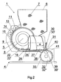
- fig. 2 module of fig. 1 in a simplified side view i.e. a nozzle and fragment of the disc of the supporting element are removed
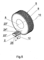
- fig. 3 the cutting drum with the guide element in form of a multi flute shaft and the set of the segments in a perspective view
- fig. 4 fragmentary view of fig. 3 showing the guide element in enlargement in cross section, fig.
- the apparatus presented in an exemplary embodiment consists of four similar modules 1, which does not confine the application of any number of modules 1, the number of which is defined by the contents of segments 2 in a cigarette filter.
- the apparatus enables preparing and compiling groups 3 of segments 2 according to a continuous endwise manner on an exit path 4 of the apparatus in a process of producing multi segment filters.
- Each module 1 is provided with a cutting drum 5 placed under a container 6 of filter rods 7 of length constituting n-multiplicity of length of the segment 2.
- the cutting drum 5 of a horizontal axis 8 is provided on its periphery with flutes 9 of axes 10 parallel to the axis 8 of the drum 5.
- the chain 18 is guided in a horizontal plane with the aid of sprockets 19 so that the dogs 17 move all the time over a plane parallel to the axis 8 of the cutting drum 5.
- the sprocket 20 before the cutting drum 5 is displaceably arranged which enables required arrangement of the chain 18 dependent on the width of the cutting drum 5 so that the approximate central position of the dog 17 over the front face of the last segment 2 in the set 12 is maintained.
- Each set 12 is positioned in stream of the sets 12 in the guiding channel 21 and is displaced all the time with one dog 17 only.
- a movable guiding element 22 which operates in synchronism with the cutting drum 5 and constitutes a wall which closes the channel 21.
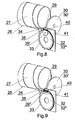
- the guiding element 22 constitutes a rotary multi flute shaft 22', whereas axes 23' of flutes 24' of shaft 22' within the area of guiding the withdrawn set 12 of segments 2 may be parallel to the axis 8 of the cutting drum 5 so that axis 25 of the set 12 is in principle parallel to the axis 5 while drawing the set out of the flute 9 of the cutting drum 5 and the height of the guiding channel 21 is constant.
- the axes 23' of the flutes 24' of the shaft 22' within the area of guiding the drawn set 12 of segments 2 may be askew with reference to the axis 8 of the cutting drum 5 so that the guiding surface of the flute 24' of the shaft 22' is askew with reference to the axis 25 of the set 12 and the height of the guiding channel 21 for the front face of the first segment 2 in the drawn set 12 is constant, whereas the axis 25 of the set 12 while drawing is in principle parallel to the axis 8 of the cutting drum 5.
- the movable guiding element 22 has a form of an endless belt 22" with flutes 24" of axes 23" arranged in general parallel to the axis 8 of the cutting drum 5 in the area of drawing of the set 12 of segments 2.
- a drum 26 which pushes the segments together is positioned over the channel 21, the drum being provided with a worm surface 27, the pitch s of the surface diminishes gradually in the direction of movement of segments 2 from the value which enables interception the set of segments by the worm surface 27 of the set 12 of the segments 2 by the dog 17 of the chain 18, down to the value corresponding to the length of the set 12.
- the axis 28 of the pushing together drum 26 is askew with reference to the axis 25 of the set 12 of the segments 2 displaced along the channel 21 under the pushing together drum 26.
- the worm surface 27 of the pushing together drum 26 intercepts the set 12 of the segments 2 from the dog 17 and pushes the segments 2 in a stream, which is passed over to a guide shoe 29 positioned by the outlet of the guiding channel 21.
- the task for the guide shoe 29 it is to hold up the consecutive segment 2 in the stream of the sets 12 of the segments 2 in the direction of pushing out while separating the preceding segment 2 out of the stream by a separator 30.
- the separator 30 has a form of a disc cam of an axis 31 in principle parallel to the axis of the segment 2 passed for separating which pushes out the segment 2 perpendicular to its axis over a rotary assembled transferring element 32 between two neighbouring drivers 33 spaced radially on the periphery of the transferring element 32.
- a nozzle 34 supplying compressed air directed towards the area between the guide shoe 29 and the separator 30 so that the stream of the air helps separating of the segment 2 and stabilizes the separated segment 2.
- the separator 30 may have a form of a disc cam the periphery of which constitutes a pushing out surface 35 of the segment 2, whereas on the periphery there may be more than one pushing out surface 35, and the said surfaces 35 may be spaced uniformly.
- the separator 30' has a form of a disc cam, the periphery of which constitutes a pushing out surface 35', and moreover it has an abutting surface 36 which determines the axial speed of the segment 2 being separated which is synchronised with the speed imparted on the set 12 of the segments 2 by the worm surface 27 of the pushing together drum 26.
- the said separator 30' may have more than one abutting surface 36 and more than one pushing out surface 35', whereas the said surfaces 36 and 35' may be spaced uniformly and the abutting surface 36 is parallel to the front face of the segment 2 being separated, and the width of the pushing out surface 35' in the last phase of separating the segment 2 is bigger than the length of the segment 2.
- the said transferring element 32 in the periphery area constitutes a unit of two discs 37 slightly spaced at a distance, whereas on each disc 37 there are drivers 33 mounted uniformly and between the discs 37 a height adjustable support 38 is situated.
- the drivers 33 may be mounted on the transferring element 32 in a shifting manner and moreover they may be spaced uniformly or non-uniformly on the periphery of the transferring element 32.
- a movable supporting element 39 In the area of pushing out the separated segment 2 is situated a movable supporting element 39, the speed of which is synchronised with rotations of the transferring element 32, supporting element positioned so that in the area of separating is created a chamber 40 intended to temporarily store the segment 2 till the moment of collecting it by the driver 33, the chamber being defined at the bottom by the top edge of the support 38, on one side by the side of the movable supporting element 39, on the other side by the pushing out surface 35 or 35' of the separator 30 or 30' and at the top by a cover 41 of the transferring element 32.
- the movable supporting element 39 constitutes a disc 39' rotary assembled on the axis perpendicular to the transferring element 32.
- the movable supporting element 39 constitutes an endless belt 39" of the supporting surface parallel to the transferring element 32.
- the apparatus is provided with four modules 1 I , 1 II , 1 III and 1 IV , whereas the outer modules 1 I and 1 IV are provided with the transferring element 32' with drivers 33 spaced uniformly and two inner modules 1 II and 1 III are provided with the transferring element 32" with drivers 33 spaced non-uniformly.
- the segment 2 passed at a uniform rate by the separator 30 or 30' into the chamber 40 of the transferring element 32 is collected by the driver 33 with the delay dependent on the distance between the driver 33 and the front face of the segment 2 and the delay determines the setting of the segment 2 passed by the transferring element 32 on the exit path 4, whereas uniform setting of equal segments 2 of one type is effected with the aid of the outer transferring elements 32' with the drivers 33 spaced uniformly and non-uniform setting of equal segments 2 of one type is effected with the aid of the inner transferring elements 32" with the drivers 33 spaced non-uniformly.
- uniform setting of equal segments 2 of one type is effected with the aid of the outer transferring elements 32' with the drivers 33 spaced uniformly
- non-uniform setting of equal segments 2 of one type is effected with the aid of the inner transferring elements 32" with the drivers 33 spaced non-uniformly.
- segments 2D of double length are transferred uniformly onto the exit path 4 with the aid of the transferring element 32' of the uniformly spaced drivers 33, whereas the distance between the consecutive segments 2D constitutes value z.
- a segment 2C of single length is placed into the area before and after the segment 2D of double length, and then similarly a segment 2B of single length is placed with the aid of the transferring element 32" of the non-uniformly spaced drivers 33 into the area before and after the segment 2C.
Landscapes
- Cigarettes, Filters, And Manufacturing Of Filters (AREA)
- Preparation Of Compounds By Using Micro-Organisms (AREA)
- Prostheses (AREA)
- Superconductors And Manufacturing Methods Therefor (AREA)
- Manufacturing Of Cigar And Cigarette Tobacco (AREA)
- Multi-Process Working Machines And Systems (AREA)
- Control Of Motors That Do Not Use Commutators (AREA)
Claims (15)
- Vorrichtung zum Vorbereiten von Segmenten (2) in Gruppen (3) in einer kontinuierlichen Ende-an-Ende Weise in einem Verfahren zur Herstellung von Multisegment-Filtern, welche als Teil eines Moduls (1;1'1";1III,1IV) eine Schneidwalze (5) mit einer horizontalen Achse (8) mit Rillen (9) mit Achsen (10) parallel zur Achse (8) der Walze (5) aufweist, und die Rillen (9) mit Achsen (10) auf der Umfangsfläche der Walze (5) beabstandet angeordnet sind, wobei die Walze (5) an der Zuführung mit einem Behälter (6) für Filterstränge (7) verbunden ist, und mit der Walze (5) zusammenwirkende kreisförmige Messer (11) aufweist, wobei in Sätze (12) von Segmenten (2) geschnittene Filterstränge (7) mit Hilfe von auf einer Endloskette (18) montierten Nasen (17) aus den Rillen (9) in einen Führungskanal (21) gezogen werden, dessen Bahn im Bereich der aus den Rillen (9) gezogenen Sätzen (12) von Segmenten (2) im Wesentlichen parallel zur Achse (10) einer Rille (9) ist, dadurch gekennzeichnet, dass die Vorrichtung ein bewegliches Führungselement (22) aufweist, das synchron mit der Schneidwalze (5) zusammenarbeitet, bei der Schneidwalze (5) angeordnet ist und eine den Kanal (21) für aus den Rillen (9) der Schneidwalze (5) gezogenen Sätze (12) von Segmenten (2) abschliessende Wand bildet.
- Vorrichtung nach Anspruch 1, wobei darüber hinaus das Modul (1;1'1";1III,1IV) einen Separator (30) aufweist, der zum Vereinzeln einzelner Segmente aus einem Strom der Sätze (12) von Segmenten (2) ausgebildet ist und ferner ein Transferelement (32) aufweist, das zum Sammeln der vereinzelten Segmente (2) und zu deren Ablegen auf einer Austrittsbahn (4) ausgebildet ist.
- Vorrichtung nach Anspruch 2, wobei der mittels der Nase (17) der Kette (18) durch den Kanal (21) geführte Satz (12) von Segmenten (2) von einem über dem Kanal (21) angeordneten Schneckengewinde (27) einer Zusammenschieb-Walze (26) aufgenommen wird, wobei die Zusammenschieb-Walze zum Weitergeben der Segmente (2) zur Vereinzelung ausgebildet ist, und wobei die Ganghöhe (s) des Schneckengewindes (27) in Bewegungsrichtung der Segmente (2) bis hin zu dem Wert abnimmt, welcher der Länge (w) des Satzes (12) von Segmenten (2) entspricht, und der Separator (30) des am Ende des Kanals (21) angeordneten Segments (2) eine Nockenscheibe mit einer zur Achse des zur Vereinzelung geführten Segments (2) im Wesentlichen parallelen Drehachse (31) bildet, wobei die Nockenscheibe zum Ausstossen des Segments (2) in eine Richtung senkrecht zur Achse des zur Vereinzelung auf das drehend montierte Transferelement (32) zwischen zwei auf dem Umfang des Transferelements (32) benachbart angeordnete, radial beabstandete Mitnehmer (33), geführten Segments (2) ausgestaltet ist.
- Vorrichtung nach einem der vorhergehenden Ansprüche, wobei das bewegliche Führungselement (22) eine drehbar montierte Mehrrillen-Welle (22') bildet.
- Vorrichtung nach Anspruch 4, wobei die Achsen (23') der Rillen (24') der Mehrrillen-Welle (22') im Bereich des Führens des Satzes (12) von aus der Walze (5) gezogenen Segmenten (2) parallel zur Achse (8) der Schneidwalze (5) verlaufen, so dass die Achse (25) des Satzes (12) von Segmenten (2) im Grundsatz parallel zur Achse (8) der Schneidwalze (5) ist und die Höhe des Führungskanals (21) konstant ist.
- Vorrichtung nach Anspruch 4, wobei die Achsen (23') der Rillen (24') der Mehrrillen-Welle (22') im Bereich des Führens des Satzes (12) von aus der Walze (5) gezogenen Segmenten (2) schräg zur Achse (8) der Schneidwalze (5) verlaufen, so dass die Führungsfläche der Rille (24') der Welle (22') in Bezug zur Achse (25) des Satzes (12) von Segmenten (2) gekippt ist, und die Höhe des Führungskanals (21) für die Stirnseite des ersten Segments (2) des Satzes (12) von Segmenten (2) konstant ist, während die Achse (25) des Satzes (12) von Segments (2) im Grundsatz parallel zur Achse (8) der Schneidwalze (5) ist.
- Vorrichtung nach Anspruch 1, wobei das bewegliche Führungselement (22) ein Endlosband (22") mit Rillen (24") mit Achsen (23") bildet, welche im Bereich der aus der Walze (5) gezogenen Sätzen (12) von Segmenten (2) im Grundsatz parallel zur Achse (8) der Schneidwalze (5) verlaufen.
- Vorrichtung nach Anspruch 1, wobei die Schneidwalze (5) mit einer am Gehäuse (14) der Walze (5) montierten Abdeckung (15) über dem aktiven Teil der Umfangsfläche der Walze (5) versehen ist, und in der Abdeckung (15) Aussparungen (16) für die kreisförmigen Messer (11) vorgesehen sind, welche auf Achsen (13) einer am Gehäuse (14) der Walze (5) montierten Halterung angeordnet sind.
- Vorrichtung nach Anspruch 1, wobei die Endloskette (18) mit Hilfe von Zahnrädern (19) in einer horizontalen Ebene geführt ist, so dass die in gleichen Abständen auf der Kette (18) montierten Nasen (17) ständig in einer Ebene parallel zur Achse(8) der Schneidwalze (5) versetzt werden, wobei das Zahnrad (20), welches in Führungsrichtung der Kette (18) gesehen vor der Schneidwalze (5) angeordnet ist, versetzbar ist.
- Vorrichtung nach einem der Ansprüche 3 bis 9, wobei individuelle gleichartige Module (1;1'1";1III,1IV) in einer Ende-an-Ende Weise in beliebiger Sequenz angeordnet sind.
- Verfahren zum Zusammenstellen von Gruppen von Segmenten (2) in einer kontinuierlichen Ende-an-Ende Weise in einem Verfahren zur Herstellung von Multisegment-Filtern, wobei das Verfahren die Schritte umfasst:- Zuführen von Filtersträngen (7) auf den Umfang einer Schneidwalze (5), wobei die Schneidwalze (5) eine horizontale Achse (8) mit Rillen (9) mit Achsen (10) parallel zur Achse (8) der Walze (5) aufweist und die Rillen (9) mit Achsen (10) auf dem Umfang der Walze (5) beabstandet angeordnet sind,- Schneiden der Filterstränge in Sätze von Segmenten mit Hilfe von mit der Walze (5) zusammenwirkenden kreisförmigen Messern (11), und- Herausziehen der Sätze von Segmenten (2) aus den Rillen (9) in einen Führungskanal (21),- Abdecken der mittels eines beweglichen Führungselements (22) aus den Rillen (9) der Schneidwalze (5) gezogenen Sätze (12) von Segmenten (2).
- Verfahren nach Anspruch 11, den weiteren Schritt aufweisend, dass das bewegliche Führungselement (22) synchron mit der Schneidwalze (5) zusammenarbeitet, bei der Schneidwalze (5) angeordnet ist und eine den Führungskanal (21) abschliessende Wand bildet.
- Verfahren nach Anspruch 11 oder 12, wobei die in Sätze (12) von Segmenten (2) geschnittenen Filterstränge (7) im Grundsatz parallel zur Achse (10) einer Rille (9) aus den Rillen (9) in den Führungskanal (21) gezogen werden.
- Verfahren nach einem der Ansprüche 11 bis 13, wobei ein Separator (30) einzelne Segmente aus einem Strom der Sätze (12) von Segmenten (2) vereinzelt, und ein Transferelement (32) die vereinzelten Segmente (2) sammelt und auf einer Austrittsbahn (4) ablegt.
- Verfahren nach einem der Ansprüche 11 bis 14, den weiteren Schritt umfassend: Führen der Endloskette (18) in einer horizontalen Ebene mit Hilfe von Zahnrädern (19), dabei Versetzen der in gleichen Abständen auf der Kette (18) montierten Nasen (17) in einer Ebene parallel zu der Achse(8) der Schneidwalze (5) durch Versetzen des Zahnrads (20), welches in Führungsrichtung der Kette (18) gesehen vor der Schneidwalze (5) angeordnet ist.
Priority Applications (1)
| Application Number | Priority Date | Filing Date | Title |
|---|---|---|---|
| PL12154101T PL2449899T3 (pl) | 2007-12-10 | 2008-12-08 | Sposób wytwarzania segmentów w procesie wytwarzania filtrów wielosegmentowych i urządzenie do wytwarzania segmentów w grupach w procesie wytwarzania filtrów wielosegmentowych |
Applications Claiming Priority (2)
| Application Number | Priority Date | Filing Date | Title |
|---|---|---|---|
| PL383995A PL383995A1 (pl) | 2007-12-10 | 2007-12-10 | Sposób zestawiania grup segmentów w procesie wytwarzania filtrów wielosegmentowych oraz urządzenie do przygotowywania i zestawiania w grupy segmentów w procesie wytwarzania filtrów wielosegmentowych |
| EP08860340A EP2230951B1 (de) | 2007-12-10 | 2008-12-08 | Verfahren zum zusammenstellen von gruppen von segmenten in einem verfahren zur herstellung von multisegmentfiltern und apparat zur herstellung und zusammenstellung von segmenten in gruppen in einem verfahren zur herstellung von multisegmentfiltern |
Related Parent Applications (2)
| Application Number | Title | Priority Date | Filing Date |
|---|---|---|---|
| EP08860340A Division EP2230951B1 (de) | 2007-12-10 | 2008-12-08 | Verfahren zum zusammenstellen von gruppen von segmenten in einem verfahren zur herstellung von multisegmentfiltern und apparat zur herstellung und zusammenstellung von segmenten in gruppen in einem verfahren zur herstellung von multisegmentfiltern |
| EP08860340.2 Division | 2008-12-08 |
Publications (2)
| Publication Number | Publication Date |
|---|---|
| EP2449899A1 EP2449899A1 (de) | 2012-05-09 |
| EP2449899B1 true EP2449899B1 (de) | 2014-09-03 |
Family
ID=40379749
Family Applications (2)
| Application Number | Title | Priority Date | Filing Date |
|---|---|---|---|
| EP08860340A Active EP2230951B1 (de) | 2007-12-10 | 2008-12-08 | Verfahren zum zusammenstellen von gruppen von segmenten in einem verfahren zur herstellung von multisegmentfiltern und apparat zur herstellung und zusammenstellung von segmenten in gruppen in einem verfahren zur herstellung von multisegmentfiltern |
| EP12154101.5A Active EP2449899B1 (de) | 2007-12-10 | 2008-12-08 | Verfahren zur Vorbereitung von Segmenten in Gruppen in einem Verfahren zur Herstellung von Multisegmentfiltern und Vorrichtung zur Vorbereitung von Segmenten in Gruppen in einem Verfahren zur Herstellung von Multisegmentfiltern |
Family Applications Before (1)
| Application Number | Title | Priority Date | Filing Date |
|---|---|---|---|
| EP08860340A Active EP2230951B1 (de) | 2007-12-10 | 2008-12-08 | Verfahren zum zusammenstellen von gruppen von segmenten in einem verfahren zur herstellung von multisegmentfiltern und apparat zur herstellung und zusammenstellung von segmenten in gruppen in einem verfahren zur herstellung von multisegmentfiltern |
Country Status (11)
| Country | Link |
|---|---|
| US (2) | US8118721B2 (de) |
| EP (2) | EP2230951B1 (de) |
| JP (1) | JP5281652B2 (de) |
| KR (1) | KR101504386B1 (de) |
| CN (1) | CN101896083B (de) |
| AT (1) | ATE550956T1 (de) |
| BR (1) | BRPI0821000B1 (de) |
| ES (2) | ES2524404T3 (de) |
| PL (3) | PL383995A1 (de) |
| TW (1) | TWI452972B (de) |
| WO (1) | WO2009074540A1 (de) |
Cited By (1)
| Publication number | Priority date | Publication date | Assignee | Title |
|---|---|---|---|---|
| WO2025032065A1 (en) | 2023-08-08 | 2025-02-13 | Philip Morris Products S.A. | Positioning of segments for aerosol-generating articles with a positioning wheel having adjustable receiving positions |
Families Citing this family (67)
| Publication number | Priority date | Publication date | Assignee | Title |
|---|---|---|---|---|
| IT1392375B1 (it) * | 2008-07-18 | 2012-03-02 | Gd Spa | Macchina confezionatrice per la produzione di filtri combinati per sigarette. |
| US8808153B2 (en) * | 2009-07-14 | 2014-08-19 | Aiger Group Ag | Apparatus for assembly of multi-segment rod-like articles |
| PL388549A1 (pl) | 2009-07-15 | 2011-01-17 | International Tobacco Machinery Poland Spółka Z Ograniczoną Odpowiedzialnością | Sposób bezpiecznego przekazywania segmentów filtrowych w procesie wytwarzania filtrów wielosegmentowych |
| IT1395035B1 (it) * | 2009-08-10 | 2012-09-05 | Gd Spa | Macchina a doppia linea e metodo per la realizzazione di filtri composti per sigarette, sigari o simili. |
| US8303474B2 (en) * | 2009-08-31 | 2012-11-06 | Aiger Group Ag | Apparatus and method for insertion of capsules into filter tows |
| US20110162662A1 (en) * | 2010-01-05 | 2011-07-07 | Aiger Group Ag | Apparatus and method for insertion of capsules into filter tows |
| US9131730B2 (en) * | 2010-01-07 | 2015-09-15 | Aiger Group Ag | System and apparatus for registration of different objects in rod shaped articles |
| IT1398917B1 (it) * | 2010-03-02 | 2013-03-28 | Montrade S R L | Macchina per la realizzazione di filtri di sigaretta |
| IT1398246B1 (it) * | 2010-03-09 | 2013-02-22 | Montrade S R L | Macchina per la realizzazione di filtri di sigaretta. |
| US9623988B2 (en) | 2010-03-26 | 2017-04-18 | Philip Morris Usa Inc. | High speed poucher |
| PL390871A1 (pl) * | 2010-03-29 | 2011-10-10 | International Tobacco Machinery Poland Spółka Z Ograniczoną Odpowiedzialnością | Sposób kompensacji chwilowego braku segmentów filtrowych w linii wytwarzania filtrów wielosegmentowych oraz urządzenie umożliwiające kompensację chwilowego braku segmentów filtrowych w linii wytwarzania filtrów wielosegmentowych |
| PL217430B1 (pl) * | 2010-05-06 | 2014-07-31 | Int Tobacco Machinery Poland | Sposób ustalania wzajemnego położenia segmentów filtrowych na elemencie nośnym zespołu grupującego w procesie wytwarzania filtrów wielosegmentowych |
| CN102258217A (zh) * | 2010-05-27 | 2011-11-30 | 上海方禹机电科技有限公司 | 用于滤棒复合的传送装置及传送方法 |
| IT1400727B1 (it) * | 2010-07-08 | 2013-07-02 | Gd Spa | Macchina e metodo per la produzione di filtri composti. |
| IT1401045B1 (it) * | 2010-07-15 | 2013-07-12 | Gd Spa | Macchina e metodo per la realizzazione di filtri composti. |
| US8622882B2 (en) | 2010-09-27 | 2014-01-07 | Aiger Group Ag | Apparatus and method for insertion of capsules into filter tows |
| US8475348B2 (en) | 2010-09-28 | 2013-07-02 | Aiger Group Ag | Apparatus and method for assembly of multi-segment rod-like articles |
| TW201238505A (en) * | 2010-12-03 | 2012-10-01 | Philip Morris Prod | Combiner for rod-shaped articles |
| US9232820B2 (en) | 2011-03-25 | 2016-01-12 | Hauni Maschinenbau Ag | High speed object inserter and related methods |
| US9055768B2 (en) | 2011-03-25 | 2015-06-16 | Hauni Maschinenbau Ag | High speed object inserter and related methods |
| PL394455A1 (pl) * | 2011-04-06 | 2012-10-08 | International Tobacco Machinery Poland Spólka Z Ograniczona Odpowiedzialnoscia | Urzadzenie do przemieszczania segmentów filtrowych w procesie wytwarzania filtrów wielosegmentowych |
| PL219049B1 (pl) | 2011-05-23 | 2015-03-31 | Int Tobacco Machinery Poland | Zespół do przemieszczania segmentów filtrowych |
| PL219048B1 (pl) | 2011-05-23 | 2015-03-31 | Int Tobacco Machinery Poland | Odłączalna głowica tnąca do urządzenia do podawania zestawów segmentów filtrowych, urządzenie napędowe do odłączalnej głowicy tnącej i sposób wymiany odłączalnej głowicy tnącej |
| EP2713781B1 (de) | 2011-06-03 | 2026-02-11 | Tobacco Research And Development Institute (Proprietary) Limited | Modulares gerät zur herstellung von rauchwaren |
| HUE026545T2 (hu) * | 2011-07-25 | 2016-06-28 | Philip Morris Products Sa | Továbbító berendezés és eljárás tárgyak továbbítására |
| DE102011113648A1 (de) | 2011-09-19 | 2013-03-21 | Hauni Maschinenbau Ag | Multifilterherstellmodul |
| US9063629B2 (en) * | 2011-10-31 | 2015-06-23 | Nokia Technologies Oy | Responding to a received message in a locked user interaction mode |
| PL219777B1 (pl) | 2012-03-26 | 2015-07-31 | Int Tobacco Machinery Poland | Układ czyszczący do transportera bębnowego urządzenia do podawania segmentów filtrowych do urządzenia produkującego filtry wielosegmentowe oraz sposób czyszczenia transportera bębnowego |
| CN104379004B (zh) | 2012-04-30 | 2019-12-06 | 菲利普莫里斯生产公司 | 两部分多部件组合机 |
| DE102012208604A1 (de) | 2012-05-23 | 2013-11-28 | Hauni Maschinenbau Ag | Einrichtung zum Schneiden von Filterstäben |
| BR112015013146B1 (pt) | 2012-12-06 | 2021-03-02 | British American Tobacco (Investments) Limited | aparelho modular para a fabricação de artigo de fumar, aparelho de montagem de artigo de fumar, kit, método de reconfiguração de um aparelho modular |
| GB201321920D0 (en) * | 2013-12-11 | 2014-01-22 | British American Tobacco Co | A method and apparatus for inserting elongate elements into a sleeve |
| WO2016042101A1 (en) | 2014-09-19 | 2016-03-24 | Philip Morris Products S.A. | Method and apparatus for intermediately storing double-length semi-finished products |
| US20160120213A1 (en) | 2014-10-31 | 2016-05-05 | R. J. Reynolds Tobacco Company | Tobacco product component recovery system |
| EP3348153A1 (de) * | 2014-12-02 | 2018-07-18 | MONTRADE S.p.A. | Maschine und verfahren, in dem material auf ein sich bewegendes substrat entladen wird |
| EP3297458B2 (de) | 2015-05-21 | 2024-02-14 | Philip Morris Products S.A. | Verfahren zur herstellung induktiv erwärmbarer tabakstränge |
| HUE034707T2 (hu) | 2015-07-16 | 2018-02-28 | Int Tobacco Machinery Poland Sp Zoo | Átviteli tárcsa és annak használata |
| CN105253584A (zh) * | 2015-09-28 | 2016-01-20 | 青岛萨沃特自动化设备有限公司 | 自动物料整理装置 |
| US10058125B2 (en) | 2015-10-13 | 2018-08-28 | Rai Strategic Holdings, Inc. | Method for assembling an aerosol delivery device |
| PL3172976T3 (pl) * | 2015-11-24 | 2018-05-30 | International Tobacco Machinery Poland Sp. Z O.O. | Sposób i system wytwarzania artykułów prętopodobnych |
| US10314334B2 (en) | 2015-12-10 | 2019-06-11 | R.J. Reynolds Tobacco Company | Smoking article |
| WO2017114959A1 (en) * | 2015-12-30 | 2017-07-06 | Philip Morris Products S.A. | Feeder for components of an aerosol forming article |
| US10285433B2 (en) | 2016-01-21 | 2019-05-14 | R.J. Reynolds Tobacco Company | Capsule object rupture testing system and associated method |
| WO2017187501A1 (ja) * | 2016-04-26 | 2017-11-02 | 日本たばこ産業株式会社 | フィルタセグメントフィーダ |
| PL239184B1 (pl) * | 2016-09-09 | 2021-11-15 | Int Tobacco Machinery Poland Spolka Z Ograniczona Odpowiedzialnoscia | Zespół podający, urządzenie podające, podajnik i sposób podawania artykułów prętopodobnych |
| PL238818B1 (pl) | 2017-05-29 | 2021-10-11 | Int Tabacco Machinery Poland Spolka Z Ograniczona Odpowiedzialnoscia | Urządzenie transferujące do transferowania i sposób transferowania artykułów prętopodobnych przemysłu tytoniowego oraz urządzenie do konwersji konfiguracji strumienia takich artykułów |
| PL239188B1 (pl) * | 2017-12-03 | 2021-11-15 | Int Tobacco Machinery Poland Spolka Z Ograniczona Odpowiedzialnoscia | Urządzenie uzupełniające, maszyna do wytwarzania sztabek wielosegmentowych i sposób wytwarzania sztabek wielosegmentowych |
| US10786010B2 (en) | 2017-12-15 | 2020-09-29 | Rai Strategic Holdings, Inc. | Aerosol delivery device with multiple aerosol delivery pathways |
| US10375986B1 (en) | 2018-02-28 | 2019-08-13 | Altria Client Services Llc | Spacing drum and method |
| KR102190097B1 (ko) * | 2018-04-04 | 2020-12-11 | 이정수 | 향 필터 제조방법 |
| PL242031B1 (pl) * | 2018-04-04 | 2023-01-09 | International Tobacco Machinery Poland Spółka Z Ograniczoną Odpowiedzialnością | Sposób i urządzenie do transportowania artykułów prętopodobnych przemysłu tytoniowego |
| PL3549458T3 (pl) | 2018-04-04 | 2021-06-14 | International Tobacco Machinery Poland Sp. Z O.O. | Sposób i urządzenie do transportowania artykułów prętopodobnych przemysłu tytoniowego |
| KR101946198B1 (ko) * | 2018-04-06 | 2019-02-08 | 이정수 | 전자담배 제조장치 |
| KR102933407B1 (ko) | 2018-05-21 | 2026-03-03 | 제이티 인터내셔널 소시에떼 아노님 | 에어로졸 발생 물품을 제조하기 위한 방법 및 장치 |
| US11033049B2 (en) | 2018-08-01 | 2021-06-15 | R.J. Reynolds Tobacco Company | Apparatus for recovering tobacco material and related method |
| CN109761068A (zh) * | 2019-01-18 | 2019-05-17 | 郑州海意科技有限公司 | 一种滤棒检测装置 |
| CN110076831A (zh) * | 2019-03-19 | 2019-08-02 | 东莞市香草生物工程有限公司 | 一种自动卷烟分切机 |
| CN110419771B (zh) * | 2019-08-15 | 2022-04-19 | 襄阳申冠机电技术有限公司 | 棒状物料传递装置 |
| US11571015B2 (en) * | 2019-08-23 | 2023-02-07 | Altria Client Services Llc | Methods of assembling filters and spacing drum systems thereof |
| EP3808192A1 (de) * | 2019-10-16 | 2021-04-21 | International Tobacco Machinery Poland SP. Z O.O. | Maschine zur herstellung von filterstäben |
| EP3811792B1 (de) | 2019-10-21 | 2022-07-06 | International Tobacco Machinery Poland Sp. z o.o. | Zuführvorrichtung zur zuführung eines tabakindustriesegments |
| PL244133B1 (pl) * | 2020-05-14 | 2023-12-04 | Int Tobacco Machinery Poland Spolka Z Ograniczona Odpowiedzialnoscia | Urządzenie do formowania końcówek artykułu prętopodobnego, urządzenie do produkcji artykułów prętopodobnych i sposób formowania końcówek artykułu prętoopdobnego dla przemysłu tytoniowego |
| PL442929A1 (pl) * | 2022-11-24 | 2024-05-27 | International Tobacco Machinery Poland Spółka Z Ograniczoną Odpowiedzialnością | Moduł zasilający do podawania segmentów, urządzenie do wytwarzania artykułów wielosegmentowych i sposób podawania segmentów do wytwarzania artykułów wielosegmentowych |
| PL442927A1 (pl) * | 2022-11-24 | 2024-05-27 | International Tobacco Machinery Poland Spółka Z Ograniczoną Odpowiedzialnością | Urządzenie i sposób do wytwarzania artykułów wielosegmentowych |
| PL442928A1 (pl) * | 2022-11-24 | 2024-05-27 | International Tobacco Machinery Poland Spółka Z Ograniczoną Odpowiedzialnością | Moduł zasilający do zasilania segmentami w postaci artykułów prętopodobnych, urządzenie i sposób do wytwarzania artykułów wielosegmentowych |
| EP4374714A1 (de) | 2022-11-24 | 2024-05-29 | International Tobacco Machinery Poland Sp. z o.o. | Zuführmodul zum zuführen von segmenten in form von stabförmigen artikeln, vorrichtung und verfahren zur herstellung von mehrsegmentartikeln |
| PL448661A1 (pl) * | 2024-05-28 | 2025-12-01 | International Tobacco Machinery Poland Spółka Z Ograniczoną Odpowiedzialnością | Urządzenie transportowo-tnące przemysłu tytoniowego do przenoszenia i cięcia sztabek |
Family Cites Families (21)
| Publication number | Priority date | Publication date | Assignee | Title |
|---|---|---|---|---|
| US2882970A (en) * | 1956-04-18 | 1959-04-21 | Olin Mathieson | Laminated filter tip |
| GB876733A (en) * | 1957-02-20 | 1961-09-06 | Norman Walter Jackson | Improvements in or relating to apparatus for making mouthpiece cigarettes |
| GB915203A (en) * | 1958-02-27 | 1963-01-09 | Desmond Walter Molins | Improvements in or relating to the manufacture of composite mouthpieces for cigarettes |
| DE1096272B (de) * | 1958-06-28 | 1960-12-29 | Hauni Werke Koerber & Co Kg | Verfahren zum Herstellen von Filtermundstueckzigaretten |
| DE1156008B (de) * | 1958-11-25 | 1963-10-17 | Hauni Werke Koerber & Co Kg | Zwischenfoerderer zum queraxial erfolgenden UEbertragen unter gleichzeitigem axialen Bewegen von Filtern oder anderen stabfoermigen Gegenstaenden |
| GB971491A (en) | 1959-11-26 | 1964-09-30 | Tom Rowlands | Improvements in or relating to the production of mouthpieces for cigarettes |
| GB1054545A (de) * | 1962-10-05 | |||
| GB1087545A (en) * | 1963-11-11 | 1967-10-18 | Korber Kurt | Method and apparatus for manipulating rod-like articles such as filter plugs or the like |
| US3357320A (en) * | 1965-02-05 | 1967-12-12 | Brown & Williamson Tobacco Corp | Multiple filter assembly apparatus |
| GB1235842A (en) * | 1967-07-12 | 1971-06-16 | Molins Machine Co Ltd | Improvements in or relating to handling rod-like articles |
| GB1576212A (en) * | 1976-06-19 | 1980-10-01 | Molins Ltd | Apparatus for feeding wrapper material |
| GB1578738A (en) * | 1976-07-22 | 1980-11-05 | Molins Ltd | Apparatus for assembling rod-like articles |
| GB1597499A (en) * | 1977-04-30 | 1981-09-09 | Molins Ltd | Method and apparatus for forming composite rods |
| DE2804991A1 (de) * | 1978-02-06 | 1979-08-16 | Hauni Werke Koerber & Co Kg | Filterzigarette mit einem aus mindestens zwei filterkomponenten bestehenden mundstueck, verfahren zur herstellung einer filterzigarette und vorrichtung zum ausueben des verfahrens |
| DE2806552C2 (de) * | 1978-02-16 | 1986-12-11 | Hauni-Werke Körber & Co KG, 2050 Hamburg | Verfahren und Anordnung zum Überwachen der Herstellung von Kombinationsfiltern für Rauchartikel im Strangverfahren |
| US4411640A (en) * | 1981-01-08 | 1983-10-25 | Liggett Group Inc. | Apparatus for the production of cigarette filter tips having multi-sectional construction |
| DE10146992A1 (de) * | 2001-09-18 | 2003-04-03 | Hauni Maschinenbau Ag | Übergabeeinrichtung und Muldentrommel sowie Verfahren zur Übergabe von Hartfilterlementen |
| DE10146019A1 (de) * | 2001-09-18 | 2003-04-03 | Hauni Maschinenbau Ag | Einrichtung zum Zusammenstellen von Gruppen von Filtersegmenten zur Herstellung von Multisegmentfiltern der tabakverarbeitenden Industrie und Muldentrommel |
| US20040139977A1 (en) * | 2003-01-17 | 2004-07-22 | Garthaffner Martin T. | Degradable slitted cigarette filter |
| JP2005089190A (ja) * | 2003-09-16 | 2005-04-07 | Hauni Maschinenbau Ag | 棒状の物品を引き渡すための装置及び方法 |
| WO2006004111A1 (ja) * | 2004-07-07 | 2006-01-12 | Japan Tobacco Inc. | フィルタロッドの製造機 |
-
2007
- 2007-12-10 PL PL383995A patent/PL383995A1/pl not_active Application Discontinuation
-
2008
- 2008-12-08 PL PL08860340T patent/PL2230951T3/pl unknown
- 2008-12-08 KR KR1020107015072A patent/KR101504386B1/ko not_active Expired - Fee Related
- 2008-12-08 BR BRPI0821000-4A patent/BRPI0821000B1/pt not_active IP Right Cessation
- 2008-12-08 AT AT08860340T patent/ATE550956T1/de active
- 2008-12-08 ES ES12154101.5T patent/ES2524404T3/es active Active
- 2008-12-08 CN CN2008801200205A patent/CN101896083B/zh active Active
- 2008-12-08 JP JP2010537403A patent/JP5281652B2/ja not_active Expired - Fee Related
- 2008-12-08 PL PL12154101T patent/PL2449899T3/pl unknown
- 2008-12-08 WO PCT/EP2008/067032 patent/WO2009074540A1/en not_active Ceased
- 2008-12-08 TW TW097147632A patent/TWI452972B/zh not_active IP Right Cessation
- 2008-12-08 EP EP08860340A patent/EP2230951B1/de active Active
- 2008-12-08 EP EP12154101.5A patent/EP2449899B1/de active Active
- 2008-12-08 ES ES08860340T patent/ES2385128T3/es active Active
- 2008-12-10 US US12/331,853 patent/US8118721B2/en active Active
-
2012
- 2012-02-08 US US13/368,841 patent/US8353810B2/en active Active
Cited By (1)
| Publication number | Priority date | Publication date | Assignee | Title |
|---|---|---|---|---|
| WO2025032065A1 (en) | 2023-08-08 | 2025-02-13 | Philip Morris Products S.A. | Positioning of segments for aerosol-generating articles with a positioning wheel having adjustable receiving positions |
Also Published As
| Publication number | Publication date |
|---|---|
| EP2230951A1 (de) | 2010-09-29 |
| EP2230951B1 (de) | 2012-03-28 |
| ES2524404T3 (es) | 2014-12-09 |
| PL2230951T3 (pl) | 2012-09-28 |
| US8353810B2 (en) | 2013-01-15 |
| ATE550956T1 (de) | 2012-04-15 |
| JP2011505818A (ja) | 2011-03-03 |
| EP2449899A1 (de) | 2012-05-09 |
| PL383995A1 (pl) | 2009-06-22 |
| JP5281652B2 (ja) | 2013-09-04 |
| CN101896083A (zh) | 2010-11-24 |
| KR101504386B1 (ko) | 2015-03-19 |
| US8118721B2 (en) | 2012-02-21 |
| BRPI0821000B1 (pt) | 2019-04-09 |
| US20090145449A1 (en) | 2009-06-11 |
| PL2449899T3 (pl) | 2015-03-31 |
| CN101896083B (zh) | 2012-10-03 |
| BRPI0821000A2 (pt) | 2015-06-16 |
| TW200936064A (en) | 2009-09-01 |
| ES2385128T3 (es) | 2012-07-18 |
| TWI452972B (zh) | 2014-09-21 |
| KR20100094563A (ko) | 2010-08-26 |
| US20120157278A1 (en) | 2012-06-21 |
| WO2009074540A1 (en) | 2009-06-18 |
Similar Documents
| Publication | Publication Date | Title |
|---|---|---|
| EP2449899B1 (de) | Verfahren zur Vorbereitung von Segmenten in Gruppen in einem Verfahren zur Herstellung von Multisegmentfiltern und Vorrichtung zur Vorbereitung von Segmenten in Gruppen in einem Verfahren zur Herstellung von Multisegmentfiltern | |
| EP2617302B1 (de) | Verfahren und Einheit zur Zuführung von Kügelchen | |
| EP2622973B1 (de) | Kügelchenzuführungsverfahren und Kügelchenzuführungseinheit | |
| RU2447818C2 (ru) | Устройство для разрезания компонентов фильтра | |
| JP4630548B2 (ja) | たばこ加工産業のマルチセグメントフィルタを製造するためにフィルタセグメントのグループを編成する装置とトラフドラム | |
| EP2682010B1 (de) | Verfahren und Vorrichtung zum ungleichmäßigen Überführen von Perlen | |
| EP3122667B1 (de) | Zuführeinheit | |
| EP2145552A2 (de) | Maschine zum Herstellen von Multisegmentfiltern für Zigaretten | |
| EP3122665B1 (de) | Zuführeinheit | |
| EP3122666B1 (de) | Zuführeinheit | |
| EP3122664B1 (de) | Zuführeinheit | |
| DK160178B (da) | Apparat til fremstilling af render i en filterstang | |
| WO2016142500A1 (en) | A filling unit for a loose material and a method for feeding a loose material | |
| CN114052286A (zh) | 用于进给珠状物的进给单元以及用于制造杆的设备 | |
| HK1233603B (en) | Feed unit | |
| HK1233603A1 (en) | Feed unit |
Legal Events
| Date | Code | Title | Description |
|---|---|---|---|
| PUAI | Public reference made under article 153(3) epc to a published international application that has entered the european phase |
Free format text: ORIGINAL CODE: 0009012 |
|
| AC | Divisional application: reference to earlier application |
Ref document number: 2230951 Country of ref document: EP Kind code of ref document: P |
|
| AK | Designated contracting states |
Kind code of ref document: A1 Designated state(s): AT BE BG CH CY CZ DE DK EE ES FI FR GB GR HR HU IE IS IT LI LT LU LV MC MT NL NO PL PT RO SE SI SK TR |
|
| 17P | Request for examination filed |
Effective date: 20121030 |
|
| GRAP | Despatch of communication of intention to grant a patent |
Free format text: ORIGINAL CODE: EPIDOSNIGR1 |
|
| INTG | Intention to grant announced |
Effective date: 20131016 |
|
| GRAP | Despatch of communication of intention to grant a patent |
Free format text: ORIGINAL CODE: EPIDOSNIGR1 |
|
| INTG | Intention to grant announced |
Effective date: 20140318 |
|
| GRAS | Grant fee paid |
Free format text: ORIGINAL CODE: EPIDOSNIGR3 |
|
| GRAA | (expected) grant |
Free format text: ORIGINAL CODE: 0009210 |
|
| AC | Divisional application: reference to earlier application |
Ref document number: 2230951 Country of ref document: EP Kind code of ref document: P |
|
| AK | Designated contracting states |
Kind code of ref document: B1 Designated state(s): AT BE BG CH CY CZ DE DK EE ES FI FR GB GR HR HU IE IS IT LI LT LU LV MC MT NL NO PL PT RO SE SI SK TR |
|
| REG | Reference to a national code |
Ref country code: GB Ref legal event code: FG4D |
|
| REG | Reference to a national code |
Ref country code: AT Ref legal event code: REF Ref document number: 685082 Country of ref document: AT Kind code of ref document: T Effective date: 20140915 Ref country code: CH Ref legal event code: EP |
|
| REG | Reference to a national code |
Ref country code: IE Ref legal event code: FG4D |
|
| REG | Reference to a national code |
Ref country code: CH Ref legal event code: NV Representative=s name: BOHEST AG, CH |
|
| REG | Reference to a national code |
Ref country code: DE Ref legal event code: R096 Ref document number: 602008034291 Country of ref document: DE Effective date: 20141016 |
|
| REG | Reference to a national code |
Ref country code: ES Ref legal event code: FG2A Ref document number: 2524404 Country of ref document: ES Kind code of ref document: T3 Effective date: 20141209 |
|
| REG | Reference to a national code |
Ref country code: NL Ref legal event code: T3 |
|
| REG | Reference to a national code |
Ref country code: AT Ref legal event code: MK05 Ref document number: 685082 Country of ref document: AT Kind code of ref document: T Effective date: 20140903 |
|
| PG25 | Lapsed in a contracting state [announced via postgrant information from national office to epo] |
Ref country code: SE Free format text: LAPSE BECAUSE OF FAILURE TO SUBMIT A TRANSLATION OF THE DESCRIPTION OR TO PAY THE FEE WITHIN THE PRESCRIBED TIME-LIMIT Effective date: 20140903 Ref country code: FI Free format text: LAPSE BECAUSE OF FAILURE TO SUBMIT A TRANSLATION OF THE DESCRIPTION OR TO PAY THE FEE WITHIN THE PRESCRIBED TIME-LIMIT Effective date: 20140903 Ref country code: NO Free format text: LAPSE BECAUSE OF FAILURE TO SUBMIT A TRANSLATION OF THE DESCRIPTION OR TO PAY THE FEE WITHIN THE PRESCRIBED TIME-LIMIT Effective date: 20141203 Ref country code: GR Free format text: LAPSE BECAUSE OF FAILURE TO SUBMIT A TRANSLATION OF THE DESCRIPTION OR TO PAY THE FEE WITHIN THE PRESCRIBED TIME-LIMIT Effective date: 20141204 Ref country code: LT Free format text: LAPSE BECAUSE OF FAILURE TO SUBMIT A TRANSLATION OF THE DESCRIPTION OR TO PAY THE FEE WITHIN THE PRESCRIBED TIME-LIMIT Effective date: 20140903 |
|
| REG | Reference to a national code |
Ref country code: LT Ref legal event code: MG4D |
|
| PG25 | Lapsed in a contracting state [announced via postgrant information from national office to epo] |
Ref country code: HR Free format text: LAPSE BECAUSE OF FAILURE TO SUBMIT A TRANSLATION OF THE DESCRIPTION OR TO PAY THE FEE WITHIN THE PRESCRIBED TIME-LIMIT Effective date: 20140903 Ref country code: CY Free format text: LAPSE BECAUSE OF FAILURE TO SUBMIT A TRANSLATION OF THE DESCRIPTION OR TO PAY THE FEE WITHIN THE PRESCRIBED TIME-LIMIT Effective date: 20140903 Ref country code: LV Free format text: LAPSE BECAUSE OF FAILURE TO SUBMIT A TRANSLATION OF THE DESCRIPTION OR TO PAY THE FEE WITHIN THE PRESCRIBED TIME-LIMIT Effective date: 20140903 Ref country code: AT Free format text: LAPSE BECAUSE OF FAILURE TO SUBMIT A TRANSLATION OF THE DESCRIPTION OR TO PAY THE FEE WITHIN THE PRESCRIBED TIME-LIMIT Effective date: 20140903 |
|
| REG | Reference to a national code |
Ref country code: PL Ref legal event code: T3 |
|
| REG | Reference to a national code |
Ref country code: HU Ref legal event code: AG4A Ref document number: E022396 Country of ref document: HU |
|
| PG25 | Lapsed in a contracting state [announced via postgrant information from national office to epo] |
Ref country code: EE Free format text: LAPSE BECAUSE OF FAILURE TO SUBMIT A TRANSLATION OF THE DESCRIPTION OR TO PAY THE FEE WITHIN THE PRESCRIBED TIME-LIMIT Effective date: 20140903 Ref country code: PT Free format text: LAPSE BECAUSE OF FAILURE TO SUBMIT A TRANSLATION OF THE DESCRIPTION OR TO PAY THE FEE WITHIN THE PRESCRIBED TIME-LIMIT Effective date: 20150105 Ref country code: RO Free format text: LAPSE BECAUSE OF FAILURE TO SUBMIT A TRANSLATION OF THE DESCRIPTION OR TO PAY THE FEE WITHIN THE PRESCRIBED TIME-LIMIT Effective date: 20140903 Ref country code: IS Free format text: LAPSE BECAUSE OF FAILURE TO SUBMIT A TRANSLATION OF THE DESCRIPTION OR TO PAY THE FEE WITHIN THE PRESCRIBED TIME-LIMIT Effective date: 20150103 Ref country code: CZ Free format text: LAPSE BECAUSE OF FAILURE TO SUBMIT A TRANSLATION OF THE DESCRIPTION OR TO PAY THE FEE WITHIN THE PRESCRIBED TIME-LIMIT Effective date: 20140903 Ref country code: SK Free format text: LAPSE BECAUSE OF FAILURE TO SUBMIT A TRANSLATION OF THE DESCRIPTION OR TO PAY THE FEE WITHIN THE PRESCRIBED TIME-LIMIT Effective date: 20140903 |
|
| REG | Reference to a national code |
Ref country code: DE Ref legal event code: R097 Ref document number: 602008034291 Country of ref document: DE |
|
| PG25 | Lapsed in a contracting state [announced via postgrant information from national office to epo] |
Ref country code: BE Free format text: LAPSE BECAUSE OF NON-PAYMENT OF DUE FEES Effective date: 20141231 |
|
| PLBE | No opposition filed within time limit |
Free format text: ORIGINAL CODE: 0009261 |
|
| STAA | Information on the status of an ep patent application or granted ep patent |
Free format text: STATUS: NO OPPOSITION FILED WITHIN TIME LIMIT |
|
| PG25 | Lapsed in a contracting state [announced via postgrant information from national office to epo] |
Ref country code: DK Free format text: LAPSE BECAUSE OF FAILURE TO SUBMIT A TRANSLATION OF THE DESCRIPTION OR TO PAY THE FEE WITHIN THE PRESCRIBED TIME-LIMIT Effective date: 20140903 Ref country code: LU Free format text: LAPSE BECAUSE OF FAILURE TO SUBMIT A TRANSLATION OF THE DESCRIPTION OR TO PAY THE FEE WITHIN THE PRESCRIBED TIME-LIMIT Effective date: 20141208 |
|
| 26N | No opposition filed |
Effective date: 20150604 |
|
| REG | Reference to a national code |
Ref country code: IE Ref legal event code: MM4A |
|
| PG25 | Lapsed in a contracting state [announced via postgrant information from national office to epo] |
Ref country code: IE Free format text: LAPSE BECAUSE OF NON-PAYMENT OF DUE FEES Effective date: 20141208 |
|
| PG25 | Lapsed in a contracting state [announced via postgrant information from national office to epo] |
Ref country code: SI Free format text: LAPSE BECAUSE OF FAILURE TO SUBMIT A TRANSLATION OF THE DESCRIPTION OR TO PAY THE FEE WITHIN THE PRESCRIBED TIME-LIMIT Effective date: 20140903 |
|
| REG | Reference to a national code |
Ref country code: FR Ref legal event code: PLFP Year of fee payment: 8 |
|
| PG25 | Lapsed in a contracting state [announced via postgrant information from national office to epo] |
Ref country code: MC Free format text: LAPSE BECAUSE OF FAILURE TO SUBMIT A TRANSLATION OF THE DESCRIPTION OR TO PAY THE FEE WITHIN THE PRESCRIBED TIME-LIMIT Effective date: 20140903 Ref country code: BG Free format text: LAPSE BECAUSE OF FAILURE TO SUBMIT A TRANSLATION OF THE DESCRIPTION OR TO PAY THE FEE WITHIN THE PRESCRIBED TIME-LIMIT Effective date: 20140903 |
|
| PG25 | Lapsed in a contracting state [announced via postgrant information from national office to epo] |
Ref country code: BE Free format text: LAPSE BECAUSE OF FAILURE TO SUBMIT A TRANSLATION OF THE DESCRIPTION OR TO PAY THE FEE WITHIN THE PRESCRIBED TIME-LIMIT Effective date: 20140903 Ref country code: MT Free format text: LAPSE BECAUSE OF FAILURE TO SUBMIT A TRANSLATION OF THE DESCRIPTION OR TO PAY THE FEE WITHIN THE PRESCRIBED TIME-LIMIT Effective date: 20140903 |
|
| REG | Reference to a national code |
Ref country code: FR Ref legal event code: PLFP Year of fee payment: 9 |
|
| REG | Reference to a national code |
Ref country code: FR Ref legal event code: PLFP Year of fee payment: 10 |
|
| PGFP | Annual fee paid to national office [announced via postgrant information from national office to epo] |
Ref country code: HU Payment date: 20191216 Year of fee payment: 12 |
|
| PGFP | Annual fee paid to national office [announced via postgrant information from national office to epo] |
Ref country code: FR Payment date: 20191220 Year of fee payment: 12 |
|
| PGFP | Annual fee paid to national office [announced via postgrant information from national office to epo] |
Ref country code: TR Payment date: 20191205 Year of fee payment: 12 |
|
| PGFP | Annual fee paid to national office [announced via postgrant information from national office to epo] |
Ref country code: ES Payment date: 20200121 Year of fee payment: 12 |
|
| PG25 | Lapsed in a contracting state [announced via postgrant information from national office to epo] |
Ref country code: HU Free format text: LAPSE BECAUSE OF NON-PAYMENT OF DUE FEES Effective date: 20201209 Ref country code: FR Free format text: LAPSE BECAUSE OF NON-PAYMENT OF DUE FEES Effective date: 20201231 |
|
| REG | Reference to a national code |
Ref country code: ES Ref legal event code: FD2A Effective date: 20220209 |
|
| PG25 | Lapsed in a contracting state [announced via postgrant information from national office to epo] |
Ref country code: ES Free format text: LAPSE BECAUSE OF NON-PAYMENT OF DUE FEES Effective date: 20201209 |
|
| PGFP | Annual fee paid to national office [announced via postgrant information from national office to epo] |
Ref country code: NL Payment date: 20221222 Year of fee payment: 15 |
|
| P01 | Opt-out of the competence of the unified patent court (upc) registered |
Effective date: 20230529 |
|
| REG | Reference to a national code |
Ref country code: NL Ref legal event code: MM Effective date: 20240101 |
|
| PG25 | Lapsed in a contracting state [announced via postgrant information from national office to epo] |
Ref country code: NL Free format text: LAPSE BECAUSE OF NON-PAYMENT OF DUE FEES Effective date: 20240101 |
|
| PG25 | Lapsed in a contracting state [announced via postgrant information from national office to epo] |
Ref country code: TR Free format text: LAPSE BECAUSE OF NON-PAYMENT OF DUE FEES Effective date: 20201208 Ref country code: NL Free format text: LAPSE BECAUSE OF NON-PAYMENT OF DUE FEES Effective date: 20240101 |
|
| PGFP | Annual fee paid to national office [announced via postgrant information from national office to epo] |
Ref country code: DE Payment date: 20241210 Year of fee payment: 17 |
|
| PGFP | Annual fee paid to national office [announced via postgrant information from national office to epo] |
Ref country code: PL Payment date: 20241128 Year of fee payment: 17 |
|
| PGFP | Annual fee paid to national office [announced via postgrant information from national office to epo] |
Ref country code: GB Payment date: 20241224 Year of fee payment: 17 |
|
| PGFP | Annual fee paid to national office [announced via postgrant information from national office to epo] |
Ref country code: CH Payment date: 20250101 Year of fee payment: 17 |
|
| PGFP | Annual fee paid to national office [announced via postgrant information from national office to epo] |
Ref country code: IT Payment date: 20241223 Year of fee payment: 17 |