EP2449934B1 - Agencement de buses d'aspiration pour un aspirateur de sol - Google Patents
Agencement de buses d'aspiration pour un aspirateur de sol Download PDFInfo
- Publication number
- EP2449934B1 EP2449934B1 EP11186312.2A EP11186312A EP2449934B1 EP 2449934 B1 EP2449934 B1 EP 2449934B1 EP 11186312 A EP11186312 A EP 11186312A EP 2449934 B1 EP2449934 B1 EP 2449934B1
- Authority
- EP
- European Patent Office
- Prior art keywords
- suction
- suction nozzle
- joint
- transverse axis
- axis
- Prior art date
- Legal status (The legal status is an assumption and is not a legal conclusion. Google has not performed a legal analysis and makes no representation as to the accuracy of the status listed.)
- Active
Links
Images

Classifications
-
- A—HUMAN NECESSITIES
- A47—FURNITURE; DOMESTIC ARTICLES OR APPLIANCES; COFFEE MILLS; SPICE MILLS; SUCTION CLEANERS IN GENERAL
- A47L—DOMESTIC WASHING OR CLEANING; SUCTION CLEANERS IN GENERAL
- A47L9/00—Details or accessories of suction cleaners, e.g. mechanical means for controlling the suction or for effecting pulsating action; Storing devices specially adapted to suction cleaners or parts thereof; Carrying-vehicles specially adapted for suction cleaners
- A47L9/02—Nozzles
-
- A—HUMAN NECESSITIES
- A47—FURNITURE; DOMESTIC ARTICLES OR APPLIANCES; COFFEE MILLS; SPICE MILLS; SUCTION CLEANERS IN GENERAL
- A47L—DOMESTIC WASHING OR CLEANING; SUCTION CLEANERS IN GENERAL
- A47L5/00—Structural features of suction cleaners
- A47L5/12—Structural features of suction cleaners with power-driven air-pumps or air-compressors, e.g. driven by motor vehicle engine vacuum
- A47L5/22—Structural features of suction cleaners with power-driven air-pumps or air-compressors, e.g. driven by motor vehicle engine vacuum with rotary fans
- A47L5/36—Suction cleaners with hose between nozzle and casing; Suction cleaners for fixing on staircases; Suction cleaners for carrying on the back
- A47L5/362—Suction cleaners with hose between nozzle and casing; Suction cleaners for fixing on staircases; Suction cleaners for carrying on the back of the horizontal type, e.g. canister or sledge type
Definitions
- the invention relates to a suction nozzle arrangement for a floor vacuum cleaner, with a suction nozzle with a suction mouth, which has a front and a rear suction edge, the suction nozzle being pivotable in a connecting part in a first joint about a front, horizontal transverse axis, further comprising a suction pipe socket, which is pivotally connected to the connecting part about a second joint with a rear, horizontal transverse axis.
- the invention further relates to a vacuum cleaner equipped therewith.
- a suction nozzle arrangement of the type mentioned is from the utility model DE 20 2009 010 089 U1 known.
- the suction nozzle arrangement described there consists of a suction nozzle with a transversely extending suction mouth which can be connected to a vacuum source and is guided over the surface to be cleaned during floor cleaning.
- the nozzle sole of the suction nozzle lies directly on the floor.
- the suction nozzle is usually also equipped with extendable brushes which raise the nozzle sole in the use position so that the suction brush slides on the projecting brush ends.
- thread catchers are also provided on the nozzle sole.
- the suction nozzle is mounted in a connecting part in a first joint so as to be pivotable about a front horizontal transverse axis in such a way that it consists of a parallel to the floor can be raised within an angle specified by end stops.
- a second joint with a horizontal transverse axis, which enables the connecting part to tilt relative to the suction pipe.
- This double-joint arrangement compensates for unevenness in the floor and an inclined position of the connecting part, and ensures that the nozzle sole always lies comfortably on the floor.
- the axis of rotation of a pair of rollers, which supports the rear part of the connecting part on the floor also runs in the region of the second joint. This training is intended to counteract an uncontrolled tilting of the suction nozzle during forward and backward movement.
- the first joint which enables the tilting movement of the suction nozzle in the connecting part and runs through the flow channel, is raised by at least 35 mm with respect to the suction nozzle sole, the suction nozzle being tiltable forward by an angle of at most 15 ° with respect to the rest position until a first stop position is reached. To the rear, the tilt angle is limited by approximately 10 ° by reaching a second stop position.
- the front transverse axis of the first joint and the rear transverse axis of the second joint are in turn horizontally spaced in a range from 80 mm to 130 mm, in particular 90 mm to 110 mm. This design should also prevent the suction nozzle from tilting.
- suction nozzle arranged displaceably in a connecting part is described in the European patent application EP 1 180 340 A2 disclosed.
- the suction nozzle is vertically displaceably mounted in the connecting part by means of a linear guide and is prestressed in the direction of the base by a coil spring.
- Suction nozzle arrangements of the type described above have basically proven themselves in practice. However, considerable forces may be required to move the suction nozzle, which reduce the ease of use of the vacuum cleaner.
- the performance characteristics of vacuum cleaners for domestic use are determined according to the standard DIN EN 60312, for example with regard to the dust absorption capacity (chapter 2.2.3) and the resistance to movement when the suction nozzle is moved in the forward and backward direction (chapter 4.1). These properties are therefore of particular importance both for a standard-compliant design of the vacuum cleaner and for pleasant and effective handling. They are influenced by a large number of geometric and fluidic factors, which must be coordinated to achieve a satisfactory result. In this case, a measure to improve a utility property can certainly lead to a deterioration in another utility property.
- a specially designed suction nozzle is from the published patent application DE 10 2007 009 958 A1 known.
- the underside of the suction nozzle which is designed as a sheet metal sliding sole, has one transversely running suction mouth with on both sides of its long sides parallel to the floor support surfaces on which the suction nozzle slides when cleaning carpets.
- the width of the contact surfaces in this embodiment is between 0.5 mm to 4 mm, preferably between 1 mm and 2 mm.
- the sheet metal sliding sole is equipped with angled sliding surfaces which each enclose an angle of 30 ° to 60 ° when cleaning with the floor.
- the areas of the sheet metal sliding sole assigned to the suction mouth, which form the front wall and the rear wall of the suction mouth, are bent approximately vertically upwards at an angle of 120 ° to 150 ° and each run with a radius between 0.3 mm and 2 mm, in particular between 0.5 mm and 1 mm into the assigned contact surface.
- the geometry proposed in this publication can be improved with a view to a particularly high and uniform suction power with a pleasant pushing force.
- a suction nozzle with a front and a rear suction mouth which are fluidly connected to a common mouth.
- This suction nozzle is also equipped with sliding surfaces, a first, front sliding surface from the front to the rear falling at an angle of 4 ° to 8 ° to the front suction mouth, a second, middle sliding surface from the front to the rear by 0.5 to 1, 5 mm sloping between the front and rear suction mouth and a third, rear guide surface from front to back with an angle of 1 ° and 5 ° rising behind the rear suction mouth.
- the utility model DE 29 619 645 U1 discloses a vacuum cleaner with suction head and operating rod, wherein a swivel joint is arranged between the suction head and operating rod. It is stated that the swivel angle of the swivel joint is usually approximately 30 °.
- US 2007/0 067 949 A1 discloses a vacuum cleaner with a nozzle body, in which the actual nozzle is arranged pivotably about a joint.
- the suction nozzle is curved at its lateral outlets to the front of the suction nozzle.
- a straight line running from the joint axis to the front edge of the suction nozzle closes with a vertical line according to FIG Figure 2 an angle of about 55 °.
- DE 89 01 995 U1 directed.
- the disclosure DE 36 18 803 A1 discloses a nozzle housing with 2 wheels arranged thereon. Such a housing is also from the published patent application DE 10 2008 012 889 A1 known. Further on the disclosure DE 10 2007 057 349 A1 pointed.
- EP 1 967 114 A2 referenced similar to that DE 2006 031 486 A1 discloses a double-articulated nozzle for a vacuum cleaner with a suction mouth, which has a front and a rear suction edge, the suction nozzle being pivotable in a connecting part in a first joint about a front, horizontal transverse axis, furthermore having a suction pipe socket which connects with the connecting part around a second Joint is pivotally connected to a rear, horizontal transverse axis, and with at least one roller which is rotatably mounted on the connecting part about a first axis of rotation and is arranged offset to the rear relative to the first joint, and wherein the longitudinal axis of the intake manifold socket with a vertical has a rear articulation angle between Includes 105 ° and 115 °.
- the invention has for its object to further develop a generic suction nozzle arrangement with a view to reducing the resistance to movement without impairing the dust absorption capacity.
- the object underlying the invention is in a suction nozzle assembly for a vacuum cleaner, with a suction nozzle with a suction mouth, which is a front and has a rear suction edge, the suction nozzle being pivotable in a connecting part in a first joint about a front, horizontal transverse axis, further having a suction pipe socket which is pivotably connected to the connecting part about a second joint with a rear, horizontal transverse axis, and with At least one roller, which is rotatably mounted on the connecting part about a first axis of rotation and is arranged offset to the rear relative to the first joint, is solved in that the longitudinal axis of the intake manifold socket includes a rear articulation angle between 105 ° and 115 ° with a vertical.
- the intake manifold socket is intended for the connection of an intake manifold.
- the first and second joints can be pivoted about their respective transverse axis, that is to say the front and rear transverse axes.
- Transverse axis here means that the axis in the intended operation of the suction nozzle arrangement runs essentially parallel to the floor, over which the suction nozzle of the suction nozzle arrangement slides.
- the "front” joint is that of the two joints which is further away from the intake manifold socket, and the "rear” joint is accordingly the joint that is closer to the intake manifold socket.
- the "vertical” stands orthogonally on a straight line lying from below on the front and rear suction edge and on the side of the roller close to the ground, which is referred to below as "horizontal".
- the vertical runs perpendicular to an unyielding floor covering over which the suction nozzle of the suction nozzle arrangement slides.
- the horizontal can be slightly offset and / or inclined relative to the floor by immersing the suction nozzle.
- the front articulation angle which includes a straight line connecting the front suction edge of the suction mouth and the front transverse axis of the first joint, with a vertical running downwards through the front transverse axis, between 55 ° and 75 °, particularly preferably between 60 ° and is 70 °.
- the front articulation angle is particularly preferably approximately 65 °.
- the front suction edge of the suction mouth is its edge facing away from the front transverse axis.
- the inventors have found that with the rear articulation angle according to the invention, with good dust absorption, the pushing force which is required to move the suction nozzle arrangement over the floor, i.e. to move on the floor in a direction parallel to the machined floor.
- the flow of force from the intake manifold in the direction of the suction mouth in particular when moving in the forward direction, neither leads to the suction nozzle digging into a flexible floor covering nor to an unwanted lifting of the suction mouth, but rather the nozzle sole in a position which is favorable in terms of the frictional force and dust absorption aligns relative to the ground.
- the immersion depth can be 2 mm with common carpets.
- the task of the sliding wheels which are preferably arranged on both sides of the flow channel, is to guide the suction nozzle horizontally to the floor surface when moving in the forward direction in order to prevent the suction nozzle from tipping over. Due to the distance according to the invention, the sliding wheel only comes into contact with the ground when the suction nozzle is immersed in the resilient floor covering by a predetermined amount, but does not increase the resistance to movement when the sliding roller is not in use. In addition, this arrangement leads to particularly good dust absorption when cleaning carpets.
- a canister vacuum cleaner with such a suction nozzle arrangement is also suitable for achieving the object according to the invention.
- the rear articulation angle according to the invention is between 105 ° and 115 °.
- the inventors have found that with this design a particularly good ratio between dust pick-up and the pushing force required to move the suction nozzle arrangement over the floor can be achieved.
- a particularly low resistance to movement of the suction nozzle arrangement can be achieved when slicing.
- the rear articulation angle ( ⁇ ) is particularly preferably approximately 110 °. It is an achievable advantage of the front articulation angle according to the invention that, with good dust absorption, the pushing force which is required to move the suction nozzle arrangement over the floor can be reduced.
- the cumulative articulation angle is between 170 ° and 180 °, particularly preferably between 173 ° and 177 °.
- the cumulative articulation angle is particularly preferably approximately 175 °.
- the axis of rotation of the roller and the rear transverse axis of the second joint preferably lie on a common vertical.
- the axis of rotation of the roller is vertically above or below the rear transverse axis.
- the connecting part can advantageously be supported by the roller in such a way that a particularly favorable introduction of force from the intake manifold nozzle into the second joint and from there into the first joint takes place.
- the axis of rotation of the roller (s) coincides with the rear transverse axis of the second joint. This can in particular simplify the construction of the suction nozzle arrangement according to the invention, since components of the axis of rotation can also be used to form the second joint.
- the diameter of the rollers is advantageously less than 75 mm, in particular between 40 mm and 60 mm, and with particular advantage approximately 50 mm.
- the first axis of rotation is thus less than 37.5 mm from an (unyielding) floor and is particularly preferably 25 mm vertically spaced from this. This dimensioning means that the advantageous articulation angles can be combined with a restriction of the longitudinal extent of the nozzle housing. An increase in the roller diameter beyond the specified range would in principle be feasible, but would lead to an unusually long suction nozzle arrangement.
- the preferred sliding wheel is arranged in the horizontal direction between the first joint and the second joint of the connecting part. This enables a particularly favorable alignment of the suction nozzle parallel to the floor.
- the horizontal distance between the front transverse axis and the rear transverse axis i.e. the shortest distance measured in one direction of a horizontal between these two axes is preferably between 80 and 90 mm, particularly preferably between 82 and 86 mm, particularly preferably approximately 84.5 mm.
- the present invention is particularly suitable for use in suction nozzles with a metal sole.
- a metal sole consists partly or even completely of metal, particularly preferably steel.
- a metal sole can be more resistant and therefore more durable than, for example, a plastic sole. Due to its weight, it can also contribute to an improvement in contact with the ground and thus a further improvement in dust absorption. It can also give the suction nozzle a higher quality appearance.
- All direction and location information relate to a suction nozzle, which rests on a horizontal surface and is moved in the forward direction, that is to say in the horizontal direction, counter to the longitudinal extent of an intake pipe socket connected to the suction nozzle.
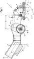
- the suction nozzle arrangement 1 shown consists of a connecting part 2, which is usually injection molded as a complex component made of plastic.
- a suction nozzle 3 is arranged in the front area of the connecting part 2 and is mounted in the connecting part 2 so as to be pivotable about a front horizontal transverse axis 5 via a first joint 4.
- the housing of the suction nozzle is not shown for reasons of clarity.
- the suction nozzle 3 has a slidable nozzle sole 6, which is guided directly over the floor surface when cleaning a resilient floor covering.
- the nozzle sole 6 is pierced by a transversely extending suction mouth 7, which is in flow connection with the vacuum source of the cylinder vacuum cleaner and picks up the dust from the floor.
- a circular arc to the rear Cantilever pipe bend 8 is provided, which is telescopically displaceable and sealed in a complementarily shaped flow channel of the connecting part 2.
- the curvature of the pipe bend 8 and the assigned area of the flow channel is carried out equidistant from the front transverse axis 5.
- the suction mouth 7 is delimited by an approximately vertical front wall 9 and an approximately vertical rear wall 10, which form a front suction edge 11 and a rear suction edge 12 in the transition to the nozzle sole 6.
- an imaginary straight line G 1 is drawn in a side view, which includes a front articulation angle ⁇ of 65 ° with a vertical V pointing downward from the transverse axis 5.
- a second joint 13 is provided, via which the connecting part 2 is rotatably connected to the intake manifold connector 14 about a rear horizontal transverse axis for connecting an intake manifold.
- rollers 15 are arranged on the connecting part 2, which can be rotated about a transverse, horizontal first axis of rotation 16 ′ and support the connecting part 2 in the rear region on the floor.
- the rollers 15 have a diameter D of 50 mm, so that the axis of rotation 16 'has a vertical distance H of 25 mm from the floor.
- the longitudinal axis G 2 of the intake manifold 14 includes with the vertical V a rear articulation angle ⁇ of 110 °.
- the selected cumulative articulation angle ⁇ of 175 ° has the effect that the flow of force from the intake manifold 14 in the direction of the suction mouth 7, in particular when moving in the forward direction, neither leads to the suction nozzle 3 digging into a flexible floor covering nor to an undesired lifting of the suction mouth 7, but instead the nozzle sole 6 in a with regard to the frictional force and dust absorption aligns favorable position relative to the ground.
- the front articulation angle ⁇ of 65 ° is particularly favorable with a view to gently deflecting the air flow into the flow duct and the associated avoidance of pneumatic power losses, which improves the dust pick-up with a given amount of suction air.
- sliding wheels 17 are mounted on the connecting part 2 so as to be rotatable about a second axis of rotation 18 which also runs transversely and horizontally. More precisely, the sliding wheels are mounted in the suction nozzle housing (not shown for reasons of clarity).
- the second axis of rotation 18 is arranged approximately centrally between the first axis of rotation 16 'and the transverse axis 5 such that the sliding wheels 17 are raised in the rest position by a distance h of 1.25 mm from the ground. When vacuuming hard floors, the sliding wheels 17 do not come into contact with the floor surface.
- the nozzle sole 6 penetrates into the floor covering due to the negative pressure. This leads to a lowering of the connecting part 2 and thus to a seating of the sliding wheels 17 on the floor surface. This counteracts a further tilting, which would cause a significant increase in resistance to movement.
- the horizontal distance A between the front and rear transverse axes is 84.5 mm in the exemplary embodiment.
Landscapes
- Engineering & Computer Science (AREA)
- Mechanical Engineering (AREA)
- Nozzles For Electric Vacuum Cleaners (AREA)
Claims (8)
- Agencement de buses d'aspiration (1) pour un aspirateur-traîneau, avec une buse d'aspiration (3) avec une bouche d'aspiration (7) présentant un bord d'aspiration avant et un bord d'aspiration arrière (11, 12), dans lequel la buse d'aspiration (3) est pivotante dans une pièce de liaison (2) selon une première articulation (4) autour d'un axe transversal horizontal avant (5), en outre avec une tubulure de tuyau d'aspiration (14) reliée de façon pivotante à la pièce de liaison (2) selon une deuxième articulation (13) avec un axe transversal horizontal arrière (16), ainsi qu'avec au moins un galet de roulement (15), logé en rotation autour d'un premier axe de rotation (16') sur la pièce de liaison (2) et en décalage vers l'arrière par rapport à la première articulation (4), et dans lequel l'axe longitudinal (G2) de la tubulure de tuyau d'aspiration (14) décrit avec une verticale (V) un angle d'articulation arrière (β) entre 105° et 115°, caractérisé en ce qu'une droite (G1) reliant le bord d'aspiration avant (11) de la bouche d'aspiration (7) et l'axe transversal avant (5) de la première articulation (4) décrit avec une verticale (V) s'étendant vers le bas à travers l'axe transversal avant (5) un angle d'articulation avant (α) entre 55° et 75°.
- Agencement de buses d'aspiration selon la revendication 1, caractérisé en ce que l'angle d'articulation avant (α) se situe entre 60° et 70°.
- Agencement de buses d'aspiration selon l'une des revendications 1 à 2, caractérisé en ce qu'une droite (G1) reliant le bord d'aspiration avant (11) de la bouche d'aspiration (7) et l'axe transversal avant (5) de la première articulation (4) décrit avec un axe longitudinal (G2) de la tubulure de tuyau d'aspiration (14) un angle d'articulation cumulé (χ) entre 170° et 180°, dans lequel l'angle d'articulation cumulé (χ) correspond à la somme de l'angle d'articulation avant (α) décrit par une droite (G1) reliant le bord d'aspiration avant (11) de la bouche d'aspiration (7) et l'axe transversal avant (5) de la première articulation (4) avec une verticale (V) s'étendant vers le bas à travers l'axe transversal avant (5), et d'un angle d'articulation arrière (β) décrit par l'axe longitudinal (G2) de la tubulure de tuyau d'aspiration (14) avec la verticale (V).
- Agencement de buses d'aspiration selon la revendication 3, caractérisé en ce que l'angle d'articulation cumulé (χ) se situe entre 173° et 177°.
- Agencement de buses d'aspiration selon l'une des revendications précédentes, caractérisé en ce que l'axe de rotation (16') du galet de roulement (15) et l'axe transversal arrière (16) de la deuxième articulation (13) se trouvent sur une verticale commune.
- Agencement de buses d'aspiration selon la revendication 5, caractérisé en ce que l'axe de rotation (16') du galet de roulement (15) coïncide avec l'axe transversal arrière (16) de la deuxième articulation (13).
- Agencement de buses d'aspiration selon l'une des revendications précédentes, caractérisé en ce que le diamètre (D) du galet de roulement (15) est inférieur à 75 mm, se situe en particulier entre 40 mm et 60 mm et atteint de façon particulièrement avantageuse approximativement 50 mm.
- Aspirateur-traîneau avec un agencement de buses d'aspiration selon l'une des revendications précédentes.
Applications Claiming Priority (1)
| Application Number | Priority Date | Filing Date | Title |
|---|---|---|---|
| DE102010043515.5A DE102010043515B4 (de) | 2010-11-05 | 2010-11-05 | Saugdüsenanordnung und Bodenstaubsauger |
Publications (3)
| Publication Number | Publication Date |
|---|---|
| EP2449934A2 EP2449934A2 (fr) | 2012-05-09 |
| EP2449934A3 EP2449934A3 (fr) | 2017-12-27 |
| EP2449934B1 true EP2449934B1 (fr) | 2020-01-01 |
Family
ID=45491232
Family Applications (1)
| Application Number | Title | Priority Date | Filing Date |
|---|---|---|---|
| EP11186312.2A Active EP2449934B1 (fr) | 2010-11-05 | 2011-10-24 | Agencement de buses d'aspiration pour un aspirateur de sol |
Country Status (2)
| Country | Link |
|---|---|
| EP (1) | EP2449934B1 (fr) |
| DE (1) | DE102010043515B4 (fr) |
Families Citing this family (10)
| Publication number | Priority date | Publication date | Assignee | Title |
|---|---|---|---|---|
| DE102012106570B4 (de) * | 2012-07-19 | 2014-08-28 | Wessel-Werk Gmbh | Staubsaugerdüse, insbesondere für Haushaltsstaubsauger |
| CN105142477B (zh) * | 2013-03-21 | 2017-07-04 | 伊莱克斯公司 | 具有铰接的刚性部件的真空吸尘器吸嘴 |
| DE102014107812A1 (de) * | 2014-06-03 | 2015-12-03 | Vorwerk & Co. Interholding Gmbh | Staubsaugerdüse für einen Staubsauger |
| ITUA20162159A1 (it) * | 2016-03-31 | 2017-10-01 | New Ermes Europe Srl | Testa di aspirazione con canale di aspirazione perfezionato |
| US11224319B2 (en) | 2017-12-11 | 2022-01-18 | New Ermes Europe S.R.L. | Base plate for a vacuum cleaner suction head for the suction of fine dust and large debris |
| DE102018122352A1 (de) * | 2018-09-13 | 2020-03-19 | Miele & Cie. Kg | Bodendüse mit einer Radanordnung, Staubsauger mit einer Bodendüse und Verfahren zur Herstellung einer Bodendüse |
| JP1641037S (fr) | 2018-09-18 | 2019-09-09 | ||
| IT202000001555A1 (it) | 2020-01-28 | 2021-07-28 | New Ermes Europe Srl | Dispositivo adattatore per aspirapolvere elettrico senza filo |
| USD953673S1 (en) | 2020-02-17 | 2022-05-31 | New Ermes Europe S.R.L. | Head of a vacuum cleaner |
| CN113349676B (zh) * | 2020-03-03 | 2024-05-28 | 苏州市春菊电器有限公司 | 一种具有灵活转轴结构的吸尘器地刷 |
Family Cites Families (15)
| Publication number | Priority date | Publication date | Assignee | Title |
|---|---|---|---|---|
| GB1493097A (en) * | 1976-07-09 | 1977-11-23 | Wessel H | Suction cleaner nozzles |
| DE3009648C2 (de) * | 1980-03-13 | 1983-03-17 | Hans 5226 Reichshof Wessel | Staubsaugerdüse mit einem Anschlußelement und einer Gleitsohle |
| DE3618803A1 (de) * | 1986-06-04 | 1987-12-10 | Vorwerk Co Interholding | Staubsaugermundstueck |
| DE8809802U1 (de) * | 1988-08-01 | 1989-11-30 | Siemens AG, 1000 Berlin und 8000 München | Staubsaugermundstück |
| DE8901995U1 (de) * | 1989-02-20 | 1990-06-28 | Siemens AG, 1000 Berlin und 8000 München | Einlegegelenk |
| DE29619645U1 (de) * | 1996-11-12 | 1997-01-23 | Wessel-Werk GmbH, 51580 Reichshof | Staubsauger mit Saugkopf und Bedienungsstange sowie Drehschwenkgelenk |
| DE29900713U1 (de) * | 1999-01-16 | 1999-06-24 | Wessel-Werk GmbH, 51580 Reichshof | Saugkopf für Bodenstaubsauger |
| US20080222839A1 (en) * | 2005-09-14 | 2008-09-18 | Koninklijke Philips Electronics N.V. | Suction Nozzle and Vacuum Cleaner Provided with Such a Suction Nozzle |
| KR100667885B1 (ko) * | 2005-09-27 | 2007-01-16 | 삼성광주전자 주식회사 | 진공청소기용 브러시 조립체 및 이를 구비한 진공청소기 |
| DE102006031486A1 (de) * | 2006-07-07 | 2008-01-10 | Wessel-Werk Gmbh | Düse für Bodenstaubsauger |
| DE102007009958B4 (de) * | 2007-03-01 | 2013-08-01 | Wessel-Werk Gmbh | Blechgleitsohle sowie Verfahren zu deren Auslegung |
| DE102007010517B4 (de) * | 2007-03-05 | 2013-04-11 | Wessel-Werk Gmbh | Düse für einen Bodenstaubsauger |
| DE102007057349B4 (de) * | 2007-11-28 | 2012-01-12 | Wessel-Werk Gmbh | Bodendüse für Staubsauger |
| DE102008012889B4 (de) * | 2008-03-06 | 2012-04-19 | Wessel-Werk Gmbh | Saugdüse für Bodenstaubsauger |
| DE202009010089U1 (de) * | 2009-06-18 | 2009-11-12 | Wessel-Werk Gmbh | Bodendüse für Staubsauger |
-
2010
- 2010-11-05 DE DE102010043515.5A patent/DE102010043515B4/de active Active
-
2011
- 2011-10-24 EP EP11186312.2A patent/EP2449934B1/fr active Active
Non-Patent Citations (1)
| Title |
|---|
| None * |
Also Published As
| Publication number | Publication date |
|---|---|
| DE102010043515A1 (de) | 2012-05-10 |
| EP2449934A3 (fr) | 2017-12-27 |
| DE102010043515B4 (de) | 2014-10-16 |
| EP2449934A2 (fr) | 2012-05-09 |
Similar Documents
| Publication | Publication Date | Title |
|---|---|---|
| EP2449934B1 (fr) | Agencement de buses d'aspiration pour un aspirateur de sol | |
| EP1875846B1 (fr) | Buse pour aspirateur de sol | |
| DE102012106571B4 (de) | Staubsaugerdüse, insbesondere für Haushaltsstaubsauger | |
| DE4304681C2 (de) | Einteilige Staubsaugerdüse | |
| EP2092869B1 (fr) | Buse pour aspirateur de sol | |
| EP2449935B1 (fr) | Buse d'aspiration et aspirateur de sol | |
| DE102012106570B4 (de) | Staubsaugerdüse, insbesondere für Haushaltsstaubsauger | |
| DE2846847A1 (de) | Bodenduese fuer staubsauger | |
| EP2338399B1 (fr) | Buse de sol pour aspirateur | |
| DE3009648C2 (de) | Staubsaugerdüse mit einem Anschlußelement und einer Gleitsohle | |
| EP1214902A2 (fr) | Buse pour aspirateur | |
| DE202011051495U1 (de) | Düse für Staubsauger mit innenliegendem Ansaugkanal | |
| EP3025626A1 (fr) | Buse de sol pour un appareil d'entretien du sol et procede de fabrication d'une buse de sol pour un appareil d'entretien du sol | |
| DE102009029806A1 (de) | Bodendüse für Staubsauger | |
| DE19738046A1 (de) | Statische Staubsaugerdüse, insbesondere für Haushaltsstaubsauger | |
| EP2233054B1 (fr) | Aspirateur doté d'un élément de liaison | |
| EP3042597B1 (fr) | Buse de sol pour aspirateur | |
| DE102012112532A1 (de) | Upright-Staubsauger | |
| WO2018036603A1 (fr) | Suceur pour un aspirateur, procédé d'aspiration de surfaces textiles et aspirateur | |
| DE102006060855B4 (de) | Bodendüse für Staubsauger | |
| EP1962660B1 (fr) | Buse de sol pour aspirateur | |
| DE8716492U1 (de) | Staubsaugermundstück mit einem kippbar angeordneten Mundstückkörper | |
| DE10144129A1 (de) | Düse für einen Staubsauger | |
| WO1999066823A1 (fr) | Embout d'aspirateur | |
| WO2005035135A2 (fr) | Bec pour systeme d'aspiration ou de soufflage |
Legal Events
| Date | Code | Title | Description |
|---|---|---|---|
| PUAI | Public reference made under article 153(3) epc to a published international application that has entered the european phase |
Free format text: ORIGINAL CODE: 0009012 |
|
| AK | Designated contracting states |
Kind code of ref document: A2 Designated state(s): AL AT BE BG CH CY CZ DE DK EE ES FI FR GB GR HR HU IE IS IT LI LT LU LV MC MK MT NL NO PL PT RO RS SE SI SK SM TR |
|
| AX | Request for extension of the european patent |
Extension state: BA ME |
|
| RAP1 | Party data changed (applicant data changed or rights of an application transferred) |
Owner name: BSH HAUSGERAETE GMBH |
|
| PUAL | Search report despatched |
Free format text: ORIGINAL CODE: 0009013 |
|
| AK | Designated contracting states |
Kind code of ref document: A3 Designated state(s): AL AT BE BG CH CY CZ DE DK EE ES FI FR GB GR HR HU IE IS IT LI LT LU LV MC MK MT NL NO PL PT RO RS SE SI SK SM TR |
|
| AX | Request for extension of the european patent |
Extension state: BA ME |
|
| RIC1 | Information provided on ipc code assigned before grant |
Ipc: A47L 9/02 20060101AFI20171117BHEP Ipc: A47L 5/36 20060101ALI20171117BHEP |
|
| STAA | Information on the status of an ep patent application or granted ep patent |
Free format text: STATUS: REQUEST FOR EXAMINATION WAS MADE |
|
| 17P | Request for examination filed |
Effective date: 20180627 |
|
| RBV | Designated contracting states (corrected) |
Designated state(s): AL AT BE BG CH CY CZ DE DK EE ES FI FR GB GR HR HU IE IS IT LI LT LU LV MC MK MT NL NO PL PT RO RS SE SI SK SM TR |
|
| GRAP | Despatch of communication of intention to grant a patent |
Free format text: ORIGINAL CODE: EPIDOSNIGR1 |
|
| STAA | Information on the status of an ep patent application or granted ep patent |
Free format text: STATUS: GRANT OF PATENT IS INTENDED |
|
| INTG | Intention to grant announced |
Effective date: 20190830 |
|
| GRAS | Grant fee paid |
Free format text: ORIGINAL CODE: EPIDOSNIGR3 |
|
| GRAA | (expected) grant |
Free format text: ORIGINAL CODE: 0009210 |
|
| STAA | Information on the status of an ep patent application or granted ep patent |
Free format text: STATUS: THE PATENT HAS BEEN GRANTED |
|
| AK | Designated contracting states |
Kind code of ref document: B1 Designated state(s): AL AT BE BG CH CY CZ DE DK EE ES FI FR GB GR HR HU IE IS IT LI LT LU LV MC MK MT NL NO PL PT RO RS SE SI SK SM TR |
|
| REG | Reference to a national code |
Ref country code: GB Ref legal event code: FG4D Free format text: NOT ENGLISH |
|
| REG | Reference to a national code |
Ref country code: CH Ref legal event code: EP Ref country code: AT Ref legal event code: REF Ref document number: 1218732 Country of ref document: AT Kind code of ref document: T Effective date: 20200115 |
|
| REG | Reference to a national code |
Ref country code: DE Ref legal event code: R096 Ref document number: 502011016358 Country of ref document: DE |
|
| REG | Reference to a national code |
Ref country code: IE Ref legal event code: FG4D Free format text: LANGUAGE OF EP DOCUMENT: GERMAN |
|
| REG | Reference to a national code |
Ref country code: NL Ref legal event code: MP Effective date: 20200101 |
|
| REG | Reference to a national code |
Ref country code: LT Ref legal event code: MG4D |
|
| PG25 | Lapsed in a contracting state [announced via postgrant information from national office to epo] |
Ref country code: CZ Free format text: LAPSE BECAUSE OF FAILURE TO SUBMIT A TRANSLATION OF THE DESCRIPTION OR TO PAY THE FEE WITHIN THE PRESCRIBED TIME-LIMIT Effective date: 20200101 Ref country code: PT Free format text: LAPSE BECAUSE OF FAILURE TO SUBMIT A TRANSLATION OF THE DESCRIPTION OR TO PAY THE FEE WITHIN THE PRESCRIBED TIME-LIMIT Effective date: 20200527 Ref country code: FI Free format text: LAPSE BECAUSE OF FAILURE TO SUBMIT A TRANSLATION OF THE DESCRIPTION OR TO PAY THE FEE WITHIN THE PRESCRIBED TIME-LIMIT Effective date: 20200101 Ref country code: NL Free format text: LAPSE BECAUSE OF FAILURE TO SUBMIT A TRANSLATION OF THE DESCRIPTION OR TO PAY THE FEE WITHIN THE PRESCRIBED TIME-LIMIT Effective date: 20200101 Ref country code: RS Free format text: LAPSE BECAUSE OF FAILURE TO SUBMIT A TRANSLATION OF THE DESCRIPTION OR TO PAY THE FEE WITHIN THE PRESCRIBED TIME-LIMIT Effective date: 20200101 Ref country code: LT Free format text: LAPSE BECAUSE OF FAILURE TO SUBMIT A TRANSLATION OF THE DESCRIPTION OR TO PAY THE FEE WITHIN THE PRESCRIBED TIME-LIMIT Effective date: 20200101 Ref country code: NO Free format text: LAPSE BECAUSE OF FAILURE TO SUBMIT A TRANSLATION OF THE DESCRIPTION OR TO PAY THE FEE WITHIN THE PRESCRIBED TIME-LIMIT Effective date: 20200401 |
|
| PG25 | Lapsed in a contracting state [announced via postgrant information from national office to epo] |
Ref country code: BG Free format text: LAPSE BECAUSE OF FAILURE TO SUBMIT A TRANSLATION OF THE DESCRIPTION OR TO PAY THE FEE WITHIN THE PRESCRIBED TIME-LIMIT Effective date: 20200401 Ref country code: IS Free format text: LAPSE BECAUSE OF FAILURE TO SUBMIT A TRANSLATION OF THE DESCRIPTION OR TO PAY THE FEE WITHIN THE PRESCRIBED TIME-LIMIT Effective date: 20200501 Ref country code: SE Free format text: LAPSE BECAUSE OF FAILURE TO SUBMIT A TRANSLATION OF THE DESCRIPTION OR TO PAY THE FEE WITHIN THE PRESCRIBED TIME-LIMIT Effective date: 20200101 Ref country code: LV Free format text: LAPSE BECAUSE OF FAILURE TO SUBMIT A TRANSLATION OF THE DESCRIPTION OR TO PAY THE FEE WITHIN THE PRESCRIBED TIME-LIMIT Effective date: 20200101 Ref country code: GR Free format text: LAPSE BECAUSE OF FAILURE TO SUBMIT A TRANSLATION OF THE DESCRIPTION OR TO PAY THE FEE WITHIN THE PRESCRIBED TIME-LIMIT Effective date: 20200402 Ref country code: HR Free format text: LAPSE BECAUSE OF FAILURE TO SUBMIT A TRANSLATION OF THE DESCRIPTION OR TO PAY THE FEE WITHIN THE PRESCRIBED TIME-LIMIT Effective date: 20200101 |
|
| REG | Reference to a national code |
Ref country code: DE Ref legal event code: R097 Ref document number: 502011016358 Country of ref document: DE |
|
| PG25 | Lapsed in a contracting state [announced via postgrant information from national office to epo] |
Ref country code: ES Free format text: LAPSE BECAUSE OF FAILURE TO SUBMIT A TRANSLATION OF THE DESCRIPTION OR TO PAY THE FEE WITHIN THE PRESCRIBED TIME-LIMIT Effective date: 20200101 Ref country code: DK Free format text: LAPSE BECAUSE OF FAILURE TO SUBMIT A TRANSLATION OF THE DESCRIPTION OR TO PAY THE FEE WITHIN THE PRESCRIBED TIME-LIMIT Effective date: 20200101 Ref country code: SK Free format text: LAPSE BECAUSE OF FAILURE TO SUBMIT A TRANSLATION OF THE DESCRIPTION OR TO PAY THE FEE WITHIN THE PRESCRIBED TIME-LIMIT Effective date: 20200101 Ref country code: EE Free format text: LAPSE BECAUSE OF FAILURE TO SUBMIT A TRANSLATION OF THE DESCRIPTION OR TO PAY THE FEE WITHIN THE PRESCRIBED TIME-LIMIT Effective date: 20200101 Ref country code: SM Free format text: LAPSE BECAUSE OF FAILURE TO SUBMIT A TRANSLATION OF THE DESCRIPTION OR TO PAY THE FEE WITHIN THE PRESCRIBED TIME-LIMIT Effective date: 20200101 Ref country code: RO Free format text: LAPSE BECAUSE OF FAILURE TO SUBMIT A TRANSLATION OF THE DESCRIPTION OR TO PAY THE FEE WITHIN THE PRESCRIBED TIME-LIMIT Effective date: 20200101 |
|
| PLBE | No opposition filed within time limit |
Free format text: ORIGINAL CODE: 0009261 |
|
| STAA | Information on the status of an ep patent application or granted ep patent |
Free format text: STATUS: NO OPPOSITION FILED WITHIN TIME LIMIT |
|
| 26N | No opposition filed |
Effective date: 20201002 |
|
| PG25 | Lapsed in a contracting state [announced via postgrant information from national office to epo] |
Ref country code: IT Free format text: LAPSE BECAUSE OF FAILURE TO SUBMIT A TRANSLATION OF THE DESCRIPTION OR TO PAY THE FEE WITHIN THE PRESCRIBED TIME-LIMIT Effective date: 20200101 |
|
| PG25 | Lapsed in a contracting state [announced via postgrant information from national office to epo] |
Ref country code: SI Free format text: LAPSE BECAUSE OF FAILURE TO SUBMIT A TRANSLATION OF THE DESCRIPTION OR TO PAY THE FEE WITHIN THE PRESCRIBED TIME-LIMIT Effective date: 20200101 Ref country code: PL Free format text: LAPSE BECAUSE OF FAILURE TO SUBMIT A TRANSLATION OF THE DESCRIPTION OR TO PAY THE FEE WITHIN THE PRESCRIBED TIME-LIMIT Effective date: 20200101 |
|
| REG | Reference to a national code |
Ref country code: CH Ref legal event code: PL |
|
| GBPC | Gb: european patent ceased through non-payment of renewal fee |
Effective date: 20201024 |
|
| PG25 | Lapsed in a contracting state [announced via postgrant information from national office to epo] |
Ref country code: LU Free format text: LAPSE BECAUSE OF NON-PAYMENT OF DUE FEES Effective date: 20201024 Ref country code: MC Free format text: LAPSE BECAUSE OF FAILURE TO SUBMIT A TRANSLATION OF THE DESCRIPTION OR TO PAY THE FEE WITHIN THE PRESCRIBED TIME-LIMIT Effective date: 20200101 |
|
| REG | Reference to a national code |
Ref country code: BE Ref legal event code: MM Effective date: 20201031 |
|
| PG25 | Lapsed in a contracting state [announced via postgrant information from national office to epo] |
Ref country code: FR Free format text: LAPSE BECAUSE OF NON-PAYMENT OF DUE FEES Effective date: 20201031 |
|
| PG25 | Lapsed in a contracting state [announced via postgrant information from national office to epo] |
Ref country code: CH Free format text: LAPSE BECAUSE OF NON-PAYMENT OF DUE FEES Effective date: 20201031 Ref country code: BE Free format text: LAPSE BECAUSE OF NON-PAYMENT OF DUE FEES Effective date: 20201031 Ref country code: LI Free format text: LAPSE BECAUSE OF NON-PAYMENT OF DUE FEES Effective date: 20201031 Ref country code: GB Free format text: LAPSE BECAUSE OF NON-PAYMENT OF DUE FEES Effective date: 20201024 |
|
| PG25 | Lapsed in a contracting state [announced via postgrant information from national office to epo] |
Ref country code: IE Free format text: LAPSE BECAUSE OF NON-PAYMENT OF DUE FEES Effective date: 20201024 |
|
| REG | Reference to a national code |
Ref country code: AT Ref legal event code: MM01 Ref document number: 1218732 Country of ref document: AT Kind code of ref document: T Effective date: 20201024 |
|
| PG25 | Lapsed in a contracting state [announced via postgrant information from national office to epo] |
Ref country code: AT Free format text: LAPSE BECAUSE OF NON-PAYMENT OF DUE FEES Effective date: 20201024 |
|
| PG25 | Lapsed in a contracting state [announced via postgrant information from national office to epo] |
Ref country code: TR Free format text: LAPSE BECAUSE OF FAILURE TO SUBMIT A TRANSLATION OF THE DESCRIPTION OR TO PAY THE FEE WITHIN THE PRESCRIBED TIME-LIMIT Effective date: 20200101 Ref country code: MT Free format text: LAPSE BECAUSE OF FAILURE TO SUBMIT A TRANSLATION OF THE DESCRIPTION OR TO PAY THE FEE WITHIN THE PRESCRIBED TIME-LIMIT Effective date: 20200101 Ref country code: CY Free format text: LAPSE BECAUSE OF FAILURE TO SUBMIT A TRANSLATION OF THE DESCRIPTION OR TO PAY THE FEE WITHIN THE PRESCRIBED TIME-LIMIT Effective date: 20200101 |
|
| PG25 | Lapsed in a contracting state [announced via postgrant information from national office to epo] |
Ref country code: MK Free format text: LAPSE BECAUSE OF FAILURE TO SUBMIT A TRANSLATION OF THE DESCRIPTION OR TO PAY THE FEE WITHIN THE PRESCRIBED TIME-LIMIT Effective date: 20200101 Ref country code: AL Free format text: LAPSE BECAUSE OF FAILURE TO SUBMIT A TRANSLATION OF THE DESCRIPTION OR TO PAY THE FEE WITHIN THE PRESCRIBED TIME-LIMIT Effective date: 20200101 |
|
| P01 | Opt-out of the competence of the unified patent court (upc) registered |
Effective date: 20230504 |
|
| PGFP | Annual fee paid to national office [announced via postgrant information from national office to epo] |
Ref country code: DE Payment date: 20251031 Year of fee payment: 15 |