EP2450125A2 - Configurations de machine de système de moulage - Google Patents
Configurations de machine de système de moulage Download PDFInfo
- Publication number
- EP2450125A2 EP2450125A2 EP11187864A EP11187864A EP2450125A2 EP 2450125 A2 EP2450125 A2 EP 2450125A2 EP 11187864 A EP11187864 A EP 11187864A EP 11187864 A EP11187864 A EP 11187864A EP 2450125 A2 EP2450125 A2 EP 2450125A2
- Authority
- EP
- European Patent Office
- Prior art keywords
- shot tube
- die
- die casting
- recited
- casting system
- Prior art date
- Legal status (The legal status is an assumption and is not a legal conclusion. Google has not performed a legal analysis and makes no representation as to the accuracy of the status listed.)
- Granted
Links
- 238000004512 die casting Methods 0.000 title claims abstract description 78
- 239000000463 material Substances 0.000 claims abstract description 43
- 238000002844 melting Methods 0.000 claims abstract description 32
- 230000008018 melting Effects 0.000 claims abstract description 32
- 238000004891 communication Methods 0.000 claims abstract description 8
- 239000012530 fluid Substances 0.000 claims abstract description 8
- 229910052751 metal Inorganic materials 0.000 claims description 37
- 239000002184 metal Substances 0.000 claims description 37
- 238000000034 method Methods 0.000 claims description 14
- 230000006698 induction Effects 0.000 claims description 10
- RYGMFSIKBFXOCR-UHFFFAOYSA-N Copper Chemical compound [Cu] RYGMFSIKBFXOCR-UHFFFAOYSA-N 0.000 claims description 6
- 238000002347 injection Methods 0.000 claims description 6
- 239000007924 injection Substances 0.000 claims description 6
- 238000010438 heat treatment Methods 0.000 claims description 4
- 238000000829 induction skull melting Methods 0.000 claims description 4
- OKTJSMMVPCPJKN-UHFFFAOYSA-N Carbon Chemical compound [C] OKTJSMMVPCPJKN-UHFFFAOYSA-N 0.000 claims description 3
- 239000000919 ceramic Substances 0.000 claims description 3
- 229910002804 graphite Inorganic materials 0.000 claims description 3
- 239000010439 graphite Substances 0.000 claims description 3
- 239000007787 solid Substances 0.000 claims description 3
- 230000007246 mechanism Effects 0.000 description 9
- 238000005266 casting Methods 0.000 description 7
- 239000002826 coolant Substances 0.000 description 6
- XKRFYHLGVUSROY-UHFFFAOYSA-N Argon Chemical compound [Ar] XKRFYHLGVUSROY-UHFFFAOYSA-N 0.000 description 4
- 229910052802 copper Inorganic materials 0.000 description 4
- 239000010949 copper Substances 0.000 description 4
- 230000008569 process Effects 0.000 description 4
- 210000003625 skull Anatomy 0.000 description 4
- 229910045601 alloy Inorganic materials 0.000 description 3
- 239000000956 alloy Substances 0.000 description 3
- 238000001816 cooling Methods 0.000 description 3
- 238000005495 investment casting Methods 0.000 description 3
- PXHVJJICTQNCMI-UHFFFAOYSA-N Nickel Chemical compound [Ni] PXHVJJICTQNCMI-UHFFFAOYSA-N 0.000 description 2
- 229910052786 argon Inorganic materials 0.000 description 2
- 229910010293 ceramic material Inorganic materials 0.000 description 2
- 238000011109 contamination Methods 0.000 description 2
- 239000011261 inert gas Substances 0.000 description 2
- 238000012986 modification Methods 0.000 description 2
- 230000004048 modification Effects 0.000 description 2
- XLYOFNOQVPJJNP-UHFFFAOYSA-N water Substances O XLYOFNOQVPJJNP-UHFFFAOYSA-N 0.000 description 2
- 229910000838 Al alloy Inorganic materials 0.000 description 1
- 229910000640 Fe alloy Inorganic materials 0.000 description 1
- ZOKXTWBITQBERF-UHFFFAOYSA-N Molybdenum Chemical compound [Mo] ZOKXTWBITQBERF-UHFFFAOYSA-N 0.000 description 1
- 229910001069 Ti alloy Inorganic materials 0.000 description 1
- QVGXLLKOCUKJST-UHFFFAOYSA-N atomic oxygen Chemical compound [O] QVGXLLKOCUKJST-UHFFFAOYSA-N 0.000 description 1
- 230000015572 biosynthetic process Effects 0.000 description 1
- 230000007547 defect Effects 0.000 description 1
- 238000013461 design Methods 0.000 description 1
- 239000007789 gas Substances 0.000 description 1
- 238000004519 manufacturing process Methods 0.000 description 1
- 239000012768 molten material Substances 0.000 description 1
- 229910052750 molybdenum Inorganic materials 0.000 description 1
- 239000011733 molybdenum Substances 0.000 description 1
- 229910052759 nickel Inorganic materials 0.000 description 1
- 229910052758 niobium Inorganic materials 0.000 description 1
- 239000010955 niobium Substances 0.000 description 1
- GUCVJGMIXFAOAE-UHFFFAOYSA-N niobium atom Chemical compound [Nb] GUCVJGMIXFAOAE-UHFFFAOYSA-N 0.000 description 1
- 239000001301 oxygen Substances 0.000 description 1
- 229910052760 oxygen Inorganic materials 0.000 description 1
- 238000012856 packing Methods 0.000 description 1
- 230000009467 reduction Effects 0.000 description 1
- 239000003870 refractory metal Substances 0.000 description 1
- 229910000601 superalloy Inorganic materials 0.000 description 1
- 230000008646 thermal stress Effects 0.000 description 1
- 238000012546 transfer Methods 0.000 description 1
- WFKWXMTUELFFGS-UHFFFAOYSA-N tungsten Chemical compound [W] WFKWXMTUELFFGS-UHFFFAOYSA-N 0.000 description 1
- 229910052721 tungsten Inorganic materials 0.000 description 1
- 239000010937 tungsten Substances 0.000 description 1
Images

Classifications
-
- B—PERFORMING OPERATIONS; TRANSPORTING
- B22—CASTING; POWDER METALLURGY
- B22D—CASTING OF METALS; CASTING OF OTHER SUBSTANCES BY THE SAME PROCESSES OR DEVICES
- B22D17/00—Pressure die casting or injection die casting, i.e. casting in which the metal is forced into a mould under high pressure
- B22D17/02—Hot chamber machines, i.e. with heated press chamber in which metal is melted
- B22D17/04—Plunger machines
-
- B—PERFORMING OPERATIONS; TRANSPORTING
- B22—CASTING; POWDER METALLURGY
- B22D—CASTING OF METALS; CASTING OF OTHER SUBSTANCES BY THE SAME PROCESSES OR DEVICES
- B22D17/00—Pressure die casting or injection die casting, i.e. casting in which the metal is forced into a mould under high pressure
- B22D17/20—Accessories: Details
- B22D17/2015—Means for forcing the molten metal into the die
- B22D17/2038—Heating, cooling or lubricating the injection unit
-
- B—PERFORMING OPERATIONS; TRANSPORTING
- B22—CASTING; POWDER METALLURGY
- B22D—CASTING OF METALS; CASTING OF OTHER SUBSTANCES BY THE SAME PROCESSES OR DEVICES
- B22D17/00—Pressure die casting or injection die casting, i.e. casting in which the metal is forced into a mould under high pressure
- B22D17/08—Cold chamber machines, i.e. with unheated press chamber into which molten metal is ladled
- B22D17/10—Cold chamber machines, i.e. with unheated press chamber into which molten metal is ladled with horizontal press motion
-
- B—PERFORMING OPERATIONS; TRANSPORTING
- B22—CASTING; POWDER METALLURGY
- B22D—CASTING OF METALS; CASTING OF OTHER SUBSTANCES BY THE SAME PROCESSES OR DEVICES
- B22D17/00—Pressure die casting or injection die casting, i.e. casting in which the metal is forced into a mould under high pressure
- B22D17/14—Machines with evacuated die cavity
-
- B—PERFORMING OPERATIONS; TRANSPORTING
- B22—CASTING; POWDER METALLURGY
- B22D—CASTING OF METALS; CASTING OF OTHER SUBSTANCES BY THE SAME PROCESSES OR DEVICES
- B22D17/00—Pressure die casting or injection die casting, i.e. casting in which the metal is forced into a mould under high pressure
- B22D17/20—Accessories: Details
- B22D17/2015—Means for forcing the molten metal into the die
- B22D17/2023—Nozzles or shot sleeves
-
- B—PERFORMING OPERATIONS; TRANSPORTING
- B22—CASTING; POWDER METALLURGY
- B22D—CASTING OF METALS; CASTING OF OTHER SUBSTANCES BY THE SAME PROCESSES OR DEVICES
- B22D17/00—Pressure die casting or injection die casting, i.e. casting in which the metal is forced into a mould under high pressure
- B22D17/20—Accessories: Details
- B22D17/30—Accessories for supplying molten metal, e.g. in rations
Definitions
- This disclosure relates generally to casting, and more particularly to die casting system machine configurations.
- Casting is a known technique used to yield substantially net-shaped components.
- investment casting is often used in the gas turbine engine industry to manufacture net-shaped components, such as blades and vanes having relatively complex shapes.
- Investment casting involves pouring molten metal into a ceramic shell having a cavity in the shape of the component to be cast.
- Investment casting can be relatively labor intensive, time consuming and expensive.
- Die casting involves injecting molten metal directly into a reusable die to yield a net-shaped component. Die casting has typically been used to produce components that do not require high thermal mechanical performance. For example, die casting is commonly used to produce components made from relatively low melting temperature materials that are not exposed to extreme temperatures. Existing machine configurations for die casting systems have not been effective to cast components made from high temperature alloys.
- a die casting system includes a die, a shot tube and a shot tube plunger.
- the die is comprised of a plurality of die components that define a die cavity.
- the shot tube is in fluid communication with the die cavity and includes an integrated melting unit configured to heat a charge of material from a position inside the shot tube.
- the shot tube plunger is moveable within the shot tube to communicate the charge of material into the die cavity.
- a method of die casting a component includes loading a charge of material into a shot tube of a die casting system, heating the charge of material at a position inside the shot tube, and injecting the charge of material into a die cavity of the die casting system to form the component.
- a die casting system also disclosed includes a die, a shot tube and a shot tube plunger.
- the die is comprised of a plurality of die components that define a die cavity.
- the shot tube is in fluid communication with the die cavity.
- the shot tube plunger is moveable within the shot tube to communicate molten metal into the die cavity.
- the die casting system is positioned relative to a surface. Each of the die, the shot tube and the shot tube plunger are positioned at an angle relative to the surface during injection of the molten metal into the die cavity.
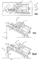
- Figure 1 illustrates a die casting system 10 having a machine configuration 11.
- the die casting system 10 includes a horizontal machine configuration.
- the die casting system 10 includes a reusable die 12 having a plurality of die elements 14, 16 that function to cast a component 15.
- two die elements 14, 16 are depicted in Figure 1 , it should be understood that the die 12 could include more or fewer die elements, as well as other parts and configurations.
- the die 12 is assembled by positioning the die elements 14, 16 together and holding the die elements 14, 16 at a desired positioning via a mechanism 18.
- the mechanism 18 could include a clamping mechanism of appropriate hydraulic, pneumatic, electromechanical and/or other configurations.
- the mechanism 18 also separates the die elements 14, 16 subsequent to casting.
- the die elements 14, 16 define internal surfaces that cooperate to define a die cavity 20.
- a shot tube 24 is in fluid communication with the die cavity 20 via one or more ports 26 located in the die element 14, the die element 16, or both.
- a shot tube plunger 28 is received within the shot tube 24 and is moveable between a retracted and injected position (in the direction of Arrow A) within the shot tube 24 by a mechanism 30.
- the mechanism 30 could include a hydraulic assembly or other suitable mechanism, including, but not limited to, pneumatic, electromechanical or any combination thereof.
- the shot tube 24 receives a molten metal from a melting unit 25, such as a crucible, for forming the component 15.
- a melting unit 25 such as a crucible
- the molten metal is melted in the melting unit 25 at a location that is separate from the shot tube 24.
- this disclosure is not limited to melting units located separate from the other die casting system components.
- Materials capable of being used to diecast a component 15 include, but are not limited to, nickel based super alloys, titanium alloys, high temperature aluminum alloys, copper based alloys, iron alloys, molybdenum, tungsten, niobium or other refractory metals. This disclosure is not limited to the disclosed alloys, and it should be understood that any high melting temperature material may be utilized to cast the component 15. As used herein, the term "high melting temperature material" is intended to include materials having a melting temperature of approximately 1500°F (815°C) and higher.
- the shot tube 24 receives a sufficient amount of molten material to fill the die cavity 20.
- the shot tube plunger 28 is actuated to inject the molten metal under pressure from the shot tube 24 into the die cavity 20 to cast the component 15.
- the die casting system could be configured to cast multiple components in a single shot (see Figures 3 and 4 , for example).
- the die casting system 10 can be positioned within a vacuum chamber 34 that includes a vacuum source 35.
- a vacuum is applied in the vacuum chamber 34 via the vacuum source 35 to render a vacuum die casting process.
- the vacuum chamber 34 provides a non-reactive environment for the die casting system 10 that reduces reaction, contamination, or other conditions that could detrimentally affect the quality of the cast component 15, such as excess porosity of the die cast component that can occur as a result of exposure to oxygen.
- the vacuum chamber 34 is maintained at a pressure between 1 ⁇ 10 -3 Torr and 1x10 -4 Torr, although other pressures are contemplated.
- the actual pressure of the vacuum chamber 34 will vary based on the type of component 15 being cast, among other conditions and factors.
- the melting unit 25, the shot tube 24, and the die 12 are positioned within the vacuum chamber 34 during the die casting process such that the melting, injecting and solidifying of the metal are each performed under vacuum.
- the vacuum chamber 34 is backfilled with an inert gas, such as Argon, for example.
- the machine configuration 11 of the die casting system 10 depicted in Figure 1 is illustrative only and could include more or less sections, parts and/or components. This disclosure extends to all forms of die casting, including but not limited to, horizontal systems, vertical systems, vacuum systems, or non-vacuum systems. Described below are additional machine configurations of die casting systems capable of casting components made from high melting temperature materials.
- the example machine configurations described below and depicted in Figures 2-5 maintain thermal control of the molten metal received by the die casting system components and thereby minimize thermal losses (i.e., heat of the molten metal) during injection.
- the example machine configurations extend part life and reduce the defects caused by transfer of the molten metal from a location separate from the die casting system components.
- Figure 2 illustrates an example machine configuration 111 of a die casting system 110.
- like reference numerals signify like features
- reference numerals identified in multiples of 100 signify slightly modified features.
- selected features of one example embodiment may be combined with selected features of other example embodiments and still fall within the scope of this disclosure.
- the die casting system 110 is positioned relative to a surface 40, such as a machine shop floor, for example.
- the surface 40 is substantially flat.
- the die casting system 110 is substantially similar to the die casting system 10 of Figure 1 , except that the die casting system 110 is positioned at an angle ⁇ relative to the surface 40. That is, the machine configuration 111 includes an inclined positioning of the die casting system 110 relative to the surface 40.
- the die 12, the shot tube 24 and the shot tube plunger 28 are each angled relative to the surface 40 at an angle ⁇ .
- the machine configuration 111 therefore changes the orientation of the die casting system 110 relative to the surface 40 such that the surface area contact between molten metal and the interior of the shot tube 24 is reduced. Reduction of the surface area contact of the molten metal with the shot tube 24 minimizes thermal losses of the molten metal that can occur during injection, and reduces the thermal stresses acting upon the shot tube 24.
- the die casting system 110 is angled relative to the surface 40 at an angle of about 5° to about 85°. In another example, the die casting system 110 is angled relative to the surface 40 at an angle of about 30° to about 45°.
- the term "about” is intended to include the defined ranges and any slight modifications thereof, such as within a range of accepted tolerances.
- the die casting system 110 could be permanently inclined relative to the surface 40, such as by mounting the die casting system 110 to an inclined surface 41.
- the die casting system 110 includes a positioning system 42 that selectively inclines the die casting system 110 relative to the surface 40.
- the positioning system 42 includes cylinders 44 that are selectively actuable to position the die casting system 110 at a desired angle ⁇ relative to the surface 40.
- the positioning system 42 could include any appropriate hydraulic, pneumatic, electromechanical and/or other configurations for positioning the components of the die casting system 110 at a desired inclined angle ⁇ .
- the die casting system 110 could be positioned within a vacuum chamber powered by a vacuum source to render a vacuum die casting system, or a die casting system 110 could be positioned within a chamber that is backfilled with an inert gas, such as Argon, for example.
- an inert gas such as Argon
- Figure 3 illustrates another example machine configuration 211 for a die casting system 210.
- the machine configuration 211 of the die casting system 210 includes a vertical, bottom feed configuration.
- a vertical, bottom feed configuration is depicted, the advantages of this disclosure are applicable to other configurations including, but not limited to, horizontal, side feed and top feed configurations.
- the die casting system 210 includes a die 212 having a plurality of die elements 214, 216 that define a die cavity 220.
- a shot tube 224 is in fluid communication with the die cavity 220.
- a gate 221 connects the shot tube 224 to the die cavity 220.
- a shot tube plunger 228 is received within the shot tube 224 and is moveable between a retracted and injected position (in the direction of arrow A) within the shot tube 224 by a mechanism 230.
- the shot tube 224 includes an integrated melting unit 225 configured to heat a charge of material 237 from an interior position IP of the shot tube 224.
- the integrated melting unit 225 includes an induction coil 227 mounted about the shot tube 224.
- the induction coil 227 of the integrated melting unit 225 induces a current within the shot tube 224 to melt and/or superheat the charge of material 237 within the interior position IP of the shot tube 224. That is, the charge of material 237 can be either melted from inside of the shot tube 224, or can be melted separate from the shot tube 224 (such as in a crucible) and then transferred to the shot tube 224 and heated to a desired temperature inside of the shot tube 224.
- the induction coil 227 is powered by a power source 229 in a known manner.
- the example shot tube 224 can include a first sleeve 231 and a second sleeve 233.
- the first sleeve 231 is a graphite sleeve and the second sleeve 233 is a ceramic sleeve.
- the induction coil 227 is positioned around the second sleeve 233 to melt and/or heat a charge of material 237 (such as an ingot of a high melting temperature material) within the second sleeve 233.
- the charge of material 237 is transformed into molten metal and/or superheated once induced by the induction coil 227.
- the shot tube plunger 228 packs the molten metal into the first sleeve 231 of the shot tube 224.
- the first sleeve 231 is capable of withstanding the pressure of the packed molten metal.
- the sleeves 231, 233 are not limited to graphite and ceramic materials.
- the first sleeve 231 could also be comprised of metallic or ceramic materials, while the second sleeve 233 could include other materials.
- the actual materials utilized for the first sleeve 231 and the second sleeve 233 will vary depending upon design specific parameters, including but not limited to, the melting temperature of the charge of material 237 and the packing pressures created during injection of the shot tube plunger 228.
- FIG. 3B depicts example features of the shot tube plunger 228.
- the shot tube plunger 228 could include a cooled copper plunger 250.
- the cooled copper plunger 250 includes cooling channels 251 that receive a coolant 253, such as water, from a coolant source 255.
- the coolant 253 is circulated through the coolant channels 251 to remove heat from the shot tube plunger 228 as a result of direct contact with the molten metal during injection.
- the die casting system 210 could be positioned within a vacuum chamber 234 that includes a vacuum source 235.
- a vacuum is applied in the vacuum chamber 234 via the vacuum source 235 to render a vacuum die casting process.
- each of the shot tube 224, the integrated melting unit 225 and the die 212 are positioned within the vacuum chamber 234 during the die casting process such that the melting, injecting and solidifying of the metal are all performed under vacuum.
- a vacuum chamber 234 is depicted in Figure 3
- the die casting system 210 may also be utilized in non-vacuumed environments.
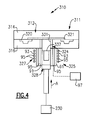
- Figure 4 illustrates yet another example machine configuration 311 associated with a die casting machine 310.
- the die casting system 310 is substantially similar to the die casting system 210 of Figure 3 .
- the example die casting system 310 includes a slightly modified integrated melting unit 325.
- the integrated melting unit 325 includes an induction skull melting system 327. That is, in this example machine configuration 311, the induction skull melting system 327 replaces the induction coil 227 depicted in Figure 3 .
- the die casting system 310 also includes a die 312 having a plurality of die elements 314, 316 that define a die cavity 320.
- a shot tube 324 is in fluid communication with the die cavity 320.
- a gate 321 connects the shot tube 324 to the die cavity 320.
- a shot tube plunger 328 is received within the shot tube 324 and is moveable between a retracted and injected position (in the direction of arrow A) within the shot tube 324 by a mechanism 230.
- the die casting system 310 could be positioned within a vacuum chamber powered by a vacuum source to render a vacuum die casting system.
- the induction skull melting system 327 of the integrated melting unit 325 includes wall segments 91 which are surrounded by an induction coil 93.
- the wall segments 91 are copper wall segments.
- the wall segments 91 and the induction coil 93 include cooling chambers 95 that receive a coolant, such as water, from a coolant source 97 to cool the wall segments 91 during contact with molten metal.
- a magnetic field is induced by the induction coil 93 and passes through the wall segments 91 to heat and melt the charge of material 337 to form molten metal.
- the shot tube plunger 328 is moveable to pack the molten metal within a sleeve 331 of the shot tube 324 to prepare the molten metal to be injected into the die cavity 320.
- the shot tube plunger 328 is a copper shot tube plunger and could include cooling channels (similar to those depicted by Figure 3B ) to cool the shot tube plunger 328 during contact with the molten metal.
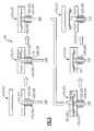
- Figure 5 schematically illustrates an example implementation 100 of the machine configurations 211, 311 of Figure 3 and Figure 4 .
- the example implementation 100 schematically depicts a method of die casting a component 15.
- the component 15 could include an aeronautical component, such as an airfoil or vane, for example.
- an aeronautical component such as an airfoil or vane, for example.
- the casting of non-aeronautical components is also contemplated as within the scope of this disclosure.
- the example implementation 100 includes loading a charge of material 237, 337 within a shot tube 224, 324 of a die casting system 210, 310, which is depicted at step block 102.
- the charge of material 237, 337 is molten metal that is melted in a melting unit 25 (See Figure 1 ) separate from the die casting systems 210, 310 and poured into the shot tube 224, 324.
- the charge of material 237, 337 is a solid ingot of material that is positioned inside the shot tube 224, 324 prior to melting.
- the charge of material 237, 337 is a high melting temperature material.
- the charge of material 237, 337 is heated from a position inside of the shot tube 224, 324.
- the charge of material 237, 337 is heated with an integrated melting unit 225, 325.
- a skull 75 forms on an interface defined between the shot tube plunger 228, 328 and the molten metal to seal the shot tube 224, 324.
- the molten metal is advanced through the integrated melting unit 225, 325 at step block 106.
- the shot tube plunger 228, 328 pushes on the skull 75 formed at step block 104. Formation and advancement of the skull 75 protects the shot tube 224, 324 from exposure to the molten metal and protects the molten metal from contamination.
- the shot tube plunger 228, 328 crushes the skull 75 and the molten metal is rapidly injected into the die cavity 220, 320 of the die 212, 312.
- the molten metal solidifies within the die cavity 220, 320 to form the component 15 at step block 110.
- the die 212, 312 is opened and the component 15 is removed relative to the die 212, 312.
- the component 15 can be subjected to finishing operations once removed from the die 212, 312.
Landscapes
- Engineering & Computer Science (AREA)
- Mechanical Engineering (AREA)
- Molds, Cores, And Manufacturing Methods Thereof (AREA)
- Moulds For Moulding Plastics Or The Like (AREA)
- Injection Moulding Of Plastics Or The Like (AREA)
Applications Claiming Priority (1)
| Application Number | Priority Date | Filing Date | Title |
|---|---|---|---|
| US12/940,075 US20120111522A1 (en) | 2010-11-05 | 2010-11-05 | Die casting system machine configurations |
Publications (3)
| Publication Number | Publication Date |
|---|---|
| EP2450125A2 true EP2450125A2 (fr) | 2012-05-09 |
| EP2450125A3 EP2450125A3 (fr) | 2015-01-21 |
| EP2450125B1 EP2450125B1 (fr) | 2020-09-30 |
Family
ID=44905686
Family Applications (1)
| Application Number | Title | Priority Date | Filing Date |
|---|---|---|---|
| EP11187864.1A Active EP2450125B1 (fr) | 2010-11-05 | 2011-11-04 | Configurations de machine de système de moulage |
Country Status (3)
| Country | Link |
|---|---|
| US (1) | US20120111522A1 (fr) |
| EP (1) | EP2450125B1 (fr) |
| SG (1) | SG180156A1 (fr) |
Cited By (1)
| Publication number | Priority date | Publication date | Assignee | Title |
|---|---|---|---|---|
| JP2017520404A (ja) * | 2014-06-26 | 2017-07-27 | ゴ ドングンGO, Dong Keun | 真空環境で金属を溶解して成形する装置及び方法 |
Families Citing this family (10)
| Publication number | Priority date | Publication date | Assignee | Title |
|---|---|---|---|---|
| US20150298207A1 (en) * | 2012-05-04 | 2015-10-22 | Apple Inc. | Inductive coil designs for the melting and movement of amorphous metals |
| US8813813B2 (en) * | 2012-09-28 | 2014-08-26 | Apple Inc. | Continuous amorphous feedstock skull melting |
| US10197335B2 (en) * | 2012-10-15 | 2019-02-05 | Apple Inc. | Inline melt control via RF power |
| US8944140B2 (en) * | 2013-03-14 | 2015-02-03 | Crucible Intellectual Property, Llc | Squeeze-cast molding system suitable for molding amorphous metals |
| US9925583B2 (en) | 2013-07-11 | 2018-03-27 | Crucible Intellectual Property, Llc | Manifold collar for distributing fluid through a cold crucible |
| US20150343526A1 (en) * | 2014-05-30 | 2015-12-03 | Crucible Intellectual Property, Llc | Application of ultrasonic vibrations to molten liquidmetal during injection molding or die casting operations |
| US9873151B2 (en) | 2014-09-26 | 2018-01-23 | Crucible Intellectual Property, Llc | Horizontal skull melt shot sleeve |
| KR101786229B1 (ko) * | 2015-12-01 | 2017-11-16 | 현대자동차주식회사 | 고압 주조용 금형장치 |
| US20170266719A1 (en) * | 2016-03-21 | 2017-09-21 | Purdue Research Foundation | Hot-chamber die casting systems and methods |
| DE102018109322A1 (de) * | 2018-04-19 | 2019-10-24 | Engel Austria Gmbh | Aufschmelzeinheit für eine Formgebungsmaschine und Formgebungsmaschine |
Family Cites Families (24)
| Publication number | Priority date | Publication date | Assignee | Title |
|---|---|---|---|---|
| US3672440A (en) * | 1969-06-13 | 1972-06-27 | Toshiba Machine Co Ltd | Apparatus for die casting ferrous metals |
| JPS57206560A (en) * | 1981-06-15 | 1982-12-17 | Nissan Motor Co Ltd | Production of die casting |
| SE8500545L (sv) * | 1985-02-06 | 1986-08-07 | Asea Ab | Framstellning av gjutgods |
| DE3640370A1 (de) * | 1985-11-26 | 1987-05-27 | Ube Industries | Spritzverfahren einer spritzgussmaschine |
| JPS63127748U (fr) * | 1987-02-14 | 1988-08-22 | ||
| JPH0215860A (ja) * | 1988-06-30 | 1990-01-19 | Honda Motor Co Ltd | 鋳造装置 |
| JPH02160156A (ja) * | 1988-12-14 | 1990-06-20 | Tokyo Yogyo Co Ltd | アルミダイキャストマシン用スリーブ |
| US5195572A (en) * | 1989-07-11 | 1993-03-23 | Rex-Buckeye Company, Inc. | Two part shot sleeve for die casting |
| US5252130A (en) * | 1989-09-20 | 1993-10-12 | Hitachi, Ltd. | Apparatus which comes in contact with molten metal and composite member and sliding structure for use in the same |
| US5048592A (en) * | 1989-10-18 | 1991-09-17 | Allper Ag | Plunger for a diecasting machine |
| US5076343A (en) * | 1990-08-24 | 1991-12-31 | Briggs & Stratton Corporation | Die cast plunger lubrication system |
| US5570502A (en) * | 1991-04-08 | 1996-11-05 | Aluminum Company Of America | Fabricating metal matrix composites containing electrical insulators |
| JPH05131255A (ja) * | 1991-08-21 | 1993-05-28 | Leotec:Kk | 半融ないしは溶融金属の射出成形金属−耐火物複合スリーブ |
| JP2674422B2 (ja) * | 1992-04-29 | 1997-11-12 | 株式会社デンソー | 固体潤滑剤の吹付装置及び吹付方法 |
| US5323838A (en) * | 1992-07-08 | 1994-06-28 | Asahi Glass Company Ltd. | Injection sleeve for die casting and a method of casting an aluminum or an aluminum alloy part |
| JP3049648B2 (ja) * | 1993-12-13 | 2000-06-05 | 日立金属株式会社 | 加圧成形方法および加圧成形機 |
| US5983977A (en) * | 1994-06-14 | 1999-11-16 | Kabushiki Kaisha Toshiba | Sleeve for die casting machines and die casting machine using the same |
| JP3808167B2 (ja) * | 1997-05-01 | 2006-08-09 | Ykk株式会社 | 金型で加圧鋳造成形された非晶質合金成形品の製造方法及び装置 |
| US6237672B1 (en) * | 1998-12-30 | 2001-05-29 | Dbm Industries, Ltd. | Self lubricating and cleaning injection piston for cold chamber injection unit |
| US6311761B1 (en) * | 1999-12-22 | 2001-11-06 | Ronald G. Steininger | Plunger tip for die casting apparatus |
| US20040084816A1 (en) * | 2002-10-29 | 2004-05-06 | Terry Hildreth | Metal injecting apparatus |
| JP4339135B2 (ja) * | 2004-01-15 | 2009-10-07 | Ykk株式会社 | 非晶質合金成形用の射出鋳造装置 |
| JP4688145B2 (ja) * | 2005-06-09 | 2011-05-25 | 日本碍子株式会社 | ダイキャスト装置及びダイキャスト方法 |
| US20080017345A1 (en) * | 2006-07-20 | 2008-01-24 | Husky Injection Molding Systems Ltd. | Molding-system valve |
-
2010
- 2010-11-05 US US12/940,075 patent/US20120111522A1/en not_active Abandoned
-
2011
- 2011-11-04 SG SG2011081460A patent/SG180156A1/en unknown
- 2011-11-04 EP EP11187864.1A patent/EP2450125B1/fr active Active
Non-Patent Citations (1)
| Title |
|---|
| None |
Cited By (2)
| Publication number | Priority date | Publication date | Assignee | Title |
|---|---|---|---|---|
| JP2017520404A (ja) * | 2014-06-26 | 2017-07-27 | ゴ ドングンGO, Dong Keun | 真空環境で金属を溶解して成形する装置及び方法 |
| EP3162463A4 (fr) * | 2014-06-26 | 2017-12-06 | Dong Keun Go | Appareil et procédé de fusion et de moulage de métal dans un environnement sous vide |
Also Published As
| Publication number | Publication date |
|---|---|
| US20120111522A1 (en) | 2012-05-10 |
| EP2450125B1 (fr) | 2020-09-30 |
| EP2450125A3 (fr) | 2015-01-21 |
| SG180156A1 (en) | 2012-05-30 |
Similar Documents
| Publication | Publication Date | Title |
|---|---|---|
| EP2450125B1 (fr) | Configurations de machine de système de moulage | |
| US9908175B2 (en) | Die casting system and method utilizing sacrificial core | |
| US9289823B2 (en) | Die casting system and cell | |
| US20210346947A1 (en) | Die casting system and method | |
| US20190299278A1 (en) | Die casting system and method utilizing high melting temperature materials | |
| EP2450127B1 (fr) | Appareil decoulée sous pression à haute température et son procédé | |
| US8757243B2 (en) | Shot tube plunger for a die casting system | |
| EP2450131B1 (fr) | Unité de fonte pour système de moulage | |
| EP2450124A2 (fr) | Piston d'injection pour système de moulage | |
| EP0293960B1 (fr) | Procédé et dispositif pour la coulée du métal | |
| US10569327B2 (en) | Method and system for die casting a hybrid component | |
| EP3360624A1 (fr) | Tube d'injection à cristal unique asymétrique pour coulée sous pression à haute température |
Legal Events
| Date | Code | Title | Description |
|---|---|---|---|
| PUAI | Public reference made under article 153(3) epc to a published international application that has entered the european phase |
Free format text: ORIGINAL CODE: 0009012 |
|
| AK | Designated contracting states |
Kind code of ref document: A2 Designated state(s): AL AT BE BG CH CY CZ DE DK EE ES FI FR GB GR HR HU IE IS IT LI LT LU LV MC MK MT NL NO PL PT RO RS SE SI SK SM TR |
|
| AX | Request for extension of the european patent |
Extension state: BA ME |
|
| RIC1 | Information provided on ipc code assigned before grant |
Ipc: B22D 17/20 20060101AFI20140731BHEP |
|
| PUAL | Search report despatched |
Free format text: ORIGINAL CODE: 0009013 |
|
| AK | Designated contracting states |
Kind code of ref document: A3 Designated state(s): AL AT BE BG CH CY CZ DE DK EE ES FI FR GB GR HR HU IE IS IT LI LT LU LV MC MK MT NL NO PL PT RO RS SE SI SK SM TR |
|
| AX | Request for extension of the european patent |
Extension state: BA ME |
|
| RIC1 | Information provided on ipc code assigned before grant |
Ipc: B22D 17/20 20060101AFI20141218BHEP |
|
| 17P | Request for examination filed |
Effective date: 20150721 |
|
| RBV | Designated contracting states (corrected) |
Designated state(s): AL AT BE BG CH CY CZ DE DK EE ES FI FR GB GR HR HU IE IS IT LI LT LU LV MC MK MT NL NO PL PT RO RS SE SI SK SM TR |
|
| RAP1 | Party data changed (applicant data changed or rights of an application transferred) |
Owner name: UNITED TECHNOLOGIES CORPORATION |
|
| STAA | Information on the status of an ep patent application or granted ep patent |
Free format text: STATUS: EXAMINATION IS IN PROGRESS |
|
| 17Q | First examination report despatched |
Effective date: 20161208 |
|
| GRAP | Despatch of communication of intention to grant a patent |
Free format text: ORIGINAL CODE: EPIDOSNIGR1 |
|
| STAA | Information on the status of an ep patent application or granted ep patent |
Free format text: STATUS: GRANT OF PATENT IS INTENDED |
|
| INTG | Intention to grant announced |
Effective date: 20200507 |
|
| GRAS | Grant fee paid |
Free format text: ORIGINAL CODE: EPIDOSNIGR3 |
|
| GRAA | (expected) grant |
Free format text: ORIGINAL CODE: 0009210 |
|
| STAA | Information on the status of an ep patent application or granted ep patent |
Free format text: STATUS: THE PATENT HAS BEEN GRANTED |
|
| AK | Designated contracting states |
Kind code of ref document: B1 Designated state(s): AL AT BE BG CH CY CZ DE DK EE ES FI FR GB GR HR HU IE IS IT LI LT LU LV MC MK MT NL NO PL PT RO RS SE SI SK SM TR |
|
| REG | Reference to a national code |
Ref country code: CH Ref legal event code: EP Ref country code: GB Ref legal event code: FG4D |
|
| REG | Reference to a national code |
Ref country code: AT Ref legal event code: REF Ref document number: 1318278 Country of ref document: AT Kind code of ref document: T Effective date: 20201015 |
|
| REG | Reference to a national code |
Ref country code: DE Ref legal event code: R096 Ref document number: 602011068755 Country of ref document: DE |
|
| REG | Reference to a national code |
Ref country code: IE Ref legal event code: FG4D |
|
| PG25 | Lapsed in a contracting state [announced via postgrant information from national office to epo] |
Ref country code: SE Free format text: LAPSE BECAUSE OF FAILURE TO SUBMIT A TRANSLATION OF THE DESCRIPTION OR TO PAY THE FEE WITHIN THE PRESCRIBED TIME-LIMIT Effective date: 20200930 Ref country code: BG Free format text: LAPSE BECAUSE OF FAILURE TO SUBMIT A TRANSLATION OF THE DESCRIPTION OR TO PAY THE FEE WITHIN THE PRESCRIBED TIME-LIMIT Effective date: 20201230 Ref country code: GR Free format text: LAPSE BECAUSE OF FAILURE TO SUBMIT A TRANSLATION OF THE DESCRIPTION OR TO PAY THE FEE WITHIN THE PRESCRIBED TIME-LIMIT Effective date: 20201231 Ref country code: HR Free format text: LAPSE BECAUSE OF FAILURE TO SUBMIT A TRANSLATION OF THE DESCRIPTION OR TO PAY THE FEE WITHIN THE PRESCRIBED TIME-LIMIT Effective date: 20200930 Ref country code: NO Free format text: LAPSE BECAUSE OF FAILURE TO SUBMIT A TRANSLATION OF THE DESCRIPTION OR TO PAY THE FEE WITHIN THE PRESCRIBED TIME-LIMIT Effective date: 20201230 Ref country code: FI Free format text: LAPSE BECAUSE OF FAILURE TO SUBMIT A TRANSLATION OF THE DESCRIPTION OR TO PAY THE FEE WITHIN THE PRESCRIBED TIME-LIMIT Effective date: 20200930 |
|
| PGFP | Annual fee paid to national office [announced via postgrant information from national office to epo] |
Ref country code: DE Payment date: 20201020 Year of fee payment: 10 Ref country code: GB Payment date: 20201021 Year of fee payment: 10 |
|
| REG | Reference to a national code |
Ref country code: AT Ref legal event code: MK05 Ref document number: 1318278 Country of ref document: AT Kind code of ref document: T Effective date: 20200930 |
|
| PG25 | Lapsed in a contracting state [announced via postgrant information from national office to epo] |
Ref country code: LV Free format text: LAPSE BECAUSE OF FAILURE TO SUBMIT A TRANSLATION OF THE DESCRIPTION OR TO PAY THE FEE WITHIN THE PRESCRIBED TIME-LIMIT Effective date: 20200930 Ref country code: RS Free format text: LAPSE BECAUSE OF FAILURE TO SUBMIT A TRANSLATION OF THE DESCRIPTION OR TO PAY THE FEE WITHIN THE PRESCRIBED TIME-LIMIT Effective date: 20200930 |
|
| REG | Reference to a national code |
Ref country code: NL Ref legal event code: MP Effective date: 20200930 |
|
| RAP2 | Party data changed (patent owner data changed or rights of a patent transferred) |
Owner name: RAYTHEON TECHNOLOGIES CORPORATION |
|
| REG | Reference to a national code |
Ref country code: LT Ref legal event code: MG4D |
|
| PG25 | Lapsed in a contracting state [announced via postgrant information from national office to epo] |
Ref country code: CZ Free format text: LAPSE BECAUSE OF FAILURE TO SUBMIT A TRANSLATION OF THE DESCRIPTION OR TO PAY THE FEE WITHIN THE PRESCRIBED TIME-LIMIT Effective date: 20200930 Ref country code: EE Free format text: LAPSE BECAUSE OF FAILURE TO SUBMIT A TRANSLATION OF THE DESCRIPTION OR TO PAY THE FEE WITHIN THE PRESCRIBED TIME-LIMIT Effective date: 20200930 Ref country code: SM Free format text: LAPSE BECAUSE OF FAILURE TO SUBMIT A TRANSLATION OF THE DESCRIPTION OR TO PAY THE FEE WITHIN THE PRESCRIBED TIME-LIMIT Effective date: 20200930 Ref country code: RO Free format text: LAPSE BECAUSE OF FAILURE TO SUBMIT A TRANSLATION OF THE DESCRIPTION OR TO PAY THE FEE WITHIN THE PRESCRIBED TIME-LIMIT Effective date: 20200930 Ref country code: PT Free format text: LAPSE BECAUSE OF FAILURE TO SUBMIT A TRANSLATION OF THE DESCRIPTION OR TO PAY THE FEE WITHIN THE PRESCRIBED TIME-LIMIT Effective date: 20210201 Ref country code: LT Free format text: LAPSE BECAUSE OF FAILURE TO SUBMIT A TRANSLATION OF THE DESCRIPTION OR TO PAY THE FEE WITHIN THE PRESCRIBED TIME-LIMIT Effective date: 20200930 Ref country code: NL Free format text: LAPSE BECAUSE OF FAILURE TO SUBMIT A TRANSLATION OF THE DESCRIPTION OR TO PAY THE FEE WITHIN THE PRESCRIBED TIME-LIMIT Effective date: 20200930 |
|
| PG25 | Lapsed in a contracting state [announced via postgrant information from national office to epo] |
Ref country code: AT Free format text: LAPSE BECAUSE OF FAILURE TO SUBMIT A TRANSLATION OF THE DESCRIPTION OR TO PAY THE FEE WITHIN THE PRESCRIBED TIME-LIMIT Effective date: 20200930 Ref country code: AL Free format text: LAPSE BECAUSE OF FAILURE TO SUBMIT A TRANSLATION OF THE DESCRIPTION OR TO PAY THE FEE WITHIN THE PRESCRIBED TIME-LIMIT Effective date: 20200930 Ref country code: ES Free format text: LAPSE BECAUSE OF FAILURE TO SUBMIT A TRANSLATION OF THE DESCRIPTION OR TO PAY THE FEE WITHIN THE PRESCRIBED TIME-LIMIT Effective date: 20200930 Ref country code: IS Free format text: LAPSE BECAUSE OF FAILURE TO SUBMIT A TRANSLATION OF THE DESCRIPTION OR TO PAY THE FEE WITHIN THE PRESCRIBED TIME-LIMIT Effective date: 20210130 Ref country code: PL Free format text: LAPSE BECAUSE OF FAILURE TO SUBMIT A TRANSLATION OF THE DESCRIPTION OR TO PAY THE FEE WITHIN THE PRESCRIBED TIME-LIMIT Effective date: 20200930 |
|
| PG25 | Lapsed in a contracting state [announced via postgrant information from national office to epo] |
Ref country code: MC Free format text: LAPSE BECAUSE OF FAILURE TO SUBMIT A TRANSLATION OF THE DESCRIPTION OR TO PAY THE FEE WITHIN THE PRESCRIBED TIME-LIMIT Effective date: 20200930 Ref country code: SK Free format text: LAPSE BECAUSE OF FAILURE TO SUBMIT A TRANSLATION OF THE DESCRIPTION OR TO PAY THE FEE WITHIN THE PRESCRIBED TIME-LIMIT Effective date: 20200930 |
|
| REG | Reference to a national code |
Ref country code: CH Ref legal event code: PL |
|
| REG | Reference to a national code |
Ref country code: DE Ref legal event code: R097 Ref document number: 602011068755 Country of ref document: DE |
|
| PG25 | Lapsed in a contracting state [announced via postgrant information from national office to epo] |
Ref country code: LU Free format text: LAPSE BECAUSE OF NON-PAYMENT OF DUE FEES Effective date: 20201104 |
|
| PLBE | No opposition filed within time limit |
Free format text: ORIGINAL CODE: 0009261 |
|
| STAA | Information on the status of an ep patent application or granted ep patent |
Free format text: STATUS: NO OPPOSITION FILED WITHIN TIME LIMIT |
|
| REG | Reference to a national code |
Ref country code: BE Ref legal event code: MM Effective date: 20201130 |
|
| PG25 | Lapsed in a contracting state [announced via postgrant information from national office to epo] |
Ref country code: DK Free format text: LAPSE BECAUSE OF FAILURE TO SUBMIT A TRANSLATION OF THE DESCRIPTION OR TO PAY THE FEE WITHIN THE PRESCRIBED TIME-LIMIT Effective date: 20200930 Ref country code: CH Free format text: LAPSE BECAUSE OF NON-PAYMENT OF DUE FEES Effective date: 20201130 Ref country code: LI Free format text: LAPSE BECAUSE OF NON-PAYMENT OF DUE FEES Effective date: 20201130 |
|
| 26N | No opposition filed |
Effective date: 20210701 |
|
| PG25 | Lapsed in a contracting state [announced via postgrant information from national office to epo] |
Ref country code: IE Free format text: LAPSE BECAUSE OF NON-PAYMENT OF DUE FEES Effective date: 20201104 Ref country code: IT Free format text: LAPSE BECAUSE OF FAILURE TO SUBMIT A TRANSLATION OF THE DESCRIPTION OR TO PAY THE FEE WITHIN THE PRESCRIBED TIME-LIMIT Effective date: 20200930 Ref country code: FR Free format text: LAPSE BECAUSE OF NON-PAYMENT OF DUE FEES Effective date: 20201130 |
|
| PG25 | Lapsed in a contracting state [announced via postgrant information from national office to epo] |
Ref country code: SI Free format text: LAPSE BECAUSE OF FAILURE TO SUBMIT A TRANSLATION OF THE DESCRIPTION OR TO PAY THE FEE WITHIN THE PRESCRIBED TIME-LIMIT Effective date: 20200930 |
|
| PG25 | Lapsed in a contracting state [announced via postgrant information from national office to epo] |
Ref country code: IS Free format text: LAPSE BECAUSE OF FAILURE TO SUBMIT A TRANSLATION OF THE DESCRIPTION OR TO PAY THE FEE WITHIN THE PRESCRIBED TIME-LIMIT Effective date: 20210130 Ref country code: TR Free format text: LAPSE BECAUSE OF FAILURE TO SUBMIT A TRANSLATION OF THE DESCRIPTION OR TO PAY THE FEE WITHIN THE PRESCRIBED TIME-LIMIT Effective date: 20200930 Ref country code: MT Free format text: LAPSE BECAUSE OF FAILURE TO SUBMIT A TRANSLATION OF THE DESCRIPTION OR TO PAY THE FEE WITHIN THE PRESCRIBED TIME-LIMIT Effective date: 20200930 Ref country code: CY Free format text: LAPSE BECAUSE OF FAILURE TO SUBMIT A TRANSLATION OF THE DESCRIPTION OR TO PAY THE FEE WITHIN THE PRESCRIBED TIME-LIMIT Effective date: 20200930 |
|
| REG | Reference to a national code |
Ref country code: DE Ref legal event code: R119 Ref document number: 602011068755 Country of ref document: DE |
|
| PG25 | Lapsed in a contracting state [announced via postgrant information from national office to epo] |
Ref country code: MK Free format text: LAPSE BECAUSE OF FAILURE TO SUBMIT A TRANSLATION OF THE DESCRIPTION OR TO PAY THE FEE WITHIN THE PRESCRIBED TIME-LIMIT Effective date: 20200930 |
|
| GBPC | Gb: european patent ceased through non-payment of renewal fee |
Effective date: 20211104 |
|
| PG25 | Lapsed in a contracting state [announced via postgrant information from national office to epo] |
Ref country code: BE Free format text: LAPSE BECAUSE OF NON-PAYMENT OF DUE FEES Effective date: 20201130 |
|
| PG25 | Lapsed in a contracting state [announced via postgrant information from national office to epo] |
Ref country code: GB Free format text: LAPSE BECAUSE OF NON-PAYMENT OF DUE FEES Effective date: 20211104 Ref country code: DE Free format text: LAPSE BECAUSE OF NON-PAYMENT OF DUE FEES Effective date: 20220601 |