EP2450507A2 - Schlossschutz für ein Zylinderschloss - Google Patents
Schlossschutz für ein Zylinderschloss Download PDFInfo
- Publication number
- EP2450507A2 EP2450507A2 EP11186332A EP11186332A EP2450507A2 EP 2450507 A2 EP2450507 A2 EP 2450507A2 EP 11186332 A EP11186332 A EP 11186332A EP 11186332 A EP11186332 A EP 11186332A EP 2450507 A2 EP2450507 A2 EP 2450507A2
- Authority
- EP
- European Patent Office
- Prior art keywords
- hole
- recess
- lock
- door
- mounted state
- Prior art date
- Legal status (The legal status is an assumption and is not a legal conclusion. Google has not performed a legal analysis and makes no representation as to the accuracy of the status listed.)
- Granted
Links
Images


Classifications
-
- E—FIXED CONSTRUCTIONS
- E05—LOCKS; KEYS; WINDOW OR DOOR FITTINGS; SAFES
- E05B—LOCKS; ACCESSORIES THEREFOR; HANDCUFFS
- E05B9/00—Lock casings or latch-mechanism casings ; Fastening locks or fasteners or parts thereof to the wing
- E05B9/08—Fastening locks or fasteners or parts thereof, e.g. the casings of latch-bolt locks or cylinder locks to the wing
- E05B9/084—Fastening of lock cylinders, plugs or cores
-
- E—FIXED CONSTRUCTIONS
- E05—LOCKS; KEYS; WINDOW OR DOOR FITTINGS; SAFES
- E05B—LOCKS; ACCESSORIES THEREFOR; HANDCUFFS
- E05B15/00—Other details of locks; Parts for engagement by bolts of fastening devices
- E05B15/02—Striking-plates; Keepers; Bolt staples; Escutcheons
-
- E—FIXED CONSTRUCTIONS
- E05—LOCKS; KEYS; WINDOW OR DOOR FITTINGS; SAFES
- E05B—LOCKS; ACCESSORIES THEREFOR; HANDCUFFS
- E05B63/00—Locks or fastenings with special structural characteristics
- E05B63/0056—Locks with adjustable or exchangeable lock parts
- E05B63/006—Locks with adjustable or exchangeable lock parts for different door thicknesses
-
- E—FIXED CONSTRUCTIONS
- E05—LOCKS; KEYS; WINDOW OR DOOR FITTINGS; SAFES
- E05B—LOCKS; ACCESSORIES THEREFOR; HANDCUFFS
- E05B9/00—Lock casings or latch-mechanism casings ; Fastening locks or fasteners or parts thereof to the wing
- E05B9/08—Fastening locks or fasteners or parts thereof, e.g. the casings of latch-bolt locks or cylinder locks to the wing
- E05B9/084—Fastening of lock cylinders, plugs or cores
- E05B9/086—Fastening of rotors, plugs or cores to an outer stator
Definitions
- the present invention concerns a lock protection for a cylinder lock for a door.
- Fig 1 shows a figure from the Norwegian design registration number 82202.
- the figure shows a part of a lock protection.
- the part has a cylinder-shaped part 11 which is intended to be positioned in a hole in a door.
- the part has a recess 13 for receiving a lock cylinder.
- the part has a surface 15 which is intended to abut against the surface of the door.
- the part which is shown in Fig 1 is manufactured in one piece. The part is therefore not so flexible for different lock/door constructions. In different constructions the lock cylinder is to protrude different distances from the surface of the door. In order to achieve this flexibility the part that is shown in Fig 1 must be manufactured in different dimensions.
- a purpose of the present invention is to provide a lock protection for a cylinder lock for a door, which lock protection should be flexible and should be able to be adapted to different lock/door constructions.
- a further purpose is that this flexibility is to be achieved with maintained high security of the lock.
- a still further purpose is that the lock protection should be easy for the user to adapt to different lock/door constructions.
- the lock protection Since the second part can be moved to different positions along the cylindrical outer surface of the first part, a flexibility is achieved for the lock protection in order to be able to adapt it to different construction cases. Since the first and second part can also be locked relative to each other with the help of blocking means, the lock protection has a high security, since when the first and second part are locked relative to each other, the lock protection functions as a fixed unit. The lock protection is also easy to use for a user, since a user can move the second, substantially ring-shaped, part along said substantially cylindrical outer surface of the first part.
- first”, “second”, “third”, “fourth” hole, recess or side etc. is used only to distinguish the different holes, recesses and sides etc. from each other and is therefore not to be seen as specifying a certain number of holes, sides or recesses.
- a lock cylinder is meant the part of the lock that interacts with a key and that has at least some movable part, for example a so-called cam, which can be moved with the help of a key and which directly or indirectly interacts with a latch bolt or a similar device for locking the door in a closed position.
- the concept "key” includes in this document a traditional mechanical key which is inserted into a keyhole in the lock cylinder, but also different forms of electronic keys which interact with the lock cylinder, either through direct contact with the lock cylinder or through a wireless connection with the lock cylinder.
- the lock can thus for example be electromechanical, wherein the cam or similar member can be moved with the help of an "electronic" key.
- Such an electronic key can communicate with the lock cylinder through said first hole - either by direct contact through the first hole with a corresponding part of the lock cylinder or through wireless communication, via the first hole, with the lock cylinder.
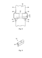
- the lock cylinder can have different designs, for example of the kind that is shown in Fig 2 or the kind that is shown in Fig 9 .
- lock cylinders with a circular cross-section are known. Such lock cylinders often fill substantially the whole hole in the door. According to the present invention it is however the first member which substantially fills the hole in the door. The lock cylinder is thus only configured to be positioned in the first recess in the first part. The cross-sectional area of the first recess is thus substantially smaller than the cross-sectional area of the whole first part. It is possible to configure the first part according to the present invention for receiving a lock cylinder which has a substantially circular cross-section. According to preferred embodiments the lock cylinder has however another cross-sectional shape, for example an oval cross-sectional shape, such as the lock cylinder which is shown in Fig 2 , or the cross-sectional shape that the lock cylinder shown in Fig 9 has.
- longitudinal direction is in this document meant a direction for the lock which in a mounted state is substantially perpendicular to the door surface.
- a central axis of the lock cylinder and a central axis of the first part thus extend in the longitudinal direction in a mounted state.
- the cross-direction, and cross-sectional dimension, and radial direction mean a direction which is perpendicular to the longitudinal direction, i.e. a direction which is substantially parallel with the door surface on the inside or the outside of the door.
- the first part comprises a third hole or a recess and wherein the second part comprises a fourth hole or a recess, wherein the lock protection is configured to interact with said blocking means in the form of a body which is configured such that it, in a blocked state, extends from said third hole or recess in the first part to said fourth hole or recess in the second part for locking the second part relative to the first part by extending into both said third hole or a recess and said fourth hole or recess.
- the parts can be locked relative to each other in a simple and secure manner.
- said body is a pin or a ball.
- a pin or ball is easy to manufacture and is easy to arrange in said holes or recesses.
- said third hole or recess in the first part is a hole which extends from the first recess to and through the substantially cylindrical outer surface.
- the third hole extends substantially perpendicular to the longitudinal direction. This is an advantageous arrangement of the third hole, which enables a simple and secure arrangement of the blocking means.
- said third hole has a length I and wherein the lock protection is configured to interact with said blocking means in the form of said body which has an extension L which is longer than I, such that the body in a blocked state protrudes from the substantially cylindrical outer surface into said fourth hole or recess in the second part.
- said body has a substantially smooth non-threaded outside and wherein the lock protection is dimensioned such that said body with the extension L, in a mounted state when a lock cylinder is positioned in the first recess, is prevented by the lock cylinder from slipping out from said third hole in the first recess and wherein the distance from the outer surface of the lock cylinder, at the third hole, to the fourth hole or recess is less than L, wherein it is ensured that the body with the extension L protrudes from the substantially cylindrical outer surface into said fourth hole or recess.
- the lock protection is thus dimensioned for in a simple manner ensuring that a blocking means with a length L is securely held in position in order to lock the parts relative to each other.
- said fourth hole or recess in the second part is a recess which extends into the second part from said second hole.
- the depth of the recess into the second part in radial direction from the second hole is suitably less than L, which means that a body with the length L by necessity extends into the third hole in order to lock the second part relative to the first part.
- the recess in the second part has an extension in the longitudinal direction which is at least 1.50 times the length of the extension of the third hole in the longitudinal direction.
- the second part is moved in the longitudinal direction and to be locked in different positions with the help of one and the same blocking means, which is positioned in one and the same third hole in the first part.
- the recess for the blocking means in the second part has an extension in the longitudinal direction which is at least 2 times the length of the extension of the third hole in the longitudinal direction.
- the first part can have a plurality of holes or recesses for the blocking means, in order to enable locking of the first and second parts in a plurality of positions relative to each other.
- the first part comprises at least one fifth hole which extends from the substantially cylindrical outer surface in to the first recess, wherein said fifth hole is configured for receiving a further blocking means for locking the lock cylinder relative to the first part.
- the lock cylinder can thus be locked relative to the first part and also relative to the second part, since the blocking means locks the first and the second part relative to each other.
- the fifth hole is preferably threaded and the further blocking means has a corresponding outer thread such that it can be screwed into the fifth hole in order to grip into the lock cylinder and to lock it relative to the first part.
- the second side of the first part comprises at least two threaded screw holes for receiving screws which in a mounted state are screwed into these screw holes in the first part for fastening this part to the door, wherein the first part does not comprise any through screw holes which extend out through the first side, and wherein the first side only has one hole, namely said first hole.
- the first part is configured for in a mounted state protruding out from the outside of the door
- the lock protection comprises a third part which has a third side, which in a mounted state is positioned on the inside of the door, wherein the third part is configured for in a mounted state being connected to the first part.
- the third part can be provided with a handle in order to make it possible to open the door from the inside.
- the third part can be configured such that the door is to be opened and closed with a key also from the inside.
- the third part comprises at least two holes for screws, which holes extend through the third part from the third side, wherein these holes are configured for screws which in a mounted state extend from the third side, where the screw heads are positioned, through the third part and into the first part for connecting the third part with the first part. In this manner the parts are securely held in position at the door.
- the third part also has a fourth side, which in a mounted state lies in the door, and a substantially cylindrical outer surface which connects said third and fourth sides and which in a mounted state to a considerable extent lies in the hole in the door, but which at the end nearest the third side protrudes from the door on its inside, wherein said third part has a recess, with a cross-sectional dimension adapted to receive a lock cylinder, which recess extends from the fourth side towards the third side but not all the way to the third side, but where a hole which has a smaller cross-sectional dimension than the recess and than the lock cylinder, extends from said recess out through the third side, wherein the hole is configured such that in a mounted state a key via the hole can interact with the lock cylinder which is positioned in the recess, either in that the key is inserted into a keyhole in the lock cylinder or in that the key in another manner communicates with the lock cylinder, wherein the lock protection comprises
- the lock protection also comprises said blocking means which is adapted to lock the second part relative to the first part.
- said blocking means which is adapted to lock the second part relative to the first part.
- the second part can thus be locked relative to the first part.
- the invention can of course suitably also comprise at least a blocking means for locking the fourth part relative to the third part.
- the lock protection also comprises one or more lock cylinders which are adapted to be arranged in the first and/or the third part.
- the invention also comprises one or more of said further blocking means for locking a lock cylinder relative to the first part and/or the third part.
- the lock protection can also comprise a plurality of said second, substantially ring-shaped, part of different dimensions, in particular different thickness in the longitudinal direction in order to fit to different construction cases.
- Another aspect of the invention concerns a use of a lock protection according to any one of the preceding embodiments. This use comprises to:
- a lock protection with the advantages which have been described above may thus through this use be applied to a door in order to fulfil the function as lock protection.
- the invention also concerns a first and second part, respectively, such as defined in any one of the preceding embodiments, configured for use in the lock protection according to any one of the preceding embodiments.
- Such parts have the advantages that have been described above.
- the lock protection according to the invention is configured to protect a lock cylinder 20, 22 (see Fig 2 and 9 ) which in a mounted state partly can protrude from a door surface 24 (see Fig 8 ).
- the lock protection comprises a first part 28 and a second, ring-shaped part 46.
- the first part has a first side 30, which in a mounted state lies outside the door surface 24, a second side 32, which in a mounted state lies in the door 34, and a substantially cylindrical outer surface 36 which connects the first 30 and the second 32 side.
- the cylindrical surface 36 lies in a mounted state to a considerable extent in a hole 38 in the door 34, but the end which lies nearest the first side 30 protrudes from the door 34.
- the first part 28 has a first recess 40 which is adapted to receive a lock cylinder 20, 22.
- the recess 40 extends from the second side 32 towards the first side 30.
- the recess 40 does however not reach all the way to the first side 30.
- There is however a first hole 42 which has a smaller cross-sectional dimension than the first recess 40 and a smaller cross-sectional dimension than the lock cylinder 20, 22.
- This first hole 42 extends from the first recess 40 out through the first side 30.
- the hole 42 is sufficiently large such that a key can be inserted in through the hole 42 in order to, in a mounted state, be inserted into the keyhole 44 of the lock cylinder 20, 22 which then is positioned in the first recess 40.
- the hole 42 is however so small that it is impossible to get the lock cylinder 20, 22 out through the hole 42.
- the first part 28 is provided with a thread 54 on the cylindrical outer surface 36.
- the first part 28 also has a number of holes (which are here called fifth holes) 62 which extend from the cylindrical surface 36 in to the first recess 40.
- These fifth holes 62 are according to this embodiment threaded and configured to receive a blocking means 64 in the form of a threaded screw which can be screwed in through the fifth hole 62 in order to lock the lock cylinder 20, 22 relative to the first part 28, when the lock cylinder 20, 22 is arranged in the first recess 40.
- a blocking means 64 in the form of a threaded screw which can be screwed in through the fifth hole 62 in order to lock the lock cylinder 20, 22 relative to the first part 28, when the lock cylinder 20, 22 is arranged in the first recess 40.
- two such fifth holes 62 are shown, but preferably there are corresponding holes on the other side of the part 28. This fact is indicated by two further lock screws 64.
- the second part 46 has a round hole 48.
- a thread 56 is arranged on the second part 46.
- the thread 56 is turned inwards towards the hole 48.
- the hole 48 is adapted to the cylindrical surface 36 of the first part 28, in such a manner that the second part 46 can be moved to different positions along the cylindrical surface 36. This is done according to this embodiment in that the thread 54 on the first part 28 interacts with the thread 56 on the second part 46.
- the second part 46 can thus be moved in the longitudinal direction along the first part 28 in that the second part 46 by means of the threaded connection is rotated relative to the first part 28.
- the first 28 and the second 46 part are configured to interact with a blocking means 50 which is configured for locking the second part 46 relative to the first part 28 in a selected position.
- the blocking means 50 is according to this embodiment a body 50 in the form of a smooth ball.
- the ball 50 has an extension (diameter) L.
- the first part 28 has at least one hole 58 (according to this example two such holes 58) with a size which is adapted to the ball 50.
- the hole 58 extends from the first recess 40 to and through the cylindrical surface 36.
- the diameter of the hole 58 is thus somewhat larger than the diameter of the ball 50, such that the ball 50 can be moved through the hole 58.
- the second part 46 is according to this embodiment provided with four recesses 60 which are adapted to the ball 50, such that the ball 50 can extend into a recess 60.
- a recess 60 is arranged over one of the holes 58, the second part 46 can be locked relative to the first part 28 in that a ball is introduced into the hole 58 from the first recess 40, wherein the ball is arranged such that it extends from the hole 58 into the recess 60.
- the thickness of the wall through the first part 28 where the hole 58 is positioned is such that the hole has a length I. This length I is less than the diameter L of the ball 50.
- the recess 60 in the second part 46 has an extension in the longitudinal direction which is about two times the length of the extension of the hole 58 in the longitudinal direction (the diameter of the hole).
- the second part 46 can thereby be moved to different positions along the first part 28 and the recess 60 can still be arranged opposite a hole 58.
- the possibility to adjust the second part 46 relative to the first part 28 can be further increased. Since the second part 46 according to this embodiment has four recesses 60, the second part 46 can also be locked in four positions per revolution. If the pitch of the thread 36, 56 for example is 1 mm this means that the second part 46 can be locked relative to the first part 28 in positions which in the longitudinal direction only differ 0.25 mm from each other.
- the first part 28 is on the other side 32 provided with two threaded screw holes 66 for receiving screws 68 (see Fig 8 ).
- the screws 68 are intended to fasten the first part 28 at the door 34.
- the first part 28 does not have any through screw holes which extend out through the first side 30.
- the first side 30 only has one hole, namely the hole 42 which is intended for a key. Thereby a high security against manipulation of the device is achieved.
- the first part 28 is configured for in a mounted state protruding from the outside 24 of the door 34.
- the second part 46 has a surface 52 which in a mounted state abuts, directly or via one or more further elements, against the door surface 24 around the hole 38 in the door 34.
- the lock protection suitably comprises a third part 70 (see Fig 6 and 7 ) which has a third side 72 which in a mounted state is positioned on the inside 26 of the door 34.
- the third part 70 can in a mounted state be connected with the first part 28 with the help of said screws 68.
- the third part 70 has a design which is similar to the design of the first part 28. However, the third part 70 has two through holes 74 for screws. These holes 74 extend from the third side 72 through the third part 70 and out through the fourth side 78. The third part can also have further holes 75 for screws which are intended to be screwed through a lock cylinder 20, 22 when this is positioned in a recess 82 in the third part 70.
- the fourth side 78 lies in the door 34.
- the third part 70 has a cylindrical outer surface 80 which connects the third 72 and the fourth 78 side.
- this cylindrical surface 80 is suitably provided with a thread in a corresponding manner as concerning the first part 28.
- the cylindrical surface 80 lies in a mounted state to a considerable extent in the hole 38 in the door 34.
- the end nearest the third side 72 protrudes however from the door on its inside 26.
- the recess 82 extends from the fourth side 78 towards the third side 72 but not all the way to the third side 72.
- a hole 84 adapted for the keyhole 44 in the lock cylinder 20, 22, which hole 84 has a smaller cross-sectional dimension than the recess 82 and than the lock cylinder 20, 22, extends however from the recess 82 out through the third side 72.
- a key may thus be inserted through the hole 84 in order to be inserted into the keyhole 44 of the lock cylinder 20, 22 which is positioned in the recess 82.
- the lock protection also has a fourth part 86.
- This fourth part 86 is configured in the same manner as the second part 46.
- the fourth part 86 thus has a hole 48 which is adapted to the cylindrical surface 80 of the third part 70.
- the fourth part 86 also has a thread 56 and can thus be moved to different positions along the cylindrical surface 80.
- the third part 70 and the fourth part 86 are configured to interact with a blocking means 50 in the form of a ball in order to lock the fourth part 86 relative to the third part 70 in a selected position.
- the fourth part 86 has a surface 52 which in a mounted state is configured to abut against the door surface 26 on the inside of the door, around the hole 38 in the door 34.
- All parts can be fastened at the door by screws 68 which connect the third part 70 with the first part 28.
- the screw heads 76 on the screws 68 can rest in recesses around the holes 75.
- the invention also concerns a use of a lock protection according to the previous embodiment.
- the use comprises to:
- the third part can for example comprise a handle.
- the third part 70 can be configured in the manner which has been described above. That is, the third part 70 can be connected and locked relative to a fourth part 86.
- the thus obtained unit can thus be arranged from the inside 26 of the door 34, such that a surface 52 of the fourth part 86 abuts against the door surface 26.
Landscapes
- Engineering & Computer Science (AREA)
- Mechanical Engineering (AREA)
- Structural Engineering (AREA)
- Lock And Its Accessories (AREA)
Applications Claiming Priority (1)
| Application Number | Priority Date | Filing Date | Title |
|---|---|---|---|
| SE1051163A SE535024C2 (sv) | 2010-11-08 | 2010-11-08 | Låsskydd för ett cylinderlås |
Publications (3)
| Publication Number | Publication Date |
|---|---|
| EP2450507A2 true EP2450507A2 (de) | 2012-05-09 |
| EP2450507A3 EP2450507A3 (de) | 2016-05-18 |
| EP2450507B1 EP2450507B1 (de) | 2019-06-26 |
Family
ID=44903107
Family Applications (1)
| Application Number | Title | Priority Date | Filing Date |
|---|---|---|---|
| EP11186332.0A Active EP2450507B1 (de) | 2010-11-08 | 2011-10-24 | Schlossschutz für ein Zylinderschloss |
Country Status (3)
| Country | Link |
|---|---|
| EP (1) | EP2450507B1 (de) |
| DK (1) | DK2450507T3 (de) |
| SE (1) | SE535024C2 (de) |
Cited By (2)
| Publication number | Priority date | Publication date | Assignee | Title |
|---|---|---|---|---|
| CN109763695A (zh) * | 2019-04-02 | 2019-05-17 | 温州市通用锁具有限公司 | 一种锁芯防护机构 |
| NO20210940A1 (no) * | 2021-07-26 | 2023-01-27 | Boyesen & Munthe As | Adapter for låsesylinder |
Citations (2)
| Publication number | Priority date | Publication date | Assignee | Title |
|---|---|---|---|---|
| GB2216944A (en) | 1987-12-22 | 1989-10-18 | Assa Ab | Cylinder lock fittings |
| US5291767A (en) | 1992-07-23 | 1994-03-08 | Best Lock Corporation | Protective lock cylinder mounting assembly |
Family Cites Families (4)
| Publication number | Priority date | Publication date | Assignee | Title |
|---|---|---|---|---|
| FR2784413B1 (fr) * | 1998-10-08 | 2001-01-05 | Laperche Sa | Dispositif de protection reglable de cylindre de serrure |
| US20020026817A1 (en) * | 2000-06-14 | 2002-03-07 | Norment Security Group, Inc., A Delware Corporation Airteq Division | Quick lock mount |
| DE10101365B4 (de) * | 2001-01-13 | 2015-09-17 | Assa-Ruko Sicherheitssysteme Gmbh | Kernschutzbelag |
| DE20314117U1 (de) * | 2003-09-11 | 2004-01-08 | Hofmann, Gerhard | Betätigungsvorrichtung für eine Teleskop-Sicherheitstürschlossrosette |
-
2010
- 2010-11-08 SE SE1051163A patent/SE535024C2/sv unknown
-
2011
- 2011-10-24 EP EP11186332.0A patent/EP2450507B1/de active Active
- 2011-10-24 DK DK11186332.0T patent/DK2450507T3/da active
Patent Citations (2)
| Publication number | Priority date | Publication date | Assignee | Title |
|---|---|---|---|---|
| GB2216944A (en) | 1987-12-22 | 1989-10-18 | Assa Ab | Cylinder lock fittings |
| US5291767A (en) | 1992-07-23 | 1994-03-08 | Best Lock Corporation | Protective lock cylinder mounting assembly |
Cited By (4)
| Publication number | Priority date | Publication date | Assignee | Title |
|---|---|---|---|---|
| CN109763695A (zh) * | 2019-04-02 | 2019-05-17 | 温州市通用锁具有限公司 | 一种锁芯防护机构 |
| WO2020199358A1 (zh) * | 2019-04-02 | 2020-10-08 | 温州市通用锁具有限公司 | 一种锁芯防护机构 |
| NO20210940A1 (no) * | 2021-07-26 | 2023-01-27 | Boyesen & Munthe As | Adapter for låsesylinder |
| NO349149B1 (no) * | 2021-07-26 | 2025-10-13 | Boyesen & Munthe As | Adapter for låsesylinder |
Also Published As
| Publication number | Publication date |
|---|---|
| EP2450507A3 (de) | 2016-05-18 |
| SE1051163A1 (sv) | 2012-03-20 |
| SE535024C2 (sv) | 2012-03-20 |
| DK2450507T3 (da) | 2019-10-07 |
| EP2450507B1 (de) | 2019-06-26 |
Similar Documents
| Publication | Publication Date | Title |
|---|---|---|
| US7428836B2 (en) | Door lock having reinforced strength | |
| US20080086844A1 (en) | Knob for an electronic locking cylinder | |
| US20120210756A1 (en) | High Security Moving Mass Lock System | |
| EP2504506B1 (de) | Verbindungsvorrichtung und schlossmontagevorrichtung mit einer derartigen verbindungsvorrichtung | |
| GB2424918A (en) | Removable locking unit including electronic module and power source | |
| CN103649446A (zh) | 圆筒锁 | |
| US20100180651A1 (en) | Lock device | |
| CN112262246A (zh) | 用于操作锁的电驱动机构 | |
| KR20140079325A (ko) | 무허가 손잡이 제거를 방지하기 위해 보안 고정나사 구성을 갖는 잠금장치 조립체 | |
| EP2450507B1 (de) | Schlossschutz für ein Zylinderschloss | |
| EP2546436B1 (de) | Türverriegelungsvorrichtung, tür und verfahren zur montage einer türverriegelungskonstruktion | |
| EP2865825B1 (de) | Zylinderschlossanordnung | |
| US8056380B2 (en) | Cylinder lock unit with an extra locking pin | |
| DK2865826T3 (en) | Lock cylinder-device | |
| CN110226015A (zh) | 用于可移除的锁芯的壳体 | |
| EP1944437B1 (de) | Untrennbarer Schließzylinder | |
| EP2278099A1 (de) | Zylinderschloss | |
| DK2865827T3 (en) | A cylinder lock arrangement | |
| EP4424953B1 (de) | Befestigungsanordnung für endstück und verriegelungsanordnung | |
| JP4331564B2 (ja) | 錠装置 | |
| DK2865830T3 (en) | Cylinder locking device | |
| US7296446B1 (en) | Lock assembly | |
| KR200249615Y1 (ko) | 자물쇠용 실린더 | |
| KR200412411Y1 (ko) | 컨테이너의 도어 이중잠금장치 | |
| EP1411197B1 (de) | Riegel |
Legal Events
| Date | Code | Title | Description |
|---|---|---|---|
| PUAI | Public reference made under article 153(3) epc to a published international application that has entered the european phase |
Free format text: ORIGINAL CODE: 0009012 |
|
| AK | Designated contracting states |
Kind code of ref document: A2 Designated state(s): AL AT BE BG CH CY CZ DE DK EE ES FI FR GB GR HR HU IE IS IT LI LT LU LV MC MK MT NL NO PL PT RO RS SE SI SK SM TR |
|
| AX | Request for extension of the european patent |
Extension state: BA ME |
|
| PUAL | Search report despatched |
Free format text: ORIGINAL CODE: 0009013 |
|
| AK | Designated contracting states |
Kind code of ref document: A3 Designated state(s): AL AT BE BG CH CY CZ DE DK EE ES FI FR GB GR HR HU IE IS IT LI LT LU LV MC MK MT NL NO PL PT RO RS SE SI SK SM TR |
|
| AX | Request for extension of the european patent |
Extension state: BA ME |
|
| RIC1 | Information provided on ipc code assigned before grant |
Ipc: E05B 15/02 20060101ALI20160408BHEP Ipc: E05B 17/20 20060101ALI20160408BHEP Ipc: E05B 9/08 20060101AFI20160408BHEP |
|
| STAA | Information on the status of an ep patent application or granted ep patent |
Free format text: STATUS: REQUEST FOR EXAMINATION WAS MADE |
|
| 17P | Request for examination filed |
Effective date: 20161117 |
|
| RBV | Designated contracting states (corrected) |
Designated state(s): AL AT BE BG CH CY CZ DE DK EE ES FI FR GB GR HR HU IE IS IT LI LT LU LV MC MK MT NL NO PL PT RO RS SE SI SK SM TR |
|
| STAA | Information on the status of an ep patent application or granted ep patent |
Free format text: STATUS: EXAMINATION IS IN PROGRESS |
|
| 17Q | First examination report despatched |
Effective date: 20180816 |
|
| GRAP | Despatch of communication of intention to grant a patent |
Free format text: ORIGINAL CODE: EPIDOSNIGR1 |
|
| STAA | Information on the status of an ep patent application or granted ep patent |
Free format text: STATUS: GRANT OF PATENT IS INTENDED |
|
| INTG | Intention to grant announced |
Effective date: 20190129 |
|
| GRAS | Grant fee paid |
Free format text: ORIGINAL CODE: EPIDOSNIGR3 |
|
| GRAA | (expected) grant |
Free format text: ORIGINAL CODE: 0009210 |
|
| STAA | Information on the status of an ep patent application or granted ep patent |
Free format text: STATUS: THE PATENT HAS BEEN GRANTED |
|
| AK | Designated contracting states |
Kind code of ref document: B1 Designated state(s): AL AT BE BG CH CY CZ DE DK EE ES FI FR GB GR HR HU IE IS IT LI LT LU LV MC MK MT NL NO PL PT RO RS SE SI SK SM TR |
|
| REG | Reference to a national code |
Ref country code: GB Ref legal event code: FG4D |
|
| REG | Reference to a national code |
Ref country code: CH Ref legal event code: EP |
|
| REG | Reference to a national code |
Ref country code: DE Ref legal event code: R096 Ref document number: 602011059982 Country of ref document: DE |
|
| REG | Reference to a national code |
Ref country code: AT Ref legal event code: REF Ref document number: 1148458 Country of ref document: AT Kind code of ref document: T Effective date: 20190715 |
|
| REG | Reference to a national code |
Ref country code: IE Ref legal event code: FG4D |
|
| REG | Reference to a national code |
Ref country code: DK Ref legal event code: T3 Effective date: 20191003 |
|
| REG | Reference to a national code |
Ref country code: NL Ref legal event code: MP Effective date: 20190626 |
|
| PG25 | Lapsed in a contracting state [announced via postgrant information from national office to epo] |
Ref country code: HR Free format text: LAPSE BECAUSE OF FAILURE TO SUBMIT A TRANSLATION OF THE DESCRIPTION OR TO PAY THE FEE WITHIN THE PRESCRIBED TIME-LIMIT Effective date: 20190626 Ref country code: LT Free format text: LAPSE BECAUSE OF FAILURE TO SUBMIT A TRANSLATION OF THE DESCRIPTION OR TO PAY THE FEE WITHIN THE PRESCRIBED TIME-LIMIT Effective date: 20190626 Ref country code: AL Free format text: LAPSE BECAUSE OF FAILURE TO SUBMIT A TRANSLATION OF THE DESCRIPTION OR TO PAY THE FEE WITHIN THE PRESCRIBED TIME-LIMIT Effective date: 20190626 Ref country code: SE Free format text: LAPSE BECAUSE OF FAILURE TO SUBMIT A TRANSLATION OF THE DESCRIPTION OR TO PAY THE FEE WITHIN THE PRESCRIBED TIME-LIMIT Effective date: 20190626 |
|
| REG | Reference to a national code |
Ref country code: LT Ref legal event code: MG4D Ref country code: NO Ref legal event code: T2 Effective date: 20190626 |
|
| PG25 | Lapsed in a contracting state [announced via postgrant information from national office to epo] |
Ref country code: BG Free format text: LAPSE BECAUSE OF FAILURE TO SUBMIT A TRANSLATION OF THE DESCRIPTION OR TO PAY THE FEE WITHIN THE PRESCRIBED TIME-LIMIT Effective date: 20190926 Ref country code: GR Free format text: LAPSE BECAUSE OF FAILURE TO SUBMIT A TRANSLATION OF THE DESCRIPTION OR TO PAY THE FEE WITHIN THE PRESCRIBED TIME-LIMIT Effective date: 20190927 Ref country code: RS Free format text: LAPSE BECAUSE OF FAILURE TO SUBMIT A TRANSLATION OF THE DESCRIPTION OR TO PAY THE FEE WITHIN THE PRESCRIBED TIME-LIMIT Effective date: 20190626 Ref country code: LV Free format text: LAPSE BECAUSE OF FAILURE TO SUBMIT A TRANSLATION OF THE DESCRIPTION OR TO PAY THE FEE WITHIN THE PRESCRIBED TIME-LIMIT Effective date: 20190626 |
|
| REG | Reference to a national code |
Ref country code: AT Ref legal event code: MK05 Ref document number: 1148458 Country of ref document: AT Kind code of ref document: T Effective date: 20190626 |
|
| PG25 | Lapsed in a contracting state [announced via postgrant information from national office to epo] |
Ref country code: AT Free format text: LAPSE BECAUSE OF FAILURE TO SUBMIT A TRANSLATION OF THE DESCRIPTION OR TO PAY THE FEE WITHIN THE PRESCRIBED TIME-LIMIT Effective date: 20190626 Ref country code: EE Free format text: LAPSE BECAUSE OF FAILURE TO SUBMIT A TRANSLATION OF THE DESCRIPTION OR TO PAY THE FEE WITHIN THE PRESCRIBED TIME-LIMIT Effective date: 20190626 Ref country code: SK Free format text: LAPSE BECAUSE OF FAILURE TO SUBMIT A TRANSLATION OF THE DESCRIPTION OR TO PAY THE FEE WITHIN THE PRESCRIBED TIME-LIMIT Effective date: 20190626 Ref country code: PT Free format text: LAPSE BECAUSE OF FAILURE TO SUBMIT A TRANSLATION OF THE DESCRIPTION OR TO PAY THE FEE WITHIN THE PRESCRIBED TIME-LIMIT Effective date: 20191028 Ref country code: RO Free format text: LAPSE BECAUSE OF FAILURE TO SUBMIT A TRANSLATION OF THE DESCRIPTION OR TO PAY THE FEE WITHIN THE PRESCRIBED TIME-LIMIT Effective date: 20190626 Ref country code: CZ Free format text: LAPSE BECAUSE OF FAILURE TO SUBMIT A TRANSLATION OF THE DESCRIPTION OR TO PAY THE FEE WITHIN THE PRESCRIBED TIME-LIMIT Effective date: 20190626 Ref country code: NL Free format text: LAPSE BECAUSE OF FAILURE TO SUBMIT A TRANSLATION OF THE DESCRIPTION OR TO PAY THE FEE WITHIN THE PRESCRIBED TIME-LIMIT Effective date: 20190626 |
|
| PG25 | Lapsed in a contracting state [announced via postgrant information from national office to epo] |
Ref country code: SM Free format text: LAPSE BECAUSE OF FAILURE TO SUBMIT A TRANSLATION OF THE DESCRIPTION OR TO PAY THE FEE WITHIN THE PRESCRIBED TIME-LIMIT Effective date: 20190626 Ref country code: IS Free format text: LAPSE BECAUSE OF FAILURE TO SUBMIT A TRANSLATION OF THE DESCRIPTION OR TO PAY THE FEE WITHIN THE PRESCRIBED TIME-LIMIT Effective date: 20191026 Ref country code: ES Free format text: LAPSE BECAUSE OF FAILURE TO SUBMIT A TRANSLATION OF THE DESCRIPTION OR TO PAY THE FEE WITHIN THE PRESCRIBED TIME-LIMIT Effective date: 20190626 Ref country code: IT Free format text: LAPSE BECAUSE OF FAILURE TO SUBMIT A TRANSLATION OF THE DESCRIPTION OR TO PAY THE FEE WITHIN THE PRESCRIBED TIME-LIMIT Effective date: 20190626 |
|
| PG25 | Lapsed in a contracting state [announced via postgrant information from national office to epo] |
Ref country code: TR Free format text: LAPSE BECAUSE OF FAILURE TO SUBMIT A TRANSLATION OF THE DESCRIPTION OR TO PAY THE FEE WITHIN THE PRESCRIBED TIME-LIMIT Effective date: 20190626 |
|
| PG25 | Lapsed in a contracting state [announced via postgrant information from national office to epo] |
Ref country code: PL Free format text: LAPSE BECAUSE OF FAILURE TO SUBMIT A TRANSLATION OF THE DESCRIPTION OR TO PAY THE FEE WITHIN THE PRESCRIBED TIME-LIMIT Effective date: 20190626 |
|
| REG | Reference to a national code |
Ref country code: DE Ref legal event code: R119 Ref document number: 602011059982 Country of ref document: DE |
|
| PG25 | Lapsed in a contracting state [announced via postgrant information from national office to epo] |
Ref country code: IS Free format text: LAPSE BECAUSE OF FAILURE TO SUBMIT A TRANSLATION OF THE DESCRIPTION OR TO PAY THE FEE WITHIN THE PRESCRIBED TIME-LIMIT Effective date: 20200224 Ref country code: MC Free format text: LAPSE BECAUSE OF FAILURE TO SUBMIT A TRANSLATION OF THE DESCRIPTION OR TO PAY THE FEE WITHIN THE PRESCRIBED TIME-LIMIT Effective date: 20190626 |
|
| REG | Reference to a national code |
Ref country code: CH Ref legal event code: PL |
|
| PLBE | No opposition filed within time limit |
Free format text: ORIGINAL CODE: 0009261 |
|
| STAA | Information on the status of an ep patent application or granted ep patent |
Free format text: STATUS: NO OPPOSITION FILED WITHIN TIME LIMIT |
|
| PG2D | Information on lapse in contracting state deleted |
Ref country code: IS |
|
| PG25 | Lapsed in a contracting state [announced via postgrant information from national office to epo] |
Ref country code: DE Free format text: LAPSE BECAUSE OF NON-PAYMENT OF DUE FEES Effective date: 20200501 Ref country code: LI Free format text: LAPSE BECAUSE OF NON-PAYMENT OF DUE FEES Effective date: 20191031 Ref country code: LU Free format text: LAPSE BECAUSE OF NON-PAYMENT OF DUE FEES Effective date: 20191024 Ref country code: CH Free format text: LAPSE BECAUSE OF NON-PAYMENT OF DUE FEES Effective date: 20191031 |
|
| 26N | No opposition filed |
Effective date: 20200603 |
|
| REG | Reference to a national code |
Ref country code: BE Ref legal event code: MM Effective date: 20191031 |
|
| PG25 | Lapsed in a contracting state [announced via postgrant information from national office to epo] |
Ref country code: BE Free format text: LAPSE BECAUSE OF NON-PAYMENT OF DUE FEES Effective date: 20191031 Ref country code: SI Free format text: LAPSE BECAUSE OF FAILURE TO SUBMIT A TRANSLATION OF THE DESCRIPTION OR TO PAY THE FEE WITHIN THE PRESCRIBED TIME-LIMIT Effective date: 20190626 |
|
| GBPC | Gb: european patent ceased through non-payment of renewal fee |
Effective date: 20191024 |
|
| PG25 | Lapsed in a contracting state [announced via postgrant information from national office to epo] |
Ref country code: GB Free format text: LAPSE BECAUSE OF NON-PAYMENT OF DUE FEES Effective date: 20191024 Ref country code: IE Free format text: LAPSE BECAUSE OF NON-PAYMENT OF DUE FEES Effective date: 20191024 Ref country code: FR Free format text: LAPSE BECAUSE OF NON-PAYMENT OF DUE FEES Effective date: 20191031 |
|
| PG25 | Lapsed in a contracting state [announced via postgrant information from national office to epo] |
Ref country code: CY Free format text: LAPSE BECAUSE OF FAILURE TO SUBMIT A TRANSLATION OF THE DESCRIPTION OR TO PAY THE FEE WITHIN THE PRESCRIBED TIME-LIMIT Effective date: 20190626 |
|
| PG25 | Lapsed in a contracting state [announced via postgrant information from national office to epo] |
Ref country code: MT Free format text: LAPSE BECAUSE OF FAILURE TO SUBMIT A TRANSLATION OF THE DESCRIPTION OR TO PAY THE FEE WITHIN THE PRESCRIBED TIME-LIMIT Effective date: 20190626 Ref country code: HU Free format text: LAPSE BECAUSE OF FAILURE TO SUBMIT A TRANSLATION OF THE DESCRIPTION OR TO PAY THE FEE WITHIN THE PRESCRIBED TIME-LIMIT; INVALID AB INITIO Effective date: 20111024 |
|
| PG25 | Lapsed in a contracting state [announced via postgrant information from national office to epo] |
Ref country code: MK Free format text: LAPSE BECAUSE OF FAILURE TO SUBMIT A TRANSLATION OF THE DESCRIPTION OR TO PAY THE FEE WITHIN THE PRESCRIBED TIME-LIMIT Effective date: 20190626 |
|
| PGFP | Annual fee paid to national office [announced via postgrant information from national office to epo] |
Ref country code: FI Payment date: 20250430 Year of fee payment: 14 |
|
| PGFP | Annual fee paid to national office [announced via postgrant information from national office to epo] |
Ref country code: DK Payment date: 20250430 Year of fee payment: 14 |
|
| PGFP | Annual fee paid to national office [announced via postgrant information from national office to epo] |
Ref country code: NO Payment date: 20250502 Year of fee payment: 14 |