EP2450657A1 - Wärmetauscher, insbesondere für Kraftfahrzeug, und entsprechende Montageverfahren - Google Patents
Wärmetauscher, insbesondere für Kraftfahrzeug, und entsprechende Montageverfahren Download PDFInfo
- Publication number
- EP2450657A1 EP2450657A1 EP11188042A EP11188042A EP2450657A1 EP 2450657 A1 EP2450657 A1 EP 2450657A1 EP 11188042 A EP11188042 A EP 11188042A EP 11188042 A EP11188042 A EP 11188042A EP 2450657 A1 EP2450657 A1 EP 2450657A1
- Authority
- EP
- European Patent Office
- Prior art keywords
- distribution box
- housing
- exchanger
- exchanger according
- distribution
- Prior art date
- Legal status (The legal status is an assumption and is not a legal conclusion. Google has not performed a legal analysis and makes no representation as to the accuracy of the status listed.)
- Withdrawn
Links
- 238000000034 method Methods 0.000 title claims abstract description 13
- 238000007789 sealing Methods 0.000 claims abstract description 46
- 239000012530 fluid Substances 0.000 claims abstract description 43
- 238000009826 distribution Methods 0.000 claims description 106
- 238000005219 brazing Methods 0.000 claims description 8
- 238000003780 insertion Methods 0.000 claims description 6
- 230000037431 insertion Effects 0.000 claims description 6
- 239000003566 sealing material Substances 0.000 claims description 6
- 239000003292 glue Substances 0.000 claims description 5
- 238000005476 soldering Methods 0.000 claims description 2
- 239000000853 adhesive Substances 0.000 abstract description 3
- 230000001070 adhesive effect Effects 0.000 abstract description 3
- XLYOFNOQVPJJNP-UHFFFAOYSA-N water Substances O XLYOFNOQVPJJNP-UHFFFAOYSA-N 0.000 description 12
- 230000002093 peripheral effect Effects 0.000 description 9
- 229920001296 polysiloxane Polymers 0.000 description 4
- 230000002787 reinforcement Effects 0.000 description 4
- 238000004026 adhesive bonding Methods 0.000 description 3
- 230000000295 complement effect Effects 0.000 description 3
- 229920006335 epoxy glue Polymers 0.000 description 3
- 239000011324 bead Substances 0.000 description 2
- 239000002826 coolant Substances 0.000 description 2
- 238000001816 cooling Methods 0.000 description 2
- 239000007789 gas Substances 0.000 description 2
- 238000002347 injection Methods 0.000 description 2
- 239000007924 injection Substances 0.000 description 2
- 238000005304 joining Methods 0.000 description 2
- 229910000679 solder Inorganic materials 0.000 description 2
- 239000000243 solution Substances 0.000 description 2
- 239000004593 Epoxy Substances 0.000 description 1
- 239000012267 brine Substances 0.000 description 1
- 238000002485 combustion reaction Methods 0.000 description 1
- 239000000110 cooling liquid Substances 0.000 description 1
- 230000003247 decreasing effect Effects 0.000 description 1
- 230000006698 induction Effects 0.000 description 1
- 239000007788 liquid Substances 0.000 description 1
- 238000004519 manufacturing process Methods 0.000 description 1
- 239000000565 sealant Substances 0.000 description 1
- HPALAKNZSZLMCH-UHFFFAOYSA-M sodium;chloride;hydrate Chemical compound O.[Na+].[Cl-] HPALAKNZSZLMCH-UHFFFAOYSA-M 0.000 description 1
- 238000003466 welding Methods 0.000 description 1
Images




Classifications
-
- F—MECHANICAL ENGINEERING; LIGHTING; HEATING; WEAPONS; BLASTING
- F28—HEAT EXCHANGE IN GENERAL
- F28D—HEAT-EXCHANGE APPARATUS, NOT PROVIDED FOR IN ANOTHER SUBCLASS, IN WHICH THE HEAT-EXCHANGE MEDIA DO NOT COME INTO DIRECT CONTACT
- F28D9/00—Heat-exchange apparatus having stationary plate-like or laminated conduit assemblies for both heat-exchange media, the media being in contact with different sides of a conduit wall
- F28D9/0031—Heat-exchange apparatus having stationary plate-like or laminated conduit assemblies for both heat-exchange media, the media being in contact with different sides of a conduit wall the conduits for one heat-exchange medium being formed by paired plates touching each other
- F28D9/0043—Heat-exchange apparatus having stationary plate-like or laminated conduit assemblies for both heat-exchange media, the media being in contact with different sides of a conduit wall the conduits for one heat-exchange medium being formed by paired plates touching each other the plates having openings therein for circulation of at least one heat-exchange medium from one conduit to another
-
- F—MECHANICAL ENGINEERING; LIGHTING; HEATING; WEAPONS; BLASTING
- F28—HEAT EXCHANGE IN GENERAL
- F28F—DETAILS OF HEAT-EXCHANGE AND HEAT-TRANSFER APPARATUS, OF GENERAL APPLICATION
- F28F9/00—Casings; Header boxes; Auxiliary supports for elements; Auxiliary members within casings
- F28F9/001—Casings in the form of plate-like arrangements; Frames enclosing a heat exchange core
-
- F—MECHANICAL ENGINEERING; LIGHTING; HEATING; WEAPONS; BLASTING
- F28—HEAT EXCHANGE IN GENERAL
- F28F—DETAILS OF HEAT-EXCHANGE AND HEAT-TRANSFER APPARATUS, OF GENERAL APPLICATION
- F28F9/00—Casings; Header boxes; Auxiliary supports for elements; Auxiliary members within casings
- F28F9/02—Header boxes; End plates
- F28F9/0219—Arrangements for sealing end plates into casing or header box; Header box sub-elements
-
- F—MECHANICAL ENGINEERING; LIGHTING; HEATING; WEAPONS; BLASTING
- F28—HEAT EXCHANGE IN GENERAL
- F28D—HEAT-EXCHANGE APPARATUS, NOT PROVIDED FOR IN ANOTHER SUBCLASS, IN WHICH THE HEAT-EXCHANGE MEDIA DO NOT COME INTO DIRECT CONTACT
- F28D21/00—Heat-exchange apparatus not covered by any of the groups F28D1/00 - F28D20/00
- F28D2021/0019—Other heat exchangers for particular applications; Heat exchange systems not otherwise provided for
- F28D2021/008—Other heat exchangers for particular applications; Heat exchange systems not otherwise provided for for vehicles
- F28D2021/0082—Charged air coolers
-
- F—MECHANICAL ENGINEERING; LIGHTING; HEATING; WEAPONS; BLASTING
- F28—HEAT EXCHANGE IN GENERAL
- F28F—DETAILS OF HEAT-EXCHANGE AND HEAT-TRANSFER APPARATUS, OF GENERAL APPLICATION
- F28F2230/00—Sealing means
-
- F—MECHANICAL ENGINEERING; LIGHTING; HEATING; WEAPONS; BLASTING
- F28—HEAT EXCHANGE IN GENERAL
- F28F—DETAILS OF HEAT-EXCHANGE AND HEAT-TRANSFER APPARATUS, OF GENERAL APPLICATION
- F28F2275/00—Fastening; Joining
- F28F2275/02—Fastening; Joining by using bonding materials; by embedding elements in particular materials
- F28F2275/025—Fastening; Joining by using bonding materials; by embedding elements in particular materials by using adhesives
Definitions
- the invention relates to a heat exchanger, in particular for a motor vehicle.
- the invention also relates to methods for assembling such a heat exchanger.
- a heat exchanger for example used in the automotive industry and more specifically in an internal combustion engine of a motor vehicle, comprises heat exchange elements and fluid flow in which heat exchanging fluids circulate. between them.
- the heat exchange elements may for example comprise tubes or plates, gas flow disturbing fins and / or fluid flow disruptors or the like.
- Exchangers comprising a bundle of plates arranged parallel to each other on one or more rows parallel to each other, these plates being arranged to define on the one hand the first circulation channels of a first fluid and on the other hand second circulation channels of a second fluid by exchanging heat with the first fluid.
- an exchanger comprises a housing for receiving the exchange elements or, according to an alternative embodiment, the exchange elements are mounted in a housing connected to a circuit of the first fluid.
- the object of the invention is to improve the performance of known heat exchangers. Another object of the invention is to reduce the bulk of such heat exchangers.
- said bundle is assembled by brazing and said at least one distribution box is assembled by gluing to said bundle.
- the invention relates to a heat exchanger, in particular for cooling the supercharging air for a heat engine, such as a diesel engine of a motor vehicle.
- Such an exchanger may be an exchanger called "air-water”, that is to say an exchanger in which the fluids that exchange heat are air and water.
- the water is preferably water from the so-called “low temperature” cooling circuit of said engine; it is typically brine.
- the heat exchange bundle 3 comprises a stack of plates 11.
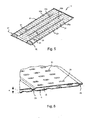
- a plate 11 (better visible on the figure 5 ) has a generally rectangular shape.
- the plates 11 are arranged in pairs.
- the stack of plates 11 makes it possible to delimit on the one hand first channels 13 ( figure 4 ) for the circulation of the first fluid, and secondly second channels 15 for the circulation of the second fluid ( figure 6 ).
- the plates 11 arranged in pairs define a space e for delimiting a second channel 15 for the circulation of the second fluid, the coolant in the present example.
- the second channels 15 for the circulation of the second fluid are thus defined by two adjacent plates of a pair.
- the first channels 13 they are delimited each time between the plates 11 provided vis-à-vis two pairs of adjacent plates 11.
- disturbance fins 16 can be provided ( figure 4 ), for example of substantially undulating shape and brazed to the plates, so as to disturb the flow of air in these first channels 13 by increasing the exchange surface.
- the plates 11 respectively comprise two openings, for example inlet pipes 17 and outlet 19, for the passage of the second fluid.
- the tubings 17, 19 of a plate 11 communicate respectively with the tubings 17, 19 of a plate 11 of an adjacent pair, for example by interlocking, to allow the circulation of the second fluid between the plates 11.
- the plates 11 may have disruptive bosses 21 of the second fluid flowing in the second channels 15, so as to improve the heat exchange.
- the plates 11 may also comprise longitudinal ribs 23 joining two plates 11 of a pair so as to define circulation passes 25a to 25d ( figure 5 ) for the second fluid.
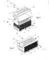
- these plates 11 with possibly disturbing fins 16 are mounted in a receiving housing 5 as mentioned above, having at least one opening 6 for assembling the bundle 3 with one or more distribution boxes 7, 9.
- the casing 5 has inlet orifices 27 and outlet ports 29 of water in the exchanger 1, associated with a water circuit in which the exchanger 1 is mounted and communicating respectively with the tubes 17, 19 of the ductwork. exchange 3.
- this receiving casing 5 is formed of a first inner casing 31 and a second outer casing 33.
- the outer casing 33 may have openings 34 which facilitate brazing.
- Each housing 31,33 comprises for example two assembled half-housings. So, as this is best seen on the figure 3 the first inner casing 31 may comprise two inner half-casings 31a and 31b assembled, for example by brazing, to form the inner casing 31.
- the second outer casing 33 may comprise two outer half-casings 33a and 33b assembled, for example by brazing, to form the outer casing 33.
- These inner casings 31 and outer casings 33 are arranged to form a receiving groove 35 a heel 37 of a distribution box 7.9.
- the beam and more particularly the receiving housing is arranged to form at least one receiving groove of the sealing means.
- the heat exchanger 1 comprises on the one hand an inlet casing 7 of the first fluid, the air in the present example, and on the other hand an outlet distribution casing 9 of the first fluid, the water in the present example, the casing 5 thus has two openings 6 on either side of the beam 3.
- the two inner casings 31 and outer 33 are arranged so as to form such a groove 35 on each side of the exchanger 1 to receive on the one hand the heel 37 of the inlet housing 7 of the first fluid, the air in the present example, and on the other hand the heel of the outlet housing 9 of the first fluid, the water in this example (see Figures 1 and 2 ).
- a sealing means (not shown) is arranged in the groove 35 between the bundle 3 and the distribution boxes 7, 9. This groove 35 thus forms a sealing groove.
- the sealing means may be a seal formed by glue, such as silicone for example or epoxy glue, deposited in the sealing groove between the bundle 3 and each distribution box 7, 9. Moreover, bonding allows greater tolerance than mechanical seals.
- glue such as silicone for example or epoxy glue
- the watertightness is done on two sides of the exchanger 1 between the distribution boxes 7, 9 and the bundle 3.
- the inner casing 31 has folded peripheral edges 39 and the outer casing has straight peripheral edges 41; a groove 35 is thus formed between the folded edges 39 and the straight edges 41.
- both the peripheral edges 39 of the inner casing 31 and the peripheral edges 41 of the outer casing 33 protrude on either side of the beam 3 so as to receive the sealing means and the heels 37 of the casings distribution 7.9.
- the outer casing 33 has means 43 for holding the heels 37 of the distribution casings 7, 9 in the grooves 35.
- These holding means 43 comprise, for example, tabs 43 for holding on the periphery of the outer casing. 33 ( Figures 1 to 4 ), which are folded on the distribution boxes 7.9 (see figure 1 ).
- the exchanger 1 comprises, at each of its ends, an air distribution box; on the one hand a casing 7 of air inlet distribution and, on the other hand a casing 9 of air outlet distribution.
- the output distribution box 9 is according to the embodiment described similar to the input box 7 and mounted symmetrically; of course, according to another embodiment, the input boxes 7 and output 9 may be different.
- the distribution boxes 7, 9 may be made of plastic, for example by injection.
- the plates 11 open into the housings 7.9.
- the distribution casings 7, 9 are connected to ducts of an air circuit in which the exchanger 1 is mounted and respectively have an inlet and outlet tubing 45 and 47 (see FIG. Figures 1 and 2 ).
- the air is introduced into the plates 11 via the input distribution box 7 and is collected at the outlet of the plates 11 by the output distribution box 9.
- the exchange elements of the exchange bundle 3 are assembled, such as the plates 11, and possibly the perturbation fins 16 and / or disruptive elements, for example by brazing together.
- this beam 3 is arranged in the inner casing 31.
- the two inner half-casings 31a, 31b are assembled around the bundle 3.
- the inner housing 31 containing the bundle 3 is arranged in the outer casing 33.
- the outer half-casings 33a, 33b are assembled around the assembly formed by the inner casing 31 containing the bundle 3. This assembly can for example, by soldering.
- each distribution box 7, 9 is introduced into the associated groove 35 formed by the inner casings 31 and outer casings 33.
- a sealant adhesive is injected into the grooves 35 formed by the inner casings 31 and outer casings 33 on either side of the bundle 3 between the bundle 3 and the distribution boxes 7, 9.
- the beam 3 becomes a bearing structure of the exchanger 1 and the assembly has a smaller volume and is therefore less subject to mechanical stresses compared to known solutions of the prior art. This bearing structure is constructive.
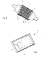
- FIG. 9 to 15 a second embodiment of a heat exchanger 100,200 comprising a beam 102,202 heat exchange (better visible on the figures 11 and 13 ) which is received in a distribution box 104,204.
- the beam 102 for heat exchange (better visible on the figure 12 ) allows the exchange of heat between a first fluid such as the charge air and a second fluid such as the coolant, in the example of a charge air cooler.
- This beam 102 is substantially similar to the beam 3 of the first embodiment and therefore comprises a stack of plates 11 as described above defining on the one hand first channels 13 for the circulation of the first fluid, and secondly second channels For the circulation of the second fluid.
- this beam 102 may comprise in the first channels 13 perturbation fins 16 and the plates 11 may have bosses 21 forming disrupter of the second fluid flowing in the second channels 15 and possibly longitudinal ribs 23 joining two plates 11 of a pair so as to define circulation passes 25a to 25d for the second fluid.
- the plates 11 also comprise respectively two inlet pipes 17 and outlet 19, for the passage of the second fluid; the tubings 17, 19 of a plate 11 communicating respectively with the tubings 17, 19 of a plate 11 of an adjacent pair to allow the circulation of the second fluid between the plates 11.
- the exchange beam 102 according to the second embodiment further comprises two end plates 106a, 106b closing two corresponding openings 108a, 108b of the distribution box 104.
- the beam 102 is therefore mounted in the distribution box 104 and not in a housing 5 as in the first embodiment, and the two end plates 106a, 106b of the beam 102 closes the openings 108a, 108b of the distribution box 104 forming a receiving box.
- one of the end plates 106b has inlet openings 27 and outlet 29 of water respectively communicating with the tubes 17,19 of the exchange beam 102 and with connecting pipes 110 and 112 associated with a water circuit in which the exchanger 100 is mounted.
- This housing 104 is here formed of a single piece which may be plastic and for example made by injection.
- this housing 104 has two opposite openings 108a, 108b closed by the beam 102 during mechanical assembly.
- the casing 104 is connected to ducts of an air circuit in which the exchanger 102 is mounted and thus has an inlet pipe 114 and an outlet pipe 116 thus allowing the circulation of air to flow. through the plates 11 opening into this housing 104.
- this housing 104 has two opposite edges 118a, 118b at the periphery of the openings 108a, 108b respectively cooperating with the end plates 106a, 106b for both the mechanical assembly and for sealing.
- this sealing means is arranged in a groove at the periphery of the openings 108a, 108b of the distribution box 104.
- a first groove for receiving the sealing means is formed by the peripheral rim 120 of one of the end plates 106b. Indeed, this flange 120 is folded so as to form a peripheral receiving groove 122 for the sealing means and the distribution box 104, more precisely for the peripheral edge 118b of the housing 104.
- the beam is arranged to so as to form at least one receiving groove of said sealing means.
- a second groove 123 for receiving the sealing means is formed at the opposite peripheral edge 118a of the dispensing box 104, in which the peripheral edge 124 of the end plate 106a is also arranged.
- the receiving grooves 122,123 serve both for the mechanical assembly of the beam 102 in the housing 104 and for sealing.
- the sealing means may be a seal formed advantageously of glue, especially epoxy glue or silicone to ensure the mechanical assembly and the seal between the beam 102 and the housing 104 .
- the beam 102 is thus glued to the housing 104 on two sides, here two long sides of the exchanger 100.
- the beam 102 contributes to the reinforcement of the housing 104.
- the exchange elements of the exchange bundle 102 such as the plates 11, and possibly the disturbing fins 16 and / or disruptive fins, are assembled together, for example by brazing.
- the beam 102 is arranged in the distribution box 104, for example by sliding, until the outer end plates 106a, 106b of the beam 102 respectively close the openings 108a, 108b of the housing 104. .
- a sealing material adhesive is then injected into the grooves of the reception provided for this purpose at the periphery of the openings 108a, 108b.
- This assembly results in a reduction of the internal volume subjected to the pressure.
- the beam 102 forms a supporting structure of the exchanger 100 contributing to the reinforcement of the housing 104.
- the seal is this time on three sides of the exchanger 200.
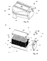
- the beam 202 (better visible on the figure 14 ) is substantially identical to the beam 102 illustrated on the figure 12 .
- the exchange elements identical to those described above are not described further.
- This beam 202 also comprises two end plates 206a, 206b closing two opposite openings 208a, 208b of the casing 204 but also comprises an outer lateral cover 210 for closing a third opening 212 of the casing 204 (cf. figure 15 ).
- This third opening 212 in this example on a small side of the exchanger 200, allows for example the insertion of the beam 202 in the housing 204.
- the end plates 206a, 206b of the beam 202 may have guide rails 213a, for example cooperating with guide grooves 213b, of the housing 204 when the beam 202 is inserted into the housing of distribution 204.
- the side cover 210 has two orifices 214,216 respectively communicating on the one hand with the orifices 27,29 provided on the outer plate 206b and on the other hand with the tubing 110,112 for connection to the water circuit in which the exchanger 200 is mounted. .
- This side cover 210 is in the illustrated example realized with a general shape substantially in polyhedron with side faces 210a substantially triangular.
- the side cover 210 also has holding means 218 on the housing 204.
- the side cover 210 is thus assembled facing a side wall 219 ( figure 14 ) of the beam 202 by closing the opening 212 of the housing 204.
- the plates 11 of the beam 202 open into the casing 204 connected to pipes of an air circuit in which the exchanger 202 is mounted and thus has an inlet pipe 220 and a pipe outlet 222 for the circulation of air through the plates 11.
- the housing 204 may as previously be made in one piece, this time having three openings 208a, 208b, 212.
- the distribution box 204 is formed by the assembly of two half-housings 204a and 204b.
- Each half-housing 204a, 204b has a substantially U-shaped cross-section.
- the first half-housing 204a comprises for example the opening 208a and optionally the two inlet pipes 218 and outlet 220 as in the example shown on two opposite sides of the half-housing 204a.
- the second half-housing 204b includes the opening 208b.
- Each half-housing 204a, 204b includes guide means 213b for guiding the beam 202 during assembly of the beam 202 and the housing 204.
- the two half-housings 204a, 204b can be assembled together by any appropriate means, as non-limiting examples by ultrasonic welding, friction, induction or by gluing.
- the beam 202 is the outer end plates 206a, 206b of the beam 202 that support the sealing means (not shown) arranged between the plates 206a, 206b and the distribution housing 204 at the periphery of the openings 208a, 208b of the distribution box 204.
- the beam is arranged to form at least one receiving groove of the sealing means;
- a seal is further provided between the lateral face of the beam facing the side cover 210 and this side cover 210.
- Sealing is thus provided here on three sides, here two long sides and a small side of the exchanger 200.
- the beam 202 contributes to the reinforcement of the housing 204.
- the exchange elements of the exchange beam 202 are assembled such as the plates 11, and possibly the disturbance fins 16 and / or disruptive together for example by brazing.
- the bundle 202 is arranged in the distribution box 204, for example by guiding the rails 213a of the external end plates 206a, 206b in the complementary grooves 213b of the casing 204, until the plates external end 206a, 206b of the beam 202 respectively close the openings 208a, 208b of the housing 204 or alternatively each half-housing 204a, 204b.
- a sealing material is then injected into the receiving grooves provided for this purpose at the periphery of the openings 208a, 208b, as well as between the side wall 219 of the beam 202 and the side cover 210.
- the exchanger 200 can then be brazed.
- this assembly causes a reduction in the internal volume subjected to pressure, and the beam 202 forms a supporting structure of the exchanger 200 by contributing to the reinforcement of the housing 204.
- a heat exchanger according to the embodiments described here are distinguished by a small footprint and ease of assembly while providing the necessary seal.
- the exchange beam forms a bearing structure of the exchanger and the exchanger has a volume less subject to mechanical stress.
Landscapes
- Engineering & Computer Science (AREA)
- Physics & Mathematics (AREA)
- Thermal Sciences (AREA)
- Mechanical Engineering (AREA)
- General Engineering & Computer Science (AREA)
- Heat-Exchange Devices With Radiators And Conduit Assemblies (AREA)
Applications Claiming Priority (1)
| Application Number | Priority Date | Filing Date | Title |
|---|---|---|---|
| FR1059209A FR2967245B1 (fr) | 2010-11-08 | 2010-11-08 | Echangeur de chaleur, notamment pour vehicule automobile, et procedes d'assemblage correspondants |
Publications (1)
| Publication Number | Publication Date |
|---|---|
| EP2450657A1 true EP2450657A1 (de) | 2012-05-09 |
Family
ID=44344307
Family Applications (1)
| Application Number | Title | Priority Date | Filing Date |
|---|---|---|---|
| EP11188042A Withdrawn EP2450657A1 (de) | 2010-11-08 | 2011-11-07 | Wärmetauscher, insbesondere für Kraftfahrzeug, und entsprechende Montageverfahren |
Country Status (2)
| Country | Link |
|---|---|
| EP (1) | EP2450657A1 (de) |
| FR (1) | FR2967245B1 (de) |
Cited By (7)
| Publication number | Priority date | Publication date | Assignee | Title |
|---|---|---|---|---|
| DE202011051713U1 (de) * | 2011-10-21 | 2013-01-23 | Autokühler GmbH & Co KG | Sammelkastenprofil |
| WO2014048962A1 (fr) * | 2012-09-28 | 2014-04-03 | Valeo Systemes Thermiques | Echangeur de chaleur |
| JP2018529924A (ja) * | 2016-01-11 | 2018-10-11 | ハンオン システムズ | 過給気冷却装置 |
| US10619946B2 (en) | 2015-02-23 | 2020-04-14 | Modine Manufacturing Company | Heat exchanger for cooling a flow of compressed air using a liquid coolant |
| EP3671097A1 (de) * | 2018-12-19 | 2020-06-24 | Valeo Autosystemy SP. Z.O.O. | Feststellsystem |
| CN111692899A (zh) * | 2019-08-28 | 2020-09-22 | 浙江三花智能控制股份有限公司 | 换热器及其制造方法 |
| JPWO2021176595A1 (de) * | 2020-03-04 | 2021-09-10 |
Citations (11)
| Publication number | Priority date | Publication date | Assignee | Title |
|---|---|---|---|---|
| DE19639422A1 (de) * | 1996-02-28 | 1997-09-04 | Man B & W Diesel Gmbh | Wasser-Luft-Wärmetauscher für Großmotoren |
| DE19902504A1 (de) * | 1999-01-22 | 2000-08-10 | Behr Gmbh & Co | Wärmeübertrager, insbesondere Ladeluftkühler |
| EP1707911A1 (de) * | 2005-03-19 | 2006-10-04 | Modine Manufacturing Company | Wärmetauscher, beispielsweise Ladeluftkühler und Herstellungsverfahren |
| DE102008018594A1 (de) * | 2007-04-11 | 2008-10-16 | Behr Gmbh & Co. Kg | Wärmetauscher |
| EP2014892A1 (de) * | 2007-07-11 | 2009-01-14 | João de Deus & Filhos, S.A. | Wärmetauscheranordnung |
| WO2010003807A1 (fr) * | 2008-06-26 | 2010-01-14 | Valeo Systemes Thermiques | Echangeur de chaleur et carter pour l'echangeur |
| US20100031507A1 (en) * | 2008-08-05 | 2010-02-11 | Suresh Deepchand Shah | Method for manifold manufacture and assembly |
| US20100096101A1 (en) * | 2006-08-18 | 2010-04-22 | Braun Jason J | Stacked/bar plate charge air cooler including inlet and outlet tanks |
| DE102009012024A1 (de) * | 2009-03-10 | 2010-09-16 | Behr Gmbh & Co. Kg | Ladeluftkühler zur Anordnung in einem Saugrohr |
| WO2011023516A1 (de) * | 2009-08-26 | 2011-03-03 | Behr Gmbh & Co. Kg | Gaskühler für einen verbrennungsmotor |
| WO2011073038A1 (fr) * | 2009-12-18 | 2011-06-23 | Valeo Systemes Thermiques | Echangeur de chaleur |
Family Cites Families (8)
| Publication number | Priority date | Publication date | Assignee | Title |
|---|---|---|---|---|
| DE3815070C2 (de) * | 1988-05-04 | 1996-10-17 | Laengerer & Reich Kuehler | Kühler, insbesondere Flüssigkeitskühler |
| DE29716257U1 (de) * | 1997-09-10 | 1997-11-06 | Behr Gmbh & Co, 70469 Stuttgart | Stapelscheiben-Wärmeübertrager |
| FR2855605B1 (fr) * | 2003-05-27 | 2007-03-23 | Valeo Thermique Moteur Sa | Echangeur de chaleur, en particulier refroidisseur d'air de suralimentation pour vehicules automobiles |
| FR2856747B1 (fr) * | 2003-06-25 | 2005-09-23 | Valeo Thermique Moteur Sa | Module de refroidissement de l'air de suralimentation et des gaz d'echappement recircules d'un moteur a combustion interne de vehicule automobile. |
| FR2869680B1 (fr) * | 2004-04-29 | 2006-07-28 | Valeo Thermique Moteur Sas | Echangeur de chaleur a plaques |
| FR2892802B1 (fr) * | 2005-10-28 | 2008-01-25 | Valeo Systemes Thermiques | Echangeur de chaleur muni d'une boite a fluide amelioree |
| DE102007058149A1 (de) * | 2006-11-30 | 2008-08-07 | Behr Gmbh & Co. Kg | Wärmetauscher, Anordnung und Verfahren zur Herstellung eines Wärmetauschers |
| FR2933175B1 (fr) * | 2008-06-26 | 2014-10-24 | Valeo Systemes Thermiques | Echangeur de chaleur comportant un faisceau d'echange de chaleur et un boitier |
-
2010
- 2010-11-08 FR FR1059209A patent/FR2967245B1/fr not_active Expired - Fee Related
-
2011
- 2011-11-07 EP EP11188042A patent/EP2450657A1/de not_active Withdrawn
Patent Citations (11)
| Publication number | Priority date | Publication date | Assignee | Title |
|---|---|---|---|---|
| DE19639422A1 (de) * | 1996-02-28 | 1997-09-04 | Man B & W Diesel Gmbh | Wasser-Luft-Wärmetauscher für Großmotoren |
| DE19902504A1 (de) * | 1999-01-22 | 2000-08-10 | Behr Gmbh & Co | Wärmeübertrager, insbesondere Ladeluftkühler |
| EP1707911A1 (de) * | 2005-03-19 | 2006-10-04 | Modine Manufacturing Company | Wärmetauscher, beispielsweise Ladeluftkühler und Herstellungsverfahren |
| US20100096101A1 (en) * | 2006-08-18 | 2010-04-22 | Braun Jason J | Stacked/bar plate charge air cooler including inlet and outlet tanks |
| DE102008018594A1 (de) * | 2007-04-11 | 2008-10-16 | Behr Gmbh & Co. Kg | Wärmetauscher |
| EP2014892A1 (de) * | 2007-07-11 | 2009-01-14 | João de Deus & Filhos, S.A. | Wärmetauscheranordnung |
| WO2010003807A1 (fr) * | 2008-06-26 | 2010-01-14 | Valeo Systemes Thermiques | Echangeur de chaleur et carter pour l'echangeur |
| US20100031507A1 (en) * | 2008-08-05 | 2010-02-11 | Suresh Deepchand Shah | Method for manifold manufacture and assembly |
| DE102009012024A1 (de) * | 2009-03-10 | 2010-09-16 | Behr Gmbh & Co. Kg | Ladeluftkühler zur Anordnung in einem Saugrohr |
| WO2011023516A1 (de) * | 2009-08-26 | 2011-03-03 | Behr Gmbh & Co. Kg | Gaskühler für einen verbrennungsmotor |
| WO2011073038A1 (fr) * | 2009-12-18 | 2011-06-23 | Valeo Systemes Thermiques | Echangeur de chaleur |
Cited By (16)
| Publication number | Priority date | Publication date | Assignee | Title |
|---|---|---|---|---|
| DE202011051713U1 (de) * | 2011-10-21 | 2013-01-23 | Autokühler GmbH & Co KG | Sammelkastenprofil |
| EP2901095B2 (de) † | 2012-09-28 | 2020-05-27 | Valeo Systemes Thermiques | Wärmetauscher |
| EP2901095B1 (de) | 2012-09-28 | 2016-09-14 | Valeo Systemes Thermiques | Wärmetauscher |
| CN104838223B (zh) * | 2012-09-28 | 2017-03-08 | 法雷奥热系统公司 | 热交换器 |
| WO2014048962A1 (fr) * | 2012-09-28 | 2014-04-03 | Valeo Systemes Thermiques | Echangeur de chaleur |
| US10323886B2 (en) | 2012-09-28 | 2019-06-18 | Valeo Systemes Thermiques | Heat exchanger |
| FR2996298A1 (fr) * | 2012-09-28 | 2014-04-04 | Valeo Systemes Thermiques | Echangeur de chaleur |
| US10619946B2 (en) | 2015-02-23 | 2020-04-14 | Modine Manufacturing Company | Heat exchanger for cooling a flow of compressed air using a liquid coolant |
| JP2018529924A (ja) * | 2016-01-11 | 2018-10-11 | ハンオン システムズ | 過給気冷却装置 |
| WO2020127721A1 (en) * | 2018-12-19 | 2020-06-25 | Valeo Autosystemy Sp. Z O.O. | An arresting system |
| EP3671097A1 (de) * | 2018-12-19 | 2020-06-24 | Valeo Autosystemy SP. Z.O.O. | Feststellsystem |
| CN111692899A (zh) * | 2019-08-28 | 2020-09-22 | 浙江三花智能控制股份有限公司 | 换热器及其制造方法 |
| CN111692899B (zh) * | 2019-08-28 | 2022-05-13 | 浙江三花智能控制股份有限公司 | 换热器及其制造方法 |
| JPWO2021176595A1 (de) * | 2020-03-04 | 2021-09-10 | ||
| WO2021176595A1 (ja) * | 2020-03-04 | 2021-09-10 | 三菱電機株式会社 | 熱交換器ユニットおよび室外機 |
| JP7241959B2 (ja) | 2020-03-04 | 2023-03-17 | 三菱電機株式会社 | 熱交換器ユニットおよび室外機 |
Also Published As
| Publication number | Publication date |
|---|---|
| FR2967245A1 (fr) | 2012-05-11 |
| FR2967245B1 (fr) | 2014-11-28 |
Similar Documents
| Publication | Publication Date | Title |
|---|---|---|
| EP1646780B1 (de) | Modul zum kühlen von ladeluft und rückgeführten abgasen vom verbrennungsmotor eines kraftfahrzeugs | |
| EP2064506B1 (de) | Wärmetauscher, insbesondere ein systemluftkühler | |
| EP2450657A1 (de) | Wärmetauscher, insbesondere für Kraftfahrzeug, und entsprechende Montageverfahren | |
| EP2726804B1 (de) | Wärmetauscher, insbesondere für ein kraftfahrzeug | |
| EP2972049B1 (de) | Wärmetauscher, insbesondere supraladender luftkühler | |
| EP2726806A1 (de) | Gestapelter plattenwärmetauschergehäuse und wärmetauscher mit einem solchen gehäuse | |
| FR2954482A1 (fr) | Echangeur de chaleur | |
| WO2011073038A1 (fr) | Echangeur de chaleur | |
| FR2949554A1 (fr) | Echangeur thermique | |
| FR2855605A1 (fr) | Echangeur de chaleur, en particulier refroidisseur d'air de suralimentation pour vehicules automobiles | |
| EP2912396B1 (de) | Wärmetauscher, insbesondere für ein kraftfahrzeug | |
| FR2968753A1 (fr) | Echangeur de chaleur, notamment pour vehicule automobile | |
| FR2855604A1 (fr) | Echangeur de chaleur a plaques comportant un element d'obturation des fuites du gaz a fefroidir. | |
| EP1886086A1 (de) | Wärmetauscher mit in ein gehäuse eingepasstem wärmetauschbündel | |
| FR2947045A1 (fr) | Bloc d'echangeur de chaleur, en particulier pour condenseur de climatisation | |
| FR2936043A1 (fr) | Echangeur de chaleur a tubes | |
| WO2004106834A2 (fr) | Echangeur de chaleur a plaques, notamment refroidisseur des gaz d’echappement recircules | |
| WO2003081159A1 (fr) | Echangeur de chaleur, notamment pour un vehicule automobile, constitue d'elements tubulaires empiles | |
| FR2935912A1 (fr) | Procede d'assemblage et de brasage de deux pieces munies d'elements d'assemblage. | |
| FR3030709A1 (fr) | Echangeur de chaleur | |
| FR2996295A1 (fr) | Echangeur de chaleur, notamment pour vehicule automobile, et procede d'assemblage associe. | |
| EP1548385A2 (de) | Wärmetauscherrohr mit zwei Strömungskanälen und Wärmetauscher mit solchen Rohren | |
| FR2855603A1 (fr) | Echangeur de chaleur a plaques, notamment refroidisseur des gaz d'echappement recircules, comportant une enveloppe delimitant des boites d'entree et de sortie de ces gaz | |
| FR2997486A1 (fr) | Tube d'echangeur de chaleur a moyen de perturbation plat | |
| EP2463610A1 (de) | Wärmetauscher, insbesondere für Kraftfahrzeug |
Legal Events
| Date | Code | Title | Description |
|---|---|---|---|
| PUAI | Public reference made under article 153(3) epc to a published international application that has entered the european phase |
Free format text: ORIGINAL CODE: 0009012 |
|
| AK | Designated contracting states |
Kind code of ref document: A1 Designated state(s): AL AT BE BG CH CY CZ DE DK EE ES FI FR GB GR HR HU IE IS IT LI LT LU LV MC MK MT NL NO PL PT RO RS SE SI SK SM TR |
|
| AX | Request for extension of the european patent |
Extension state: BA ME |
|
| 17P | Request for examination filed |
Effective date: 20130118 |
|
| STAA | Information on the status of an ep patent application or granted ep patent |
Free format text: STATUS: EXAMINATION IS IN PROGRESS |
|
| 17Q | First examination report despatched |
Effective date: 20170407 |
|
| STAA | Information on the status of an ep patent application or granted ep patent |
Free format text: STATUS: THE APPLICATION IS DEEMED TO BE WITHDRAWN |
|
| 18D | Application deemed to be withdrawn |
Effective date: 20180602 |