EP2451343B1 - System zur ansicht des nadeleintritts in einen körper - Google Patents
System zur ansicht des nadeleintritts in einen körper Download PDFInfo
- Publication number
- EP2451343B1 EP2451343B1 EP10731697.8A EP10731697A EP2451343B1 EP 2451343 B1 EP2451343 B1 EP 2451343B1 EP 10731697 A EP10731697 A EP 10731697A EP 2451343 B1 EP2451343 B1 EP 2451343B1
- Authority
- EP
- European Patent Office
- Prior art keywords
- needle
- coating
- radiation
- coated
- blood
- Prior art date
- Legal status (The legal status is an assumption and is not a legal conclusion. Google has not performed a legal analysis and makes no representation as to the accuracy of the status listed.)
- Active
Links
- 0 CC(CCCN)C(C)CC*CC* Chemical compound CC(CCCN)C(C)CC*CC* 0.000 description 1
- GQDYKYGFCJNFOU-UHFFFAOYSA-N CCCCC1NC1 Chemical compound CCCCC1NC1 GQDYKYGFCJNFOU-UHFFFAOYSA-N 0.000 description 1
Images

Classifications
-
- A—HUMAN NECESSITIES
- A61—MEDICAL OR VETERINARY SCIENCE; HYGIENE
- A61B—DIAGNOSIS; SURGERY; IDENTIFICATION
- A61B5/00—Measuring for diagnostic purposes; Identification of persons
- A61B5/0059—Measuring for diagnostic purposes; Identification of persons using light, e.g. diagnosis by transillumination, diascopy, fluorescence
-
- A—HUMAN NECESSITIES
- A61—MEDICAL OR VETERINARY SCIENCE; HYGIENE
- A61B—DIAGNOSIS; SURGERY; IDENTIFICATION
- A61B5/00—Measuring for diagnostic purposes; Identification of persons
- A61B5/15—Devices for taking samples of blood
- A61B5/150007—Details
- A61B5/150015—Source of blood
- A61B5/15003—Source of blood for venous or arterial blood
-
- A—HUMAN NECESSITIES
- A61—MEDICAL OR VETERINARY SCIENCE; HYGIENE
- A61B—DIAGNOSIS; SURGERY; IDENTIFICATION
- A61B5/00—Measuring for diagnostic purposes; Identification of persons
- A61B5/15—Devices for taking samples of blood
- A61B5/150007—Details
- A61B5/150374—Details of piercing elements or protective means for preventing accidental injuries by such piercing elements
- A61B5/150381—Design of piercing elements
- A61B5/150389—Hollow piercing elements, e.g. canulas, needles, for piercing the skin
-
- A—HUMAN NECESSITIES
- A61—MEDICAL OR VETERINARY SCIENCE; HYGIENE
- A61B—DIAGNOSIS; SURGERY; IDENTIFICATION
- A61B5/00—Measuring for diagnostic purposes; Identification of persons
- A61B5/15—Devices for taking samples of blood
- A61B5/150007—Details
- A61B5/150374—Details of piercing elements or protective means for preventing accidental injuries by such piercing elements
- A61B5/150381—Design of piercing elements
- A61B5/150503—Single-ended needles
- A61B5/150511—Details of construction of shaft
-
- A—HUMAN NECESSITIES
- A61—MEDICAL OR VETERINARY SCIENCE; HYGIENE
- A61B—DIAGNOSIS; SURGERY; IDENTIFICATION
- A61B5/00—Measuring for diagnostic purposes; Identification of persons
- A61B5/15—Devices for taking samples of blood
- A61B5/150007—Details
- A61B5/150374—Details of piercing elements or protective means for preventing accidental injuries by such piercing elements
- A61B5/150381—Design of piercing elements
- A61B5/150503—Single-ended needles
- A61B5/150519—Details of construction of hub, i.e. element used to attach the single-ended needle to a piercing device or sampling device
-
- A—HUMAN NECESSITIES
- A61—MEDICAL OR VETERINARY SCIENCE; HYGIENE
- A61B—DIAGNOSIS; SURGERY; IDENTIFICATION
- A61B5/00—Measuring for diagnostic purposes; Identification of persons
- A61B5/15—Devices for taking samples of blood
- A61B5/150007—Details
- A61B5/150748—Having means for aiding positioning of the piercing device at a location where the body is to be pierced
-
- A—HUMAN NECESSITIES
- A61—MEDICAL OR VETERINARY SCIENCE; HYGIENE
- A61B—DIAGNOSIS; SURGERY; IDENTIFICATION
- A61B5/00—Measuring for diagnostic purposes; Identification of persons
- A61B5/15—Devices for taking samples of blood
- A61B5/153—Devices specially adapted for taking samples of venous or arterial blood, e.g. with syringes
- A61B5/1535—Devices specially adapted for taking samples of venous or arterial blood, e.g. with syringes comprising means for indicating vein or arterial entry
-
- A—HUMAN NECESSITIES
- A61—MEDICAL OR VETERINARY SCIENCE; HYGIENE
- A61B—DIAGNOSIS; SURGERY; IDENTIFICATION
- A61B5/00—Measuring for diagnostic purposes; Identification of persons
- A61B5/48—Other medical applications
- A61B5/4887—Locating particular structures in or on the body
- A61B5/489—Blood vessels
-
- A—HUMAN NECESSITIES
- A61—MEDICAL OR VETERINARY SCIENCE; HYGIENE
- A61B—DIAGNOSIS; SURGERY; IDENTIFICATION
- A61B90/00—Instruments, implements or accessories specially adapted for surgery or diagnosis and not covered by any of the groups A61B1/00 - A61B50/00, e.g. for luxation treatment or for protecting wound edges
- A61B90/36—Image-producing devices or illumination devices not otherwise provided for
- A61B90/37—Surgical systems with images on a monitor during operation
-
- A—HUMAN NECESSITIES
- A61—MEDICAL OR VETERINARY SCIENCE; HYGIENE
- A61B—DIAGNOSIS; SURGERY; IDENTIFICATION
- A61B17/00—Surgical instruments, devices or methods
- A61B17/34—Trocars; Puncturing needles
- A61B17/3403—Needle locating or guiding means
-
- A—HUMAN NECESSITIES
- A61—MEDICAL OR VETERINARY SCIENCE; HYGIENE
- A61B—DIAGNOSIS; SURGERY; IDENTIFICATION
- A61B90/00—Instruments, implements or accessories specially adapted for surgery or diagnosis and not covered by any of the groups A61B1/00 - A61B50/00, e.g. for luxation treatment or for protecting wound edges
- A61B90/39—Markers, e.g. radio-opaque or breast lesions markers
- A61B2090/3937—Visible markers
- A61B2090/3941—Photoluminescent markers
-
- A—HUMAN NECESSITIES
- A61—MEDICAL OR VETERINARY SCIENCE; HYGIENE
- A61B—DIAGNOSIS; SURGERY; IDENTIFICATION
- A61B90/00—Instruments, implements or accessories specially adapted for surgery or diagnosis and not covered by any of the groups A61B1/00 - A61B50/00, e.g. for luxation treatment or for protecting wound edges
- A61B90/50—Supports for surgical instruments, e.g. articulated arms
- A61B2090/502—Headgear, e.g. helmet, spectacles
-
- A—HUMAN NECESSITIES
- A61—MEDICAL OR VETERINARY SCIENCE; HYGIENE
- A61B—DIAGNOSIS; SURGERY; IDENTIFICATION
- A61B5/00—Measuring for diagnostic purposes; Identification of persons
- A61B5/15—Devices for taking samples of blood
- A61B5/150007—Details
- A61B5/150206—Construction or design features not otherwise provided for; manufacturing or production; packages; sterilisation of piercing element, piercing device or sampling device
- A61B5/150267—Modular design or construction, i.e. subunits are assembled separately before being joined together or the device comprises interchangeable or detachable modules
-
- A—HUMAN NECESSITIES
- A61—MEDICAL OR VETERINARY SCIENCE; HYGIENE
- A61B—DIAGNOSIS; SURGERY; IDENTIFICATION
- A61B5/00—Measuring for diagnostic purposes; Identification of persons
- A61B5/15—Devices for taking samples of blood
- A61B5/155—Devices specially adapted for continuous or multiple sampling, e.g. at predetermined intervals
-
- A—HUMAN NECESSITIES
- A61—MEDICAL OR VETERINARY SCIENCE; HYGIENE
- A61B—DIAGNOSIS; SURGERY; IDENTIFICATION
- A61B90/00—Instruments, implements or accessories specially adapted for surgery or diagnosis and not covered by any of the groups A61B1/00 - A61B50/00, e.g. for luxation treatment or for protecting wound edges
- A61B90/36—Image-producing devices or illumination devices not otherwise provided for
- A61B90/361—Image-producing devices, e.g. surgical cameras
Definitions
- the present invention relates to a system for visualizing a needle within biological tissue. More particularly, the invention relates to a system for visualizing a needle and locating anatomical structures within a body by utilizing equipment sensitive to the unique absorption and scattering characteristics of the target structures.
- Venipuncture is required in order to administer emergency fluids, blood components, and anesthetics during operations, or to allow the drawing of blood for biochemical analysis. Venipuncture, which is often the rate-limiting step when administering intravenous compounds, can take as long as a half hour, or longer when the patient is a neonate, infant, geriatric, obese, or burn patient. Notwithstanding the enormous financial burden on our society as a whole because operating rooms and health-care providers must wait as an intravenous line is placed, the delay in placing an intravenous line can in fact be life threatening. Furthermore, there are additional problems associated with multiple venipunctures caused by the clinician's failure to locate the vessel.
- venipuncture is sometimes difficult to do is that the blood vessels are often located relatively deep within the tissue which, because of its absorptive and scattering optical properties, makes visualization of the blood vessel impossible under normal conditions. Furthermore, the situation is made worse by the fact that the vessel may spasm and constrict if it is manipulated too much. Consequently, health care providers have a need to visualize blood vessels in real-time during venipuncture in order to reduce the risk to the patient, save time and reduce the cost of the procedure. Furthermore, reducing the time of the procedure limits the providers' exposure to a potentially contaminated needle. Finally, visualization of vascular tissue can provide important diagnostic and therapeutic information about certain diseases such as thromboses, cancers or vascular malformations.
- an instrument was devised that purportedly provided surgeons with the ability of visualizing superficial blood vessels. It consisted of a visible light source which, when pressed up against the skin, transilluminated the subcutaneous tissue and aided in the visualization of superficial blood vessels.
- the blood-vessel transilluminator made use of the different absorption properties of blood and tissue. Because blood strongly absorbs certain wavelengths of light, while fat and skin absorb other wavelengths, a health-care provider purportedly could visually distinguish the position of the subcutaneous blood vessel with the naked eye.
- the transilluminator has essentially fallen into disuse because it fails to provide enough contrast between the blood vessel and tissue to be of use other than for venipuncture of superficial vessels. Furthermore, some versions of the blood-vessel transilluminator caused thermal damage to the patient.
- US 2008/0194930 A1 discloses an imaging apparatus with a light source that emits at least light having one or more wavelengths in the range of about 70 nm to about 2500 nm, a camera that is (a) sensitive to light having a wavelength in the range of about 700 nm to about 2500 nm, and (b) so positioned relative to the light source as to receive light having a wavelength in this range that has been (i) emitted from the light source and (ii) reflected from a target.
- WO 2009/021064 A1 discloses medical apparatuses incorporating dyes to facilitate proper positioning in patients.
- the apparatuses can be tubes, catheters or needles.
- the dye can be a near infrared fluorescent dye.
- WO 2006/073869 A2 discloses a needle insertion system which includes an imaging system and a needle.
- the imaging system includes at least an infrared emitter, an infrared detector, a computing unit, a display device and a power source
- a system for visualizing needle entry into a body that includes a needle, a radiation scattering coating (herein occasionally referred to simply as a “coating” or a “needle coating”), and a radiation visualization device.
- the radiation scattering coating may be a near infrared radiation scattering coating or an infrared radiation scattering coating.
- the needle coating is coated on at least a portion of the needle.
- the coating may include one or more polymers.
- the coating may include fluorinated ethylene propylene (FEP) or polytetrafluoroethylene (PTFE).
- FEP fluorinated ethylene propylene
- PTFE polytetrafluoroethylene
- the coating may include at least one of a pigment and a dye that scatters incident near infrared radiation.
- the coating may include a saturating feature, such as a channel, a groove, or a pore.
- the coating may be coated only on the needle tip. Alternatively, the coating may be coated the entire needle except the needle tip.
- the coating may coat the needle using a pattern of coated and uncoated portions.
- the radiation visualization device may include a detector that visualizes based on tomography, spectroscopy, or spectral imaging.
- a system for visualizing needle entry into a body includes a needle, a radiation scattering coating coated on the needle, the coating including at least one of fluorinated ethylene propylene (FEP) and polytetrafluoroethylene (PTFE), the coating further including at least one of a radiation scattering pigment and a radiation scattering dye, and a radiation visualization device.
- FEP fluorinated ethylene propylene
- PTFE polytetrafluoroethylene
- implementations of the present systems enable a medical clinician to visualize not only internal anatomical structures, but also a needle as it is advanced into a body.
- clinicians are enabled to visualize internal structures, venipuncture procedures may be performed more rapidly and accurately.
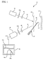
- Figure 1 illustrates a system for visualizing needle entry into a body.
- the system includes a radiation visualization device or system 20 (e.g. Digital VeinVue from VueTek Scientific) which includes a radiation light source 30, a radiation detector 36, and a display 38.
- the radiation is infrared (IR) radiation
- the radiation is near infrared radiation (NIR).
- IR infrared
- NIR near infrared radiation
- the light source 30 radiates a beam of incident light 32 upon a biological tissue 40, such that the beam is partially transmitted through the biological tissue until being absorbed by the target anatomical structure 42.
- An image detector 36 (e.g.
- Model CCD-72 camera available from Dage-MTI, Inc. detects reflected light 34, predominantly reflected from tissue surrounding the target anatomical structure with a different absorptive wavelength than the anatomical structure.
- the image detector 36 is connected by a video signal 44 to the monitor 38 so that the intensity information of incident light reflected from the tissue is displayed onto the monitor in the form of an image.
- a needle 22 may be inserted into the biological tissue 40 and be directed towards the target anatomical structure 42.
- the radiation scattering coating 26 (herein occasionally referred to simply as a "coating” or a “needle coating”) that is coated on the needle 22.
- light 32 incident upon the uncoated portions of the needle 22 is absorbed in a greater degree than that incident upon the coating 26. Accordingly, more light 34 is reflected from the coated portions 26 of the needle 22 than from the uncoated portions. The reflected light 34 is detected by the detector 36 and imaged by the monitor 38.
- the monitor will thus image the shape of the target anatomical structure 42 and the coated portion of the needle 22. In this manner, the medical personnel can direct the needle tip 24 into the target anatomical structure 42.
- the needle coating 26 is a radiation scattering coating.
- the needle coating 26 is a radiation absorbing coating, wherein the needle coating is distinguished from the more opaque background or target anatomical structure.
- a radiation scattering coating can assist medical personnel during various medical procedures. Accordingly, the radiation scattering coating can be applied to various needle types.
- the needle is a hypodermic needle.
- the needle is an introducer needle used in over the needle catheter placement procedures.
- the radiation scattering coating is applied to a catheter, used with an introducer needle.
- the radiation scattering coating is coated onto a rigid catheter.
- needle will include standard needles, such as hypodermic needles, as wells as catheters and other like devices that may be used to access an anatomical structure near the outer surface of a body and/or deliver a fluid thereto.
- the coating is a polymer or copolymer.
- the coating includes fluorinated ethylene propylene (FEP) that is applied to the needle view melt extrusion, coating, or impregnation (e.g. Neoflon® from Daikin, and Hostaflon® from Hoechst).
- FEP fluorinated ethylene propylene
- the coating includes polytetrafluoroethylene (PTFE) (e.g. Teflon®FEP from Dupont). Since FEP has may be highly transparent it can be coated onto a needle without being noticeable or distracting to patients or medical personnel.
- the needle 22 or the needle coating 26 includes a pigment or a dye that scatters incident near infrared radiation.
- ICG indocyanine-green
- the needle 22 or the needle coating 26 includes a pigment or a dye that scatters incident near infrared radiation.
- ICG indocyanine-green
- an ICG dye disposed with a needle coating or coated on a needle may reflect 800 nm illumination.
- other NIR/IR-opaque or NIR/IR-reflective substances are applied to the needle 22 or needle coating 26.
- the needle coating 26 can be applied to the entire needle 22, the needle tip 24 (shown in Figures 1-2 and 4 ), or the entire needle minus the needle tip (shown in Figure 5 ). Additionally, in some embodiments, a pattern of needle coating 26 is applied to the needle 22 as alternating coated and uncoated regions, as shown in Figure 6 .
- NIR radiation enables medical personnel to detect signal reflection through as much as twelve centimeters of body tissue.
- the location of the vessel or vein in relation to the needle tip 24 is critical to proper needle placement. Absent a needle coating, the needle directs the majority of incident light away from the detector 36. This effect makes it difficult to determine when the needle has entered the vein because the vein also appears black in the display 38. Accordingly, the needle tip may be coated or uncoated so as to provide a distinct image of the needle tip during imaging, based on the nature of the coating.
- the display 38 depicts the blood vessel 42a as darker than the surrounding tissue.
- a clinician visualizes the location of the blood vessel 42a.
- the properties of the needle coating cause the coating to be displayed as darker in the display.
- the clinician can direct a darker, coated needle tip into the blood vessel accurately and quickly.
- the properties of the needle coating lead it to be displayed as a lighter object, and in this situation a coated tip will be displayed as the lighter object that can disappear into the darker blood vessel in ensure proper needle tip 24 placement. Accordingly, the needle coating enables medical personnel to more effectively introduce a needle into a body.
- the needle 22 and needle coating 26 can be utilized with a variety of radiation visualization systems.
- the radiation visualization system 20 of Figure 1 illustrates just one of several possible embodiments of a radiation visualization systems or devices that may be utilized with the present needle and needle coatings.
- An image detector 36 e.g. Model CCD-72 camera available from Dage-MTI, Inc.
- detects reflected light 34 predominantly reflected from tissue surrounding the target anatomical structure with a different absorptive wavelength than the anatomical structure.
- the image detector 36 is connected by a video signal 44 to the monitor 38 so that the intensity information of incident light reflected from the tissue is displayed onto the monitor in the form of an image.
- a polychromatic light source e.g., a polychromatic light source
- wavelengths outside the useful range for imaging the target structure should be filtered out by one or more bandpass filters 48.
- the imaging detector can detect only wavelengths within the useful range, such as occurs with a charge-coupled device infrared camera (CCD) (e.g. CCD1350-1 infrared CCD camera and 9300-00 image intensifier available from Electrophysics Corp. Fairfield N.J.).
- CCD charge-coupled device infrared camera
- a real-time digital image processor e.g. CSP-2000 Processor available from Dage-MTI Inc.
- CSP-2000 Processor available from Dage-MTI Inc.
- a polarizing optical element 46a such as a polarizing filter (e.g. available from Ealing Electro-Optics Ind., Holliston, Mass. or Oriel Corp., Stratford, Conn.) is used in combination with a laser or other monochromatic light source.
- Monochromatic sources include, by way of example, the Model 6124 laser diode available from New Focus, Inc. Sunnyvale Calif., the Model Micralase available from Micracor, Inc., Acton Mass., and the MDL-DLAW10 available from McDonnell Douglas Aerospace, St. Louis Mo.
- the polarizing filter by polarizing the incident light in a particular plane with respect to the tissue will cause the singularly reflected light to be of a distinct polarization.
- a second polarizing optical element 46b in front of the detector then preferentially selects out singularly reflected radiation from the light source.
- Multiply scattered radiation which carries little image information, is typically randomly polarized and thus will not pass through the second polarizing optical element 46b and onto the image detector 12.
- the polarizing filters can be used with either the bandpass filter 48, the charge-coupled device infrared camera or any combination of these in the event a polychromatic light source is used for the light source 30. Any combination of these elements may also be used when the light source 30 comprises a laser or other monochromatic light source.
- the system incorporates other imaging systems for imaging the internal anatomical structures of a body.
- the imaging system utilizes a digital image processor, a frame grabber (such as the CSP-2000 processor available from Dage-MTI Inc.), and a light source that projects at least two wavelengths.
- the imaging system utilizes collimators to eliminate scattered light.
- the imaging system performs phase-modulated detection of the reflected image 34.
- incident laser light 34 is phase modulated by a modulation source 30 which controls a light phase modulator 28 such as a rotating aspheric optic or a Kerr cell (e.g. available from Meadowlark Optics, Longmont Colo., Advanced Optronics Inc., San Jose Calif., or Ninds Instruments Inc., Nillsboro Oreg.)
- the modulation source controls the phase-sensitive imaging detector such as a liquid crystal video television.
- the image detector only measures the reflected light that has the same state of modulation as the incident light. All other light is removed from the measurement.
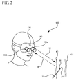
- the imaging system 100 utilizes binocular stereo imaging of a target anatomical structure.
- three dimensional depth information is incorporated within the image by detecting two angles of reflected light from the target tissue area using two imaging detectors 136a and 136b (e.g. Model 8900 infrared sensitive video cameras with focusing eyepieces and objective lenses from FJW Optical Systems Inc., Palatine, I11.)
- a light source 130 e.g. MDL-DLAW10 diode laser from McDonnell Douglas Aerospace, St. Louis, Mo., with LD1001 driver from Thor-Labs, Newton N.J. and 12 V DC source
- a helmet e.g.
- the Physician's Headlight from Welch-Allyn Inc., Skaeneateles Falls, N.Y. which in turn holds the two imaging detectors 136a and 136b.
- the light source output may optionally be focused with diode laser collimation optics (e.g. Model LT110P-B from Thor-Labs, Newton, N.J.) to produce about a 1 mm spot at a distance of about 20 inches.
- the incident light 32 is reflected back from the target tissue as 34. Variations of the binocular stereo imaging system may be incorporated into the present systems and methods.
- the needle includes a needle hub 202 disposed at the proximal end of the needle 22.
- a needle shaft 206 extends from the distal end of the needle hub 202.
- a beveled needle tip 208 is formed in the distal end of the needle to facilitate entry into a body.
- the needle also includes a distal portion 24 which is approximately two to three times the distance of the needle tip.
- the needle coating 210 is coated only on the needle tip 208, as shown in Figure 4 , or only on the distal portion 24 of the needle. Alternatively, in some embodiments, the needle coating 210 is coated on the entire needle shaft 206 minus the needle tip 208, as shown in Figure 5 . In other embodiments, the needle coating 210 is coated either on the shaft 206, the needle tip 208, or the distal end 24 using a pattern of coated and uncoated portions, as shown in Figure 6 .
- the needle further includes an interior lumen 204 that extends through the needle from the distal to the proximal end.
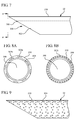
- a needle 22 is depicted as having a needle coating 210.
- One or more saturating features 302 may be included within the needle coating 210.
- a saturating feature enables blood to fill up, wick, or otherwise saturate the needle coating 210 in order to defeat the scattering properties of the coating.
- blood absorbs or scatters radiation differently than the needle coating 210, accordingly, when blood saturates the coating, which may be transparent, radiation incident on the saturated coating responds the same or substantially the same as a blood vessel.
- the saturation of the needle coating 210 can be watched to ensure that the blood vessel is properly accessed.
- the saturation feature 302 When used with needles having a flashback feature, the saturation feature 302 enables medical personnel to visualize flashback along the needle before it is directly visible without a radiation visualization device.
- medical personnel can visualize entry of the needle tip into a target anatomical structure, such as a blood vessel.
- a target anatomical structure such as a blood vessel.
- the medical personnel still using the radiation visualization device, can see the flashback as the blood defeats the needle coating 210. Since blood may be displayed as darker than the coating, as it saturates the saturation feature(s) 302 by making the coating appear darker.
- Such features enable medical personnel to conduct the entire needle insertion process using the radiation visualization device/system rather than watching both the display and the needle insertion site.
- the saturation feature is one or more of a channel, pore, groove, or other like feature within the needle coating.
- the needle coating includes one or more saturation features that extend down the length of the needle 22.
- Figures 8A and 8B illustrate front views of a distal end of a needle taken along line 8 of Figure 7 .
- the needle shaft 206 includes an internal lumen 306 and an external needle coating 210.
- the coating includes one or more saturation features 302a and 302b in the form of channels or grooves that extend at least partially into the needle coating and along the length of the needle.
- the saturation features 302a are disposed on the exterior of the needle coating.
- the saturation features 302b are disposed on the interior of the needle coating. Additionally, in some embodiments, the saturation features 302c are disposed throughout the needle coating, as shown Figure 8B . Blood may flow along or through the saturation features 302a-302c or be wicked therein.
- Figure 9 depicts a needle coating 210 on a needle 22.
- the needle coating 210 includes a plurality of pores 304 which function as saturation features. As blood comes in contact with the needle coating it is drawn therein via wicking or other means. Once within the needle coating, the blood defeats the needle coating and enables a medical practitioner to recognize that blood has been saturated within the needle coating. Accordingly, the saturation features enable flashback to be recognized along the needle that is disposed within a body, prior to the flashback being visible exterior to the body.
- embodiments of the present systems enable a medical clinician to visualize not only internal anatomical structures, but also a needle as it is advanced into a body.
- the application of a radiation scattering coating on a needle enables clinicians to visualize internal structures of a body.
- the enhanced visualization may enable venipuncture procedures to be performed more rapidly and accurately that possible in the absence of a needle with a radiation scattering coating.
Landscapes
- Health & Medical Sciences (AREA)
- Life Sciences & Earth Sciences (AREA)
- Surgery (AREA)
- Animal Behavior & Ethology (AREA)
- Public Health (AREA)
- Pathology (AREA)
- Engineering & Computer Science (AREA)
- Biomedical Technology (AREA)
- Heart & Thoracic Surgery (AREA)
- Medical Informatics (AREA)
- Molecular Biology (AREA)
- Veterinary Medicine (AREA)
- General Health & Medical Sciences (AREA)
- Biophysics (AREA)
- Physics & Mathematics (AREA)
- Hematology (AREA)
- Vascular Medicine (AREA)
- Nuclear Medicine, Radiotherapy & Molecular Imaging (AREA)
- Gynecology & Obstetrics (AREA)
- Radiology & Medical Imaging (AREA)
- Oral & Maxillofacial Surgery (AREA)
- Infusion, Injection, And Reservoir Apparatuses (AREA)
- Investigating Or Analysing Materials By Optical Means (AREA)
- Measurement Of The Respiration, Hearing Ability, Form, And Blood Characteristics Of Living Organisms (AREA)
Claims (10)
- System zur Visualisierung des Nadeleintritts in einen Körper, mit:einer Nadel (22);einer Strahlungsstreubeschichtung, mit welcher die Nadel (22) beschichtet ist; undeiner Strahlungsvisualisierungsvorrichtung (20),dadurch gekennzeichnet, dass
die Strahlungsstreubeschichtung (210) mehrere Poren (304) aufweist, welche es einem Arzt ermöglicht, zu erkennen, dass Blut in der Nadelbeschichtung gesättigt wurde, während Blut in Kontakt mit der Nadelbeschichtung kommt. - System nach Anspruch 1, bei welcher die Beschichtung mindestens ein Polymer enthält.
- System nach Anspruch 1, bei welcher die Beschichtung Fluorethylenpropylen (FEP) und/oder Polytetrafluorethylen (PTFE) und/oder Kombinationen derselben aufweist.
- System nach Anspruch 1, bei welcher die Beschichtung ein Pigment und/oder einen Farbstoff aufweist, das/der einfallende Nahinfrarotstrahlung streut.
- System nach Anspruch 1, bei welcher die Beschichtung auf der Nadelspitze (24, 208) der Nadel (22) aufgebracht ist.
- System nach Anspruch 1, bei welcher die Beschichtung auf der Nadel (22) mit Ausnahme der Nadelspitze (24, 208) aufgebracht ist.
- System nach Anspruch 1, bei welcher die Strahlungsvisualisierungsvorrichtung (20) einen Detektor aufweist, der basierend auf Tomographie und/oder Spektroskopie und/oder Spectral Imaging visualisiert.
- System nach Anspruch 1, bei welcher die Beschichtung ferner ein Strahlung streuendes Pigment und/oder einen Strahlung streuenden Farbstoff aufweist.
- System nach Anspruch 8, bei welcher die Beschichtung Fluorethylenpropylen (FEP) und/oder Polytetrafluorethylen (PTFE) und/oder Kombinationen derselben aufweist.
- System nach Anspruch 9, bei welcher die Beschichtung auf der Nadel (22) unter Verwendung eines Musters aus beschichteten und nicht beschichteten Bereichen aufgebracht ist.
Applications Claiming Priority (3)
| Application Number | Priority Date | Filing Date | Title |
|---|---|---|---|
| US22413309P | 2009-07-09 | 2009-07-09 | |
| US12/831,885 US8311615B2 (en) | 2009-07-09 | 2010-07-07 | System and method for visualizing needle entry into a body |
| PCT/US2010/041361 WO2011005954A2 (en) | 2009-07-09 | 2010-07-08 | A system and method for visualizing needle entry into a body |
Publications (2)
| Publication Number | Publication Date |
|---|---|
| EP2451343A2 EP2451343A2 (de) | 2012-05-16 |
| EP2451343B1 true EP2451343B1 (de) | 2016-03-09 |
Family
ID=43427999
Family Applications (1)
| Application Number | Title | Priority Date | Filing Date |
|---|---|---|---|
| EP10731697.8A Active EP2451343B1 (de) | 2009-07-09 | 2010-07-08 | System zur ansicht des nadeleintritts in einen körper |
Country Status (8)
| Country | Link |
|---|---|
| US (1) | US8311615B2 (de) |
| EP (1) | EP2451343B1 (de) |
| JP (1) | JP5784600B2 (de) |
| CN (1) | CN102481098B (de) |
| AU (1) | AU2010271418B2 (de) |
| BR (1) | BR112012000392B1 (de) |
| ES (1) | ES2573504T3 (de) |
| WO (1) | WO2011005954A2 (de) |
Families Citing this family (19)
| Publication number | Priority date | Publication date | Assignee | Title |
|---|---|---|---|---|
| US9247906B2 (en) | 2011-06-28 | 2016-02-02 | Christie Digital Systems Usa, Inc. | Method and apparatus for detection of catheter location for intravenous access |
| JP5635462B2 (ja) * | 2011-07-28 | 2014-12-03 | 富士フイルム株式会社 | 光音響用穿刺針及び光音響画像生成装置 |
| US20130050069A1 (en) * | 2011-08-23 | 2013-02-28 | Sony Corporation, A Japanese Corporation | Method and system for use in providing three dimensional user interface |
| WO2014029421A1 (en) | 2012-08-21 | 2014-02-27 | Optomeditech Oy | Blood collection needle assembly having a light source |
| US9700697B2 (en) | 2012-08-21 | 2017-07-11 | Optomeditech Oy | Intravascular catheter assembly |
| GB201312600D0 (en) * | 2013-07-13 | 2013-08-28 | Smiths Medical Int Ltd | Needle assemblies and methods |
| WO2015056257A1 (en) * | 2013-10-14 | 2015-04-23 | Avraham Aharoni | Device and system for imaging veins |
| EP3318192B1 (de) * | 2014-01-29 | 2019-09-25 | Becton, Dickinson and Company | Elektronische wearable-vorrichtung zur verbesserung der visualisierung bei der einführung einer invasiven vorrichtung |
| CN104523230B (zh) * | 2014-12-29 | 2016-07-13 | 华中科技大学 | 一种静脉穿刺针头位置定位的装置 |
| WO2018085699A1 (en) * | 2016-11-04 | 2018-05-11 | Nueon Inc. | Combination blood lancet and analyzer |
| EP3398637A1 (de) * | 2017-05-05 | 2018-11-07 | Ares Trading S.A. | Spitzenbestimmer für eine injektionsvorrichtung |
| WO2020102174A1 (en) * | 2018-11-13 | 2020-05-22 | Becton, Dickinson And Company | Blood collection system and automatic blood collection device |
| EP3934751B1 (de) | 2019-03-08 | 2024-07-17 | Mevion Medical Systems, Inc. | Kollimator und energieabbau für ein teilchentherapiesystem |
| CN110432956B (zh) * | 2019-07-26 | 2020-08-18 | 深圳市人民医院 | 静脉穿刺装置 |
| CN110841139A (zh) * | 2019-12-10 | 2020-02-28 | 深圳市中科微光医疗器械技术有限公司 | 一种在影像环境下实现针尖定位的留置针 |
| JP7569837B2 (ja) * | 2020-03-12 | 2024-10-18 | テルモ株式会社 | 穿刺針、カテーテル組立体及び血管穿刺システム |
| WO2021193113A1 (ja) * | 2020-03-23 | 2021-09-30 | テルモ株式会社 | 穿刺針、カテーテル組立体及び血管穿刺システム |
| WO2022044894A1 (ja) * | 2020-08-24 | 2022-03-03 | テルモ株式会社 | カテーテル、カテーテル組立体及びカテーテルシステム |
| JP7668281B2 (ja) * | 2020-08-26 | 2025-04-24 | テルモ株式会社 | 血管可視化装置、血管穿刺システム及び観察窓部材 |
Family Cites Families (13)
| Publication number | Priority date | Publication date | Assignee | Title |
|---|---|---|---|---|
| US5454491A (en) * | 1993-08-30 | 1995-10-03 | World Precision Instruments, Inc. | Non-metallic precision fluid transfer devices |
| US6032070A (en) * | 1995-06-07 | 2000-02-29 | University Of Arkansas | Method and apparatus for detecting electro-magnetic reflection from biological tissue |
| US6178340B1 (en) * | 1998-08-24 | 2001-01-23 | Eduardo Svetliza | Three-dimensional infrared imager for subcutaneous puncture and study of vascular network |
| US7280866B1 (en) * | 1999-10-06 | 2007-10-09 | National Research Council Of Canada | Non-invasive screening of skin diseases by visible/near-infrared spectroscopy |
| AU2001232854A1 (en) | 2000-01-18 | 2001-07-31 | Irina Buhimschi | Free radical scavengers or promoters thereof as therapeutic adjuvants in pretermparturition |
| US20020115922A1 (en) * | 2001-02-12 | 2002-08-22 | Milton Waner | Infrared assisted monitoring of a catheter |
| JP2004237051A (ja) * | 2003-02-06 | 2004-08-26 | Ogawa Hiroteru | 血管可視化方法ならびに装置 |
| JP4561320B2 (ja) * | 2004-11-09 | 2010-10-13 | パナソニック株式会社 | 血管及び注射針位置提示装置 |
| US20060173351A1 (en) | 2005-01-03 | 2006-08-03 | Ronald Marcotte | System and method for inserting a needle into a blood vessel |
| US20090318891A1 (en) * | 2006-04-05 | 2009-12-24 | Ronald Marcotte | Delivery device, system, and method for delivering substances into blood vessels |
| US20080194930A1 (en) * | 2007-02-09 | 2008-08-14 | Harris Melvyn L | Infrared-visible needle |
| WO2009021064A1 (en) | 2007-08-06 | 2009-02-12 | University Of Rochester | Medical apparatuses incorporating dyes |
| JP5481246B2 (ja) * | 2010-03-24 | 2014-04-23 | テルモ株式会社 | 血管外漏出検知装置及び輸液装置 |
-
2010
- 2010-07-07 US US12/831,885 patent/US8311615B2/en active Active
- 2010-07-08 CN CN201080037871.0A patent/CN102481098B/zh active Active
- 2010-07-08 ES ES10731697.8T patent/ES2573504T3/es active Active
- 2010-07-08 JP JP2012519727A patent/JP5784600B2/ja active Active
- 2010-07-08 WO PCT/US2010/041361 patent/WO2011005954A2/en not_active Ceased
- 2010-07-08 AU AU2010271418A patent/AU2010271418B2/en active Active
- 2010-07-08 BR BR112012000392A patent/BR112012000392B1/pt active IP Right Grant
- 2010-07-08 EP EP10731697.8A patent/EP2451343B1/de active Active
Also Published As
| Publication number | Publication date |
|---|---|
| EP2451343A2 (de) | 2012-05-16 |
| BR112012000392A2 (pt) | 2018-02-27 |
| ES2573504T3 (es) | 2016-06-08 |
| AU2010271418B2 (en) | 2015-01-22 |
| US20110009738A1 (en) | 2011-01-13 |
| US8311615B2 (en) | 2012-11-13 |
| WO2011005954A2 (en) | 2011-01-13 |
| WO2011005954A3 (en) | 2011-03-10 |
| AU2010271418A1 (en) | 2012-02-02 |
| CN102481098B (zh) | 2014-09-24 |
| JP2012532682A (ja) | 2012-12-20 |
| BR112012000392B1 (pt) | 2019-12-10 |
| CN102481098A (zh) | 2012-05-30 |
| JP5784600B2 (ja) | 2015-09-24 |
Similar Documents
| Publication | Publication Date | Title |
|---|---|---|
| EP2451343B1 (de) | System zur ansicht des nadeleintritts in einen körper | |
| AU706419B2 (en) | Apparatus for detecting electro-magnetic reflection from biological tissue | |
| US12544517B2 (en) | Cannula locator device | |
| US8715233B2 (en) | Assistive method and visual-aid device for vascular needle insertion | |
| US20160256101A1 (en) | Device and System Device and System for Imaging Veins | |
| US20040215081A1 (en) | Method for detection and display of extravasation and infiltration of fluids and substances in subdermal or intradermal tissue | |
| JP2000316866A (ja) | 血管の視認方法及び血管の視認装置 | |
| WO2006074415A2 (en) | Method for detection and display of extravasation and infiltration of fluids and substances in subdermal or intradermal tissue | |
| CA3018172C (en) | Cannula with light-emitting optical fiber | |
| KR20230154434A (ko) | 진피 필러 시술들의 안전한 주사를 위한 방법들 및 시스템들 | |
| US20160278694A1 (en) | Device for Visual Vein Location | |
| WO2014029421A1 (en) | Blood collection needle assembly having a light source | |
| CN114832185B (zh) | 一种留置针保护装置 | |
| Kuroda et al. | Development of a blood vessel searching device for HMS |
Legal Events
| Date | Code | Title | Description |
|---|---|---|---|
| PUAI | Public reference made under article 153(3) epc to a published international application that has entered the european phase |
Free format text: ORIGINAL CODE: 0009012 |
|
| 17P | Request for examination filed |
Effective date: 20120109 |
|
| AK | Designated contracting states |
Kind code of ref document: A2 Designated state(s): AL AT BE BG CH CY CZ DE DK EE ES FI FR GB GR HR HU IE IS IT LI LT LU LV MC MK MT NL NO PL PT RO SE SI SK SM TR |
|
| DAX | Request for extension of the european patent (deleted) | ||
| 17Q | First examination report despatched |
Effective date: 20141006 |
|
| GRAJ | Information related to disapproval of communication of intention to grant by the applicant or resumption of examination proceedings by the epo deleted |
Free format text: ORIGINAL CODE: EPIDOSDIGR1 |
|
| GRAP | Despatch of communication of intention to grant a patent |
Free format text: ORIGINAL CODE: EPIDOSNIGR1 |
|
| GRAP | Despatch of communication of intention to grant a patent |
Free format text: ORIGINAL CODE: EPIDOSNIGR1 |
|
| INTG | Intention to grant announced |
Effective date: 20150825 |
|
| GRAS | Grant fee paid |
Free format text: ORIGINAL CODE: EPIDOSNIGR3 |
|
| GRAA | (expected) grant |
Free format text: ORIGINAL CODE: 0009210 |
|
| AK | Designated contracting states |
Kind code of ref document: B1 Designated state(s): AL AT BE BG CH CY CZ DE DK EE ES FI FR GB GR HR HU IE IS IT LI LT LU LV MC MK MT NL NO PL PT RO SE SI SK SM TR |
|
| REG | Reference to a national code |
Ref country code: GB Ref legal event code: FG4D |
|
| REG | Reference to a national code |
Ref country code: AT Ref legal event code: REF Ref document number: 778864 Country of ref document: AT Kind code of ref document: T Effective date: 20160315 Ref country code: CH Ref legal event code: EP |
|
| REG | Reference to a national code |
Ref country code: IE Ref legal event code: FG4D |
|
| REG | Reference to a national code |
Ref country code: DE Ref legal event code: R096 Ref document number: 602010031052 Country of ref document: DE |
|
| REG | Reference to a national code |
Ref country code: ES Ref legal event code: FG2A Ref document number: 2573504 Country of ref document: ES Kind code of ref document: T3 Effective date: 20160608 |
|
| REG | Reference to a national code |
Ref country code: FR Ref legal event code: PLFP Year of fee payment: 7 |
|
| REG | Reference to a national code |
Ref country code: SE Ref legal event code: TRGR |
|
| REG | Reference to a national code |
Ref country code: LT Ref legal event code: MG4D |
|
| REG | Reference to a national code |
Ref country code: NL Ref legal event code: MP Effective date: 20160309 |
|
| PG25 | Lapsed in a contracting state [announced via postgrant information from national office to epo] |
Ref country code: GR Free format text: LAPSE BECAUSE OF FAILURE TO SUBMIT A TRANSLATION OF THE DESCRIPTION OR TO PAY THE FEE WITHIN THE PRESCRIBED TIME-LIMIT Effective date: 20160610 Ref country code: FI Free format text: LAPSE BECAUSE OF FAILURE TO SUBMIT A TRANSLATION OF THE DESCRIPTION OR TO PAY THE FEE WITHIN THE PRESCRIBED TIME-LIMIT Effective date: 20160309 Ref country code: HR Free format text: LAPSE BECAUSE OF FAILURE TO SUBMIT A TRANSLATION OF THE DESCRIPTION OR TO PAY THE FEE WITHIN THE PRESCRIBED TIME-LIMIT Effective date: 20160309 Ref country code: NO Free format text: LAPSE BECAUSE OF FAILURE TO SUBMIT A TRANSLATION OF THE DESCRIPTION OR TO PAY THE FEE WITHIN THE PRESCRIBED TIME-LIMIT Effective date: 20160609 |
|
| REG | Reference to a national code |
Ref country code: AT Ref legal event code: MK05 Ref document number: 778864 Country of ref document: AT Kind code of ref document: T Effective date: 20160309 |
|
| PG25 | Lapsed in a contracting state [announced via postgrant information from national office to epo] |
Ref country code: PL Free format text: LAPSE BECAUSE OF FAILURE TO SUBMIT A TRANSLATION OF THE DESCRIPTION OR TO PAY THE FEE WITHIN THE PRESCRIBED TIME-LIMIT Effective date: 20160309 Ref country code: LV Free format text: LAPSE BECAUSE OF FAILURE TO SUBMIT A TRANSLATION OF THE DESCRIPTION OR TO PAY THE FEE WITHIN THE PRESCRIBED TIME-LIMIT Effective date: 20160309 Ref country code: NL Free format text: LAPSE BECAUSE OF FAILURE TO SUBMIT A TRANSLATION OF THE DESCRIPTION OR TO PAY THE FEE WITHIN THE PRESCRIBED TIME-LIMIT Effective date: 20160309 Ref country code: LT Free format text: LAPSE BECAUSE OF FAILURE TO SUBMIT A TRANSLATION OF THE DESCRIPTION OR TO PAY THE FEE WITHIN THE PRESCRIBED TIME-LIMIT Effective date: 20160309 |
|
| PG25 | Lapsed in a contracting state [announced via postgrant information from national office to epo] |
Ref country code: IS Free format text: LAPSE BECAUSE OF FAILURE TO SUBMIT A TRANSLATION OF THE DESCRIPTION OR TO PAY THE FEE WITHIN THE PRESCRIBED TIME-LIMIT Effective date: 20160709 Ref country code: EE Free format text: LAPSE BECAUSE OF FAILURE TO SUBMIT A TRANSLATION OF THE DESCRIPTION OR TO PAY THE FEE WITHIN THE PRESCRIBED TIME-LIMIT Effective date: 20160309 |
|
| PG25 | Lapsed in a contracting state [announced via postgrant information from national office to epo] |
Ref country code: CZ Free format text: LAPSE BECAUSE OF FAILURE TO SUBMIT A TRANSLATION OF THE DESCRIPTION OR TO PAY THE FEE WITHIN THE PRESCRIBED TIME-LIMIT Effective date: 20160309 Ref country code: SM Free format text: LAPSE BECAUSE OF FAILURE TO SUBMIT A TRANSLATION OF THE DESCRIPTION OR TO PAY THE FEE WITHIN THE PRESCRIBED TIME-LIMIT Effective date: 20160309 Ref country code: RO Free format text: LAPSE BECAUSE OF FAILURE TO SUBMIT A TRANSLATION OF THE DESCRIPTION OR TO PAY THE FEE WITHIN THE PRESCRIBED TIME-LIMIT Effective date: 20160309 Ref country code: PT Free format text: LAPSE BECAUSE OF FAILURE TO SUBMIT A TRANSLATION OF THE DESCRIPTION OR TO PAY THE FEE WITHIN THE PRESCRIBED TIME-LIMIT Effective date: 20160711 Ref country code: SK Free format text: LAPSE BECAUSE OF FAILURE TO SUBMIT A TRANSLATION OF THE DESCRIPTION OR TO PAY THE FEE WITHIN THE PRESCRIBED TIME-LIMIT Effective date: 20160309 Ref country code: AT Free format text: LAPSE BECAUSE OF FAILURE TO SUBMIT A TRANSLATION OF THE DESCRIPTION OR TO PAY THE FEE WITHIN THE PRESCRIBED TIME-LIMIT Effective date: 20160309 |
|
| RAP2 | Party data changed (patent owner data changed or rights of a patent transferred) |
Owner name: BECTON, DICKINSON AND COMPANY |
|
| REG | Reference to a national code |
Ref country code: DE Ref legal event code: R097 Ref document number: 602010031052 Country of ref document: DE |
|
| PLBE | No opposition filed within time limit |
Free format text: ORIGINAL CODE: 0009261 |
|
| STAA | Information on the status of an ep patent application or granted ep patent |
Free format text: STATUS: NO OPPOSITION FILED WITHIN TIME LIMIT |
|
| PG25 | Lapsed in a contracting state [announced via postgrant information from national office to epo] |
Ref country code: DK Free format text: LAPSE BECAUSE OF FAILURE TO SUBMIT A TRANSLATION OF THE DESCRIPTION OR TO PAY THE FEE WITHIN THE PRESCRIBED TIME-LIMIT Effective date: 20160309 |
|
| 26N | No opposition filed |
Effective date: 20161212 |
|
| PG25 | Lapsed in a contracting state [announced via postgrant information from national office to epo] |
Ref country code: BG Free format text: LAPSE BECAUSE OF FAILURE TO SUBMIT A TRANSLATION OF THE DESCRIPTION OR TO PAY THE FEE WITHIN THE PRESCRIBED TIME-LIMIT Effective date: 20160609 |
|
| REG | Reference to a national code |
Ref country code: CH Ref legal event code: PL |
|
| PG25 | Lapsed in a contracting state [announced via postgrant information from national office to epo] |
Ref country code: MC Free format text: LAPSE BECAUSE OF FAILURE TO SUBMIT A TRANSLATION OF THE DESCRIPTION OR TO PAY THE FEE WITHIN THE PRESCRIBED TIME-LIMIT Effective date: 20160309 |
|
| PG25 | Lapsed in a contracting state [announced via postgrant information from national office to epo] |
Ref country code: CH Free format text: LAPSE BECAUSE OF NON-PAYMENT OF DUE FEES Effective date: 20160731 Ref country code: LI Free format text: LAPSE BECAUSE OF NON-PAYMENT OF DUE FEES Effective date: 20160731 |
|
| REG | Reference to a national code |
Ref country code: IE Ref legal event code: MM4A |
|
| PG25 | Lapsed in a contracting state [announced via postgrant information from national office to epo] |
Ref country code: SI Free format text: LAPSE BECAUSE OF FAILURE TO SUBMIT A TRANSLATION OF THE DESCRIPTION OR TO PAY THE FEE WITHIN THE PRESCRIBED TIME-LIMIT Effective date: 20160309 |
|
| REG | Reference to a national code |
Ref country code: FR Ref legal event code: PLFP Year of fee payment: 8 |
|
| PG25 | Lapsed in a contracting state [announced via postgrant information from national office to epo] |
Ref country code: IE Free format text: LAPSE BECAUSE OF NON-PAYMENT OF DUE FEES Effective date: 20160708 |
|
| PG25 | Lapsed in a contracting state [announced via postgrant information from national office to epo] |
Ref country code: LU Free format text: LAPSE BECAUSE OF NON-PAYMENT OF DUE FEES Effective date: 20160708 |
|
| PG25 | Lapsed in a contracting state [announced via postgrant information from national office to epo] |
Ref country code: CY Free format text: LAPSE BECAUSE OF FAILURE TO SUBMIT A TRANSLATION OF THE DESCRIPTION OR TO PAY THE FEE WITHIN THE PRESCRIBED TIME-LIMIT Effective date: 20160309 Ref country code: HU Free format text: LAPSE BECAUSE OF FAILURE TO SUBMIT A TRANSLATION OF THE DESCRIPTION OR TO PAY THE FEE WITHIN THE PRESCRIBED TIME-LIMIT; INVALID AB INITIO Effective date: 20100708 |
|
| REG | Reference to a national code |
Ref country code: FR Ref legal event code: PLFP Year of fee payment: 9 |
|
| PG25 | Lapsed in a contracting state [announced via postgrant information from national office to epo] |
Ref country code: MT Free format text: LAPSE BECAUSE OF NON-PAYMENT OF DUE FEES Effective date: 20160731 Ref country code: MK Free format text: LAPSE BECAUSE OF FAILURE TO SUBMIT A TRANSLATION OF THE DESCRIPTION OR TO PAY THE FEE WITHIN THE PRESCRIBED TIME-LIMIT Effective date: 20160309 Ref country code: TR Free format text: LAPSE BECAUSE OF FAILURE TO SUBMIT A TRANSLATION OF THE DESCRIPTION OR TO PAY THE FEE WITHIN THE PRESCRIBED TIME-LIMIT Effective date: 20160309 |
|
| PG25 | Lapsed in a contracting state [announced via postgrant information from national office to epo] |
Ref country code: AL Free format text: LAPSE BECAUSE OF FAILURE TO SUBMIT A TRANSLATION OF THE DESCRIPTION OR TO PAY THE FEE WITHIN THE PRESCRIBED TIME-LIMIT Effective date: 20160309 |
|
| PGFP | Annual fee paid to national office [announced via postgrant information from national office to epo] |
Ref country code: GB Payment date: 20250619 Year of fee payment: 16 |
|
| PGFP | Annual fee paid to national office [announced via postgrant information from national office to epo] |
Ref country code: BE Payment date: 20250619 Year of fee payment: 16 |
|
| PGFP | Annual fee paid to national office [announced via postgrant information from national office to epo] |
Ref country code: FR Payment date: 20250620 Year of fee payment: 16 |
|
| PGFP | Annual fee paid to national office [announced via postgrant information from national office to epo] |
Ref country code: SE Payment date: 20250619 Year of fee payment: 16 |
|
| PGFP | Annual fee paid to national office [announced via postgrant information from national office to epo] |
Ref country code: ES Payment date: 20250801 Year of fee payment: 16 |
|
| PGFP | Annual fee paid to national office [announced via postgrant information from national office to epo] |
Ref country code: DE Payment date: 20250620 Year of fee payment: 16 |
|
| PGFP | Annual fee paid to national office [announced via postgrant information from national office to epo] |
Ref country code: IT Payment date: 20250619 Year of fee payment: 16 |