EP2452005B1 - Machine a tricoter circulaire mono cylindre pour produire des chaussettes - Google Patents
Machine a tricoter circulaire mono cylindre pour produire des chaussettes Download PDFInfo
- Publication number
- EP2452005B1 EP2452005B1 EP10740330.5A EP10740330A EP2452005B1 EP 2452005 B1 EP2452005 B1 EP 2452005B1 EP 10740330 A EP10740330 A EP 10740330A EP 2452005 B1 EP2452005 B1 EP 2452005B1
- Authority
- EP
- European Patent Office
- Prior art keywords
- dial
- needles
- cylinder
- limit position
- machine according
- Prior art date
- Legal status (The legal status is an assumption and is not a legal conclusion. Google has not performed a legal analysis and makes no representation as to the accuracy of the status listed.)
- Not-in-force
Links
Images





Classifications
-
- D—TEXTILES; PAPER
- D04—BRAIDING; LACE-MAKING; KNITTING; TRIMMINGS; NON-WOVEN FABRICS
- D04B—KNITTING
- D04B9/00—Circular knitting machines with independently-movable needles
- D04B9/42—Circular knitting machines with independently-movable needles specially adapted for producing goods of particular configuration
- D04B9/46—Circular knitting machines with independently-movable needles specially adapted for producing goods of particular configuration stockings, or portions thereof
-
- D—TEXTILES; PAPER
- D04—BRAIDING; LACE-MAKING; KNITTING; TRIMMINGS; NON-WOVEN FABRICS
- D04B—KNITTING
- D04B15/00—Details of, or auxiliary devices incorporated in, weft knitting machines, restricted to machines of this kind
- D04B15/32—Cam systems or assemblies for operating knitting instruments
- D04B15/34—Cam systems or assemblies for operating knitting instruments for dials
-
- D—TEXTILES; PAPER
- D04—BRAIDING; LACE-MAKING; KNITTING; TRIMMINGS; NON-WOVEN FABRICS
- D04B—KNITTING
- D04B1/00—Weft knitting processes for the production of fabrics or articles not dependent on the use of particular machines; Fabrics or articles defined by such processes
- D04B1/22—Weft knitting processes for the production of fabrics or articles not dependent on the use of particular machines; Fabrics or articles defined by such processes specially adapted for knitting goods of particular configuration
- D04B1/24—Weft knitting processes for the production of fabrics or articles not dependent on the use of particular machines; Fabrics or articles defined by such processes specially adapted for knitting goods of particular configuration wearing apparel
- D04B1/26—Weft knitting processes for the production of fabrics or articles not dependent on the use of particular machines; Fabrics or articles defined by such processes specially adapted for knitting goods of particular configuration wearing apparel stockings
-
- D—TEXTILES; PAPER
- D04—BRAIDING; LACE-MAKING; KNITTING; TRIMMINGS; NON-WOVEN FABRICS
- D04B—KNITTING
- D04B15/00—Details of, or auxiliary devices incorporated in, weft knitting machines, restricted to machines of this kind
- D04B15/18—Dials
-
- D—TEXTILES; PAPER
- D04—BRAIDING; LACE-MAKING; KNITTING; TRIMMINGS; NON-WOVEN FABRICS
- D04B—KNITTING
- D04B15/00—Details of, or auxiliary devices incorporated in, weft knitting machines, restricted to machines of this kind
- D04B15/66—Devices for determining or controlling patterns ; Program-control arrangements
- D04B15/68—Devices for determining or controlling patterns ; Program-control arrangements characterised by the knitting instruments used
-
- D—TEXTILES; PAPER
- D04—BRAIDING; LACE-MAKING; KNITTING; TRIMMINGS; NON-WOVEN FABRICS
- D04B—KNITTING
- D04B35/00—Details of, or auxiliary devices incorporated in, knitting machines, not otherwise provided for
- D04B35/02—Knitting tools or instruments not provided for in group D04B15/00 or D04B27/00
- D04B35/04—Latch needles
-
- D—TEXTILES; PAPER
- D04—BRAIDING; LACE-MAKING; KNITTING; TRIMMINGS; NON-WOVEN FABRICS
- D04B—KNITTING
- D04B9/00—Circular knitting machines with independently-movable needles
- D04B9/06—Circular knitting machines with independently-movable needles with needle cylinder and dial for ribbed goods
-
- D—TEXTILES; PAPER
- D10—INDEXING SCHEME ASSOCIATED WITH SUBLASSES OF SECTION D, RELATING TO TEXTILES
- D10B—INDEXING SCHEME ASSOCIATED WITH SUBLASSES OF SECTION D, RELATING TO TEXTILES
- D10B2501/00—Wearing apparel
- D10B2501/02—Underwear
- D10B2501/021—Hosiery; Panti-hose
Definitions
- the present invention relates to a circular knitting machine for men's socks, of the type with needles on the dial.
- circular knitting machines for men's socks can be divided into two main categories: those with single-cylinders and those with double cylinders.
- the former have a simpler functioning system and lower production and maintenance costs, but cannot reproduce some types of stitch, unlike the double cylinder machines.
- the single cylinder machine with needles on the dial performs a broader range of machining compared to the simple single cylinder machine, without however enabling all the types of machining possible with the double cylinder machine.
- Such machines have a large number of needles on the dial and it is therefore proves particularly difficult to select them for the machining in a simple and accurate manner.
- the purpose of the present invention is to create a circular knitting machine for men's socks, with needles on the dial, which makes it possible to simply and accurately select the needles on the dial.
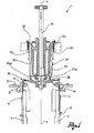
- FIG. 1 shows a cross-section of a machine according to an embodiment variation of the present invention
- figure 2 shows a representative diagram of the extremities of the selector rods of the machine in figure 1 ;
- FIG. 3 shows a view of an uptwister of the machine in figure 1 , comprising a mechanism for moving the dial needles;
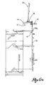
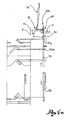
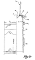
- FIG. 4a to 4f show a sequence of machine processes of the machine according to the present invention, in a further embodiment variation, able to repeatedly perform, during the production of a single sock, the transfer of the stitch from the cylinder to the dial;
- reference numeral 1 globally denotes a circular knitting machine for the production of men's socks.
- machine for men's socks is taken to mean a type of machine for hosiery able to produce articles in which the proportion of the nominal diameter of the threads or yarns used and the dimensions of the stitch is such as to produce a knitted fabric with a high level of coverage, in other words with the opposite characteristic to the sheerness of traditional ladies' stockings.
- the wording "men's socks” refers in actual fact to an intrinsic characteristic of the article produced and not to the effective use made of the same.
- the machine 1 comprises a cylinder 2, hollow on the inside, having a rotation axis X, rotating in a manner that can be controlled around said axis, and having a plurality of axial grooves 4 on its external surface.
- the machine 1 comprises a plurality of cylinder needles 6, held so that they can slide along the axial grooves 4 of the cylinder 2.
- the machine 1 comprises a drum (not shown), coaxial to the cylinder 2 and situated externally to it, which can be made to rotate around the cylinder.
- the machine 1 comprises a mechanism for moving the cylinder needles, able to impose translation in alternate directions on the cylinder needles 6 between a lower limit position and an upper limit position, axially higher than the lower limit position.
- the movement mechanism comprises a plurality of cams, joined to the drum, fitted with active surfaces which, engaging sufficiently with the cylinder needles, cause it to rise and/or lower as needed.
- the machine 1 comprises a fixed external crown 8, which surrounds the cylinder 2, coaxial with it, fitted with a plurality of crown grooves 10, positioned radially in relation to the rotation axis X.
- the machine 1 comprises, in addition, a plurality of sinkers 12, held so that they can slide along the crown grooves 10 and relative mechanisms for moving the sinkers, able to impose translation of the sinkers in alternate directions between a rearward limit position and a forward limit position, radially internal to the rearward limit position.
- the machine 1 also comprises a dial 14, positioned so as to surmount the cylinder 2, coaxial with it and which can be made to rotate around the rotation axis X of the cylinder 2.
- the machine 1 comprises a dial shaft 15, which extends along the rotation axis X and surmounts the dial 14, joined to a lower extremity of said dial 14, so as to move it in rotation, and engaged with motorised means at the other extremity.
- the dial 14 is fitted with a plurality of radial grooves 16, which extend radially, remaining inside the imaginary axial prolongation of the external surface of the cylinder 2, as well as a plurality of dial needles 18, for example in the same number as the cylinder needles, held so that they can slide along the radial grooves 16 of the dial 14.
- the machine 1 comprises a mechanism for moving the dial needles, which can engage with said dial needles and able to impose a translation of the dial needles in alternate directions, between a rearward limit position and a forward limit position, radially external to the rearward limit position.
- the machine 1 comprises an annular cover 20, positioned above the dial 14, coaxial with it and fixed; the mechanism for moving the dial needles comprises a plurality of cams 22, joined to the cover 20, so that, by turning the dial, said cams 22 engage the dial needles imposing their radial translation.
- the machine 1 comprises, in addition, at least one yarn-finger (not shown) able to feed at least one yarn for the production of the sock.
- the cylinder needles 6, the dial needles 18 and the sinkers 12 work together to interlace the yarn and form the stitches which constitute the sock.
- the machine 1 comprises dial needle selectors, able to selectively move the dial needles to translate them from a disengaged position to an engaged position, in which they can be engaged by said mechanisms for moving the dial needles, involving the selected needles in the formation of the stitches and excluding the needles not selected.
- the mechanisms for moving the dial needles only have an active function when the dial needles, and specifically the heels of the same, are situated outside a predetermined radial position, defined engagement position; when the dial needles, that is the heels of such, are radially positioned inside said predetermined radial position however, the mechanisms for moving the dial needles are inactive, in other words cannot engage the dial needles.
- the dial needle selectors are able to selectively translate (that is only some or all) the dial needles 18, so that the selected needles can be engaged by the mechanisms for moving the dial needles.
- the selectors comprise a plurality of selector rods 30 oscillating upon command, which can engage with the dial needles 18 so as to select some of them.
- the rods 30 comprise an engagement section 32, terminating in an engagement extremity 32a which can engage with at least one of said dial needles 18.
- the rods 30 are engaged with the dial needles 18 by a mechanical constraint, preferably in two directions in a radial direction ( figures 5a and 5b ).
- the engagement extremity 32a comprises a tail 32b, on a plane with the engagement section 32 of the rod 30, projecting internally radially, that is towards the dial needle 18.
- the tail 32b comprises, in addition, a disc 32c, lying on the plane of the rod, positioned at the end of it, shaped externally in a circular manner, as far as the connection with the body of the tail 32b.
- the heel 18a of the dial needle 18, which engages with the rod 30, has a heel seat 18b able to house a portion of the engagement extremity 32 of the rod 30, and, in particular, able to hold the disc 32c of the tail 32b.
- the disc 32c is able to rotate inside the heel seat 18b around a tangential direction, that is, a direction orthogonal to the radial direction.
- the annular uptwister 20, positioned above the dial 14, has an aperture 20a used specifically by the engagement extremity 32 to extend as far as the dial needle, that is with the heel of the same.
- the rod 30 comprises a command section 34, connected to the engagement section 32.
- the command section 34 of each rod 30 comprises a boss 36 projecting externally in relation to the rotation axis X of the cylinder 2; the bosses 36 of the rods 30, when compared to each other, are reciprocally staggered, for example axially ( figure 2 ).
- the selectors comprise selection command devices able to selectively move at least one of said rods 30, so as to select the corresponding dial needle.
- the selection command devices comprise a plurality of actuator levers 40, which can be selectively commanded to protrude, axially staggered like the bosses 36 of the levers 30, engaging the boss 36 of one of said rods 30, to make it oscillate and selecting the respective dial needle.
- the dial needles 18 comprise a machining section for the creation of the stitch and a moving section, which can engage with the mechanisms for moving the dial needles.
- the moving sections of the dial needles are staggered axially, for example at two different heights, so as to enable the radial arrangement on the dial of a number of dial needles the same as the number of cylinder needles.
- the machine 1 comprises a cutting device, positioned on the uptwister 20, able to cut the yarn.
- the cylinder needles 6 comprise
- a spindle 50 extending mainly along the rotation axis X, between a lower extremity 50a (heel), which can be influenced by the mechanism for moving the cylinder needles, and an upper extremity 50b, which can engage with the dial needles 18 and the sinkers 12 to form the stitch;
- a transfer boss 60 projecting externally from the spindle 50, positioned below the hinging point of the tab, able to engage a stitch in the movement between a lower limit position and an upper limit position.
- the transfer boss 60 is positioned along the spindle 50 in such a way that, in the upper limit position of the cylinder needle, said transfer boss is above the machining extremity of the dial needle 18 ( figure 4d ), to enable the transfer of the stitch from the cylinder 2 to the dial 14.
- the cylinder needle 6 has a first heel 50b, at the lower extremity of the spindle, and a second heel 50c, between the first heel 50b and the transfer boss 60, able to be engaged by the mechanisms for moving the cylinder needles to bring the cylinder needle 6 to the upper limit position, and raise it to an optimal position for the transfer of the stitch from the cylinder needle to the dial needle.
- the mechanisms for moving the cylinder needles comprises at least one jack, positioned in the respective axial groove 4 of the cylinder 2, below the respective cylinder needle 6.
- the mechanisms for moving the cylinder needles comprise two jacks 70, 80 positioned in the same axial groove 4 of the cylinder 2, one below the other.
- the mechanisms for moving the cylinder needles comprises a plurality of cam units, joined to the drum, in which a first unit 90 is able to engage the cylinder needles 6 only for translation and further units 100, 110 are able to engage the respective jacks 70, 80 for translation ( figure 4a ).
- the mechanisms for moving the cylinder needles comprises an extremely steep cam which enables raising of the cylinder needle up to the position for transfer of the stitch from the cylinder to the dial.
- the machine 1 comprises suction means of traction, able to exert a pulling effect on the sock being formed, by means of a flow of air sucked inside the cylinder 2, which is hollow, from the top of it, where the dial is positioned, towards the bottom.
- the machine 1 comprises mechanical means of traction, able to exert a pulling effect on the sock being formed by mechanical gripping of the sock being formed and pulling towards the bottom of the cylinder 2.
- said mechanical means of traction are able to mechanically pinch the sock being formed and pull it towards the bottom of the cylinder, keeping it taut as required.
- the machine according to the present invention makes it possible to accurately and simply select the dial needles to involve in the machining.
- the machine according to the present invention makes it possible to perform stitch formation processes with transfer of the stitch from the cylinder to the dial and vice versa, even repeatedly during the production of a single sock, as required.
- the mechanisms for moving the cylinder needles make it possible to obviate the problem of axial space needed to raise the cylinder needle to the optimal height for the transfer of the stitch from the cylinder needle to the dial needle.
- the machine according to the present invention is able to perform a range of machining so broad as to include those types performed by double cylinder machines.
- the machine according to the present invention makes it possible to pull the sock being formed harder than in the current known single cylinder machines for men's socks, so as to keep the sock taut even in the presence of machining of the stitch which would tend to wrinkle it.
Landscapes
- Engineering & Computer Science (AREA)
- Textile Engineering (AREA)
- Knitting Machines (AREA)
- Socks And Pantyhose (AREA)
Claims (10)
- Machine à tricoter circulaire monocylindre (1) pour fabriquer des chaussettes pour hommes comprenant :un cylindre (2) ayant un axe de rotation (X), tournant d'une manière contrôlable autour dudit axe, et ayant un certain nombre de rainures axiales (4) sur la surface externe ;un certain nombre d'aiguilles de cylindre (6), logées afin de coulisser le long desdites rainures axiales du cylindre ;des dispositifs de déplacement (70, 80) des aiguilles de cylindre, appropriés pour imposer sur les aiguilles de cylindre, une translation dans des directions alternées entre une position de limite inférieure et une position de limite supérieure, axialement plus haute que la position de limite inférieure ;une couronne fixe externe (8) qui entoure le cylindre,coaxiale par rapport à ce dernier, équipée avec un certain nombre de rainures de couronne (10) ;un certain nombre de platines (12), logées afin de coulisser le long desdites rainures de couronne ;des dispositifs de déplacement des platines, pouvant imposer une translation sur les platines dans des directions alternées entre une position de limite vers l'arrière et une position de limite vers l'avant, radialement à l'intérieur de la position de limite vers l'arrière ;un plateau (14), positionné afin d'être au-dessus du cylindre, coaxial par rapport à ce dernier, et qui peut être fait pour tourner autour de l'axe de rotation (X) du cylindre, équipé avec un certain nombre de rainures radiales (16), qui s'étendent radialement à l'intérieur du prolon-gement axial imaginaire de la surface externe du cylindre (2) ;un arbre de plateau (15) raccordé au plateau pour l'entraîner en rotation ;un certain nombre d'aiguilles de plateau (18), logées afin de coulisser le long desdites rai-nures radiales du plateau, lesdites aiguilles de plateau étant égales en nombre par rapport aux aiguilles de cylindre ;un mécanisme pour déplacer les aiguilles de plateau, qui peut se mettre en prise avec les-dites aiguilles de plateau et capable d'imposer une translation des aiguilles de plateau dans des directions alternées, entre une position de limite vers l'arrière et une position de limite vers l'avant, radialement externe par rapport à la position de limite vers l'arrière;au moins un doigt de fil capable d'alimenter au moins un fil pour la production de la chaussette ;dans laquelle les aiguilles de cylindre, les aiguilles de plateau et les platines travaillent ensemble pour tisser le fil et former les mailles qui constituent la chaussette ;des mécanismes de sélection d'aiguille de plateau capables de sélectivement déplacer les aiguilles de plateau (18) pour leur faire effectuer un mouvement de translation d'une position dégagée à une position mise en prise, dans laquelle elles peuvent être mise en prise par lesdits mécanismes pour déplacer les aiguilles de plateau, impli-quant les aiguilles sélectionnées dans la forma-tion des mailles et excluant les aiguilles non sélectionnées, dans laquelle les mécanismes de sélection d'aiguille de plateau comprennent un certain nombre de tiges de sélection (30) oscil-lant sur commande, qui peuvent se mettre en prise avec les aiguilles de plateau afin de sélection-ner au moins certaine d'entre elles,caractérisée en ce que lesdites tiges sont mise en prise avec les aiguilles de plateau (18) respectives par une contrainte mécanique dans deux directions dans une direction radiale.
- Machine selon la revendication 1, dans laquelle les tiges (30) sont articulées par rap-port aux aiguilles de plateau (18) respectives.
- Machine selon la revendication 2, dans laquelle :la tige (30) se termine par une queue (32b) faisant saillie radialement de l'extrémité (32a), ladite tige se terminant par un disque (32c) ;l'aiguille de plateau (18) a, au niveau du talon (18a),un siège (18b) dans lequel le disque (32c) est logé afin de tourner.
- Machine selon l'une quelconque des revendica-tions précédentes, dans laquelle les dispositifs de sélection comprennent des dispositifs de commande de sélection capables de déplacer sélec-tivement au moins certaines desdites tiges de sélection (30) pour sélectionner les aiguilles de plateau (18).
- Machine selon l'une quelconque des revendica-tions précédentes, dans laquelle :les aiguilles de plateau (18) comprennent une section d'usinage pour la création de la maille et une section de déplacement qui peut se mettre en prise avec les mécanismes déplaçant les aiguilles de plateau ;et dans laquelle les sections de déplacement des aiguilles de plateau sont axialement en quinconce.
- Machine selon l'une quelconque des revendica-tions précédentes, comprenant :un métier à retordre à parcours ascendant (20) positionné afin d'être positionné au-dessus du plateau (14), coaxial avec l'axe de rotation ;et dans laquelle les mécanismes pour déplacer les aiguilles de plateau comprennent une pluralité de cames (22),lesdites cames étant logées sur ledit métier à retordre à parcours ascendant, entre le métier à retordre à parcours ascendant et le plateau.
- Machine selon l'une quelconque des revendica-tions précédentes, comprenant, en plus, un dispositif de coupe, positionné sur le métier à retordre à parcours ascendant, pouvant couper le fil.
- Machine selon l'une quelconque des revendica-tions précédentes, dans laquelle :les aiguilles de cylindre (6) comprennent :a) une broche (50) s'étendant principalement le long de l'axe de rotation, entre une extrémité inférieure (50a) qui peut être faite pour coulisser grâce au mécanisme pour déplacer les aiguilles de cylindre, et une extrémité supérieure (50b) qui peut se mettre en prise avec les aiguilles de plateau (18) et les platines (12) afin de former la maille ;b) un crochet et une languette, au niveau de l'extrémité supérieure de la broche, ladite languette étant pivotée au niveau de la broche à un point d'articulation, afin de pouvoir se refermer sur ledit crochet pour faire de la place pour le fil ;c) une bosse de transfert (60) faisant saillie extérieurement de la broche (50), positionnée au-dessous du point d'articulation, capable de mettre en prise une maille formée lors du déplacement entre la position de limite inférieure et la position de limite supérieure ;dans laquelle la bosse de transfert (60) est positionnée le long de la broche (50) de sorte que, dans la position de limite supérieure de l'aiguille de cylindre, ladite bosse de transfert est au-dessus de l'extrémité d'usinage de l'ai-guille de plateau, pour permettre le transfert de la maille, du cylindre au plateau.
- Machine selon l'une quelconque des revendica-tions précédentes, dans laquelle :le cylindre (2) est creux à l'intérieur, etladite machine comprend un mécanisme de traction d'aspiration pouvant produire un écoulement d'air aspiré à partir de l'extrémité supérieure du cylindre jusqu'au fond de ce dernier, pour aspirer la chaussette qui est formée.
- Machine selon l'une quelconque des revendica-tions précédentes, comprenant un mécanisme de traction mécanique capable d'exercer un effet de traction sur la chaussette qui est formée par la préhension mécanique de la chaussette qui est formée.
Applications Claiming Priority (2)
| Application Number | Priority Date | Filing Date | Title |
|---|---|---|---|
| ITBS2009A000132A IT1394674B1 (it) | 2009-07-08 | 2009-07-08 | Macchina circolare monocilindro per calze da uomo, del tipo con aghi sul platorello |
| PCT/IB2010/053072 WO2011004310A2 (fr) | 2009-07-08 | 2010-07-05 | Tricoteuse circulaire pour chaussettes dhomme, du type présentant des aiguilles sur le plateau |
Publications (2)
| Publication Number | Publication Date |
|---|---|
| EP2452005A2 EP2452005A2 (fr) | 2012-05-16 |
| EP2452005B1 true EP2452005B1 (fr) | 2014-01-22 |
Family
ID=42227690
Family Applications (1)
| Application Number | Title | Priority Date | Filing Date |
|---|---|---|---|
| EP10740330.5A Not-in-force EP2452005B1 (fr) | 2009-07-08 | 2010-07-05 | Machine a tricoter circulaire mono cylindre pour produire des chaussettes |
Country Status (8)
| Country | Link |
|---|---|
| US (1) | US8245544B2 (fr) |
| EP (1) | EP2452005B1 (fr) |
| JP (1) | JP2012533002A (fr) |
| KR (1) | KR101680401B1 (fr) |
| CN (1) | CN102471963B (fr) |
| IT (1) | IT1394674B1 (fr) |
| TW (1) | TWI525230B (fr) |
| WO (1) | WO2011004310A2 (fr) |
Families Citing this family (10)
| Publication number | Priority date | Publication date | Assignee | Title |
|---|---|---|---|---|
| IT1403218B1 (it) | 2011-01-05 | 2013-10-17 | Santoni & C Spa | Macchina circolare monocilindro per calze da uomo, del tipo con aghi sul platorello |
| US20120246803A1 (en) * | 2011-03-29 | 2012-10-04 | Habert Joseph | Method of making a knit sock/heel |
| ITBS20110096A1 (it) | 2011-06-29 | 2012-12-30 | Santoni & C Spa | Manufatti, quali calze da uomo, realizzati su macchine circolari monocilindro con aghi sul platorello |
| USD772958S1 (en) * | 2014-01-15 | 2016-11-29 | Santoni S.P.A. | Device for feeding thread to needles of a knitting machine |
| USD771153S1 (en) * | 2014-01-15 | 2016-11-08 | Santoni S.P.A. | Circular knitting machine |
| USD893554S1 (en) * | 2017-11-23 | 2020-08-18 | Santoni S.P.A. | Textile machine |
| USD891485S1 (en) * | 2018-04-12 | 2020-07-28 | Santoni S.P.A. | Textile machine |
| USD892179S1 (en) * | 2018-04-12 | 2020-08-04 | Santoni S.P.A. | Textile machine |
| US11504945B2 (en) | 2018-05-09 | 2022-11-22 | Apple Inc. | Items formed using stitching equipment with adjustable-shape fixtures |
| TWD207731S (zh) * | 2019-06-12 | 2020-10-11 | 義大利商聖東尼股份公司 | 紡織機組件 |
Family Cites Families (14)
| Publication number | Priority date | Publication date | Assignee | Title |
|---|---|---|---|---|
| GB473181A (en) * | 1936-02-06 | 1937-10-06 | Henry Harold Holmes | Improvements in or relating to rib knitting machines |
| US2391665A (en) * | 1943-09-06 | 1945-12-25 | Wildt & Co Ltd | Knitting machine |
| DE2117125A1 (en) * | 1970-04-07 | 1971-10-21 | Solis S.r.l., Tavarnuzze, Florenz (Italien) | Circular single cylinder needle control |
| GB1377141A (en) * | 1972-05-17 | 1974-12-11 | Albital B | Arrangement for the radial displacement of selectred needles of a circular knitting machine |
| IT1031375B (it) | 1975-01-31 | 1979-04-30 | Gatelli Costante Ec Spa | Procedimento per la fabbricazione di calze con disegno ja quard sumaglia a costa inglese a punto e rovescio e macch ina circolare per l attuazione del procedimento medesimo |
| IT1157551B (it) * | 1982-06-09 | 1987-02-18 | Colosio Cesare Srl | Dispositivo per selezionare gli aghi sul piatto di macchine circolari per maglia a coste a una o piu' alimentazioni |
| GB8305396D0 (en) * | 1983-02-26 | 1983-03-30 | Bentley Eng Co Ltd | Dial needle selecting mechanism |
| JPS60106364A (ja) * | 1983-11-15 | 1985-06-11 | Yokogawa Hokushin Electric Corp | Dc/dcコンバ−タ |
| IT1233165B (it) * | 1989-03-07 | 1992-03-14 | Lambda Srl | Congegno di selezione e di comando degli aghi di macchine da maglieriaed ago per tale congegno |
| US5386711A (en) * | 1993-10-27 | 1995-02-07 | Pai Lung Machinery Mill Co., Ltd. | Double knit machine for knitting constructive fabrics |
| IT1293789B1 (it) * | 1997-07-25 | 1999-03-10 | Santoni Srl | Dispositivo per la selezione degli aghi, in particolare per la selezione degli aghi del piatto in macchine circolari per |
| TW435456U (en) * | 1999-05-31 | 2001-05-16 | Pai Lung Machinery Mill Co Ltd | Needles selection device of a dial for a circular knitting machine |
| US6101848A (en) * | 1999-08-05 | 2000-08-15 | Pai Lung Machinery Mill Co., Ltd. | Computer controlled needle selection structure for a circular knitting machine |
| ITBS20070104A1 (it) * | 2007-07-24 | 2009-01-25 | Santoni & C Spa | Macchina circolare monocilindro per calze da uomo con aghi sul platorello |
-
2009
- 2009-07-08 IT ITBS2009A000132A patent/IT1394674B1/it active
-
2010
- 2010-07-05 KR KR1020117030478A patent/KR101680401B1/ko not_active Expired - Fee Related
- 2010-07-05 WO PCT/IB2010/053072 patent/WO2011004310A2/fr not_active Ceased
- 2010-07-05 JP JP2012519098A patent/JP2012533002A/ja active Pending
- 2010-07-05 US US13/322,191 patent/US8245544B2/en not_active Expired - Fee Related
- 2010-07-05 EP EP10740330.5A patent/EP2452005B1/fr not_active Not-in-force
- 2010-07-05 CN CN201080027760.1A patent/CN102471963B/zh not_active Expired - Fee Related
- 2010-07-07 TW TW099122329A patent/TWI525230B/zh not_active IP Right Cessation
Also Published As
| Publication number | Publication date |
|---|---|
| KR101680401B1 (ko) | 2016-12-06 |
| WO2011004310A2 (fr) | 2011-01-13 |
| TWI525230B (zh) | 2016-03-11 |
| CN102471963A (zh) | 2012-05-23 |
| US8245544B2 (en) | 2012-08-21 |
| WO2011004310A3 (fr) | 2011-04-28 |
| EP2452005A2 (fr) | 2012-05-16 |
| IT1394674B1 (it) | 2012-07-13 |
| KR20120041178A (ko) | 2012-04-30 |
| JP2012533002A (ja) | 2012-12-20 |
| TW201114965A (en) | 2011-05-01 |
| CN102471963B (zh) | 2014-10-29 |
| ITBS20090132A1 (it) | 2011-01-09 |
| US20120103024A1 (en) | 2012-05-03 |
Similar Documents
| Publication | Publication Date | Title |
|---|---|---|
| EP2452005B1 (fr) | Machine a tricoter circulaire mono cylindre pour produire des chaussettes | |
| EP2171142B1 (fr) | Métier à tricoter circulaire pour chaussettes doté d'aiguilles sur le plateau | |
| EP2638193B1 (fr) | Machine à tricoter circulaire destinée à des chaussettes pour hommes, du type avec des aiguilles sur le disque | |
| EP1620590B1 (fr) | Machine a tricoter circulaire pour produire notamment des sous-vetements de formes tridimensionnelles | |
| EP0784113A1 (fr) | Métier à tricoter circulaire à cylindre unique | |
| JP6704393B2 (ja) | シンカ作動装置を備えた靴下類等の編成品のための円形編機 | |
| KR20110046869A (ko) | 피커래스 발가락양말 편직기 | |
| EP0385154B1 (fr) | Dispositif d'étirage mécanique | |
| KR200348623Y1 (ko) | 양말편직기 | |
| KR101198190B1 (ko) | 반경 방향으로 컴팩트한 싱커링을 구비한 중직경 또는대직경의 싱글 실린더 환편기 | |
| EP4127285B1 (fr) | Machine à tricoter circulaire pour la fabrication de produits tubulaires | |
| KR200405496Y1 (ko) | 양말편직기 및 환편기 | |
| KR20130018390A (ko) | 양말 편성용 환편기 |
Legal Events
| Date | Code | Title | Description |
|---|---|---|---|
| PUAI | Public reference made under article 153(3) epc to a published international application that has entered the european phase |
Free format text: ORIGINAL CODE: 0009012 |
|
| 17P | Request for examination filed |
Effective date: 20111116 |
|
| AK | Designated contracting states |
Kind code of ref document: A2 Designated state(s): AL AT BE BG CH CY CZ DE DK EE ES FI FR GB GR HR HU IE IS IT LI LT LU LV MC MK MT NL NO PL PT RO SE SI SK SM TR |
|
| DAX | Request for extension of the european patent (deleted) | ||
| GRAP | Despatch of communication of intention to grant a patent |
Free format text: ORIGINAL CODE: EPIDOSNIGR1 |
|
| INTG | Intention to grant announced |
Effective date: 20130909 |
|
| GRAS | Grant fee paid |
Free format text: ORIGINAL CODE: EPIDOSNIGR3 |
|
| GRAA | (expected) grant |
Free format text: ORIGINAL CODE: 0009210 |
|
| AK | Designated contracting states |
Kind code of ref document: B1 Designated state(s): AL AT BE BG CH CY CZ DE DK EE ES FI FR GB GR HR HU IE IS IT LI LT LU LV MC MK MT NL NO PL PT RO SE SI SK SM TR |
|
| REG | Reference to a national code |
Ref country code: GB Ref legal event code: FG4D |
|
| REG | Reference to a national code |
Ref country code: CH Ref legal event code: EP |
|
| REG | Reference to a national code |
Ref country code: AT Ref legal event code: REF Ref document number: 650897 Country of ref document: AT Kind code of ref document: T Effective date: 20140215 |
|
| REG | Reference to a national code |
Ref country code: IE Ref legal event code: FG4D |
|
| REG | Reference to a national code |
Ref country code: DE Ref legal event code: R096 Ref document number: 602010013306 Country of ref document: DE Effective date: 20140306 |
|
| REG | Reference to a national code |
Ref country code: NL Ref legal event code: VDEP Effective date: 20140122 |
|
| REG | Reference to a national code |
Ref country code: AT Ref legal event code: MK05 Ref document number: 650897 Country of ref document: AT Kind code of ref document: T Effective date: 20140122 |
|
| REG | Reference to a national code |
Ref country code: LT Ref legal event code: MG4D |
|
| PG25 | Lapsed in a contracting state [announced via postgrant information from national office to epo] |
Ref country code: NO Free format text: LAPSE BECAUSE OF FAILURE TO SUBMIT A TRANSLATION OF THE DESCRIPTION OR TO PAY THE FEE WITHIN THE PRESCRIBED TIME-LIMIT Effective date: 20140422 Ref country code: LT Free format text: LAPSE BECAUSE OF FAILURE TO SUBMIT A TRANSLATION OF THE DESCRIPTION OR TO PAY THE FEE WITHIN THE PRESCRIBED TIME-LIMIT Effective date: 20140122 Ref country code: IS Free format text: LAPSE BECAUSE OF FAILURE TO SUBMIT A TRANSLATION OF THE DESCRIPTION OR TO PAY THE FEE WITHIN THE PRESCRIBED TIME-LIMIT Effective date: 20140522 |
|
| PG25 | Lapsed in a contracting state [announced via postgrant information from national office to epo] |
Ref country code: SE Free format text: LAPSE BECAUSE OF FAILURE TO SUBMIT A TRANSLATION OF THE DESCRIPTION OR TO PAY THE FEE WITHIN THE PRESCRIBED TIME-LIMIT Effective date: 20140122 Ref country code: CY Free format text: LAPSE BECAUSE OF FAILURE TO SUBMIT A TRANSLATION OF THE DESCRIPTION OR TO PAY THE FEE WITHIN THE PRESCRIBED TIME-LIMIT Effective date: 20140122 Ref country code: AT Free format text: LAPSE BECAUSE OF FAILURE TO SUBMIT A TRANSLATION OF THE DESCRIPTION OR TO PAY THE FEE WITHIN THE PRESCRIBED TIME-LIMIT Effective date: 20140122 Ref country code: NL Free format text: LAPSE BECAUSE OF FAILURE TO SUBMIT A TRANSLATION OF THE DESCRIPTION OR TO PAY THE FEE WITHIN THE PRESCRIBED TIME-LIMIT Effective date: 20140122 Ref country code: PT Free format text: LAPSE BECAUSE OF FAILURE TO SUBMIT A TRANSLATION OF THE DESCRIPTION OR TO PAY THE FEE WITHIN THE PRESCRIBED TIME-LIMIT Effective date: 20140522 Ref country code: FI Free format text: LAPSE BECAUSE OF FAILURE TO SUBMIT A TRANSLATION OF THE DESCRIPTION OR TO PAY THE FEE WITHIN THE PRESCRIBED TIME-LIMIT Effective date: 20140122 Ref country code: ES Free format text: LAPSE BECAUSE OF FAILURE TO SUBMIT A TRANSLATION OF THE DESCRIPTION OR TO PAY THE FEE WITHIN THE PRESCRIBED TIME-LIMIT Effective date: 20140122 |
|
| PG25 | Lapsed in a contracting state [announced via postgrant information from national office to epo] |
Ref country code: BE Free format text: LAPSE BECAUSE OF FAILURE TO SUBMIT A TRANSLATION OF THE DESCRIPTION OR TO PAY THE FEE WITHIN THE PRESCRIBED TIME-LIMIT Effective date: 20140122 Ref country code: HR Free format text: LAPSE BECAUSE OF FAILURE TO SUBMIT A TRANSLATION OF THE DESCRIPTION OR TO PAY THE FEE WITHIN THE PRESCRIBED TIME-LIMIT Effective date: 20140122 Ref country code: LV Free format text: LAPSE BECAUSE OF FAILURE TO SUBMIT A TRANSLATION OF THE DESCRIPTION OR TO PAY THE FEE WITHIN THE PRESCRIBED TIME-LIMIT Effective date: 20140122 |
|
| REG | Reference to a national code |
Ref country code: DE Ref legal event code: R097 Ref document number: 602010013306 Country of ref document: DE |
|
| PG25 | Lapsed in a contracting state [announced via postgrant information from national office to epo] |
Ref country code: DK Free format text: LAPSE BECAUSE OF FAILURE TO SUBMIT A TRANSLATION OF THE DESCRIPTION OR TO PAY THE FEE WITHIN THE PRESCRIBED TIME-LIMIT Effective date: 20140122 Ref country code: EE Free format text: LAPSE BECAUSE OF FAILURE TO SUBMIT A TRANSLATION OF THE DESCRIPTION OR TO PAY THE FEE WITHIN THE PRESCRIBED TIME-LIMIT Effective date: 20140122 Ref country code: RO Free format text: LAPSE BECAUSE OF FAILURE TO SUBMIT A TRANSLATION OF THE DESCRIPTION OR TO PAY THE FEE WITHIN THE PRESCRIBED TIME-LIMIT Effective date: 20140122 |
|
| PG25 | Lapsed in a contracting state [announced via postgrant information from national office to epo] |
Ref country code: PL Free format text: LAPSE BECAUSE OF FAILURE TO SUBMIT A TRANSLATION OF THE DESCRIPTION OR TO PAY THE FEE WITHIN THE PRESCRIBED TIME-LIMIT Effective date: 20140122 Ref country code: SK Free format text: LAPSE BECAUSE OF FAILURE TO SUBMIT A TRANSLATION OF THE DESCRIPTION OR TO PAY THE FEE WITHIN THE PRESCRIBED TIME-LIMIT Effective date: 20140122 |
|
| PLBE | No opposition filed within time limit |
Free format text: ORIGINAL CODE: 0009261 |
|
| STAA | Information on the status of an ep patent application or granted ep patent |
Free format text: STATUS: NO OPPOSITION FILED WITHIN TIME LIMIT |
|
| 26N | No opposition filed |
Effective date: 20141023 |
|
| REG | Reference to a national code |
Ref country code: DE Ref legal event code: R097 Ref document number: 602010013306 Country of ref document: DE Effective date: 20141023 |
|
| PG25 | Lapsed in a contracting state [announced via postgrant information from national office to epo] |
Ref country code: LU Free format text: LAPSE BECAUSE OF FAILURE TO SUBMIT A TRANSLATION OF THE DESCRIPTION OR TO PAY THE FEE WITHIN THE PRESCRIBED TIME-LIMIT Effective date: 20140705 |
|
| REG | Reference to a national code |
Ref country code: CH Ref legal event code: PL |
|
| REG | Reference to a national code |
Ref country code: IE Ref legal event code: MM4A |
|
| REG | Reference to a national code |
Ref country code: FR Ref legal event code: ST Effective date: 20150331 |
|
| PG25 | Lapsed in a contracting state [announced via postgrant information from national office to epo] |
Ref country code: CH Free format text: LAPSE BECAUSE OF NON-PAYMENT OF DUE FEES Effective date: 20140731 Ref country code: LI Free format text: LAPSE BECAUSE OF NON-PAYMENT OF DUE FEES Effective date: 20140731 |
|
| PG25 | Lapsed in a contracting state [announced via postgrant information from national office to epo] |
Ref country code: SI Free format text: LAPSE BECAUSE OF FAILURE TO SUBMIT A TRANSLATION OF THE DESCRIPTION OR TO PAY THE FEE WITHIN THE PRESCRIBED TIME-LIMIT Effective date: 20140122 Ref country code: FR Free format text: LAPSE BECAUSE OF NON-PAYMENT OF DUE FEES Effective date: 20140731 |
|
| PG25 | Lapsed in a contracting state [announced via postgrant information from national office to epo] |
Ref country code: IE Free format text: LAPSE BECAUSE OF NON-PAYMENT OF DUE FEES Effective date: 20140705 |
|
| PG25 | Lapsed in a contracting state [announced via postgrant information from national office to epo] |
Ref country code: SM Free format text: LAPSE BECAUSE OF FAILURE TO SUBMIT A TRANSLATION OF THE DESCRIPTION OR TO PAY THE FEE WITHIN THE PRESCRIBED TIME-LIMIT Effective date: 20140122 Ref country code: MC Free format text: LAPSE BECAUSE OF FAILURE TO SUBMIT A TRANSLATION OF THE DESCRIPTION OR TO PAY THE FEE WITHIN THE PRESCRIBED TIME-LIMIT Effective date: 20140122 |
|
| PG25 | Lapsed in a contracting state [announced via postgrant information from national office to epo] |
Ref country code: MT Free format text: LAPSE BECAUSE OF FAILURE TO SUBMIT A TRANSLATION OF THE DESCRIPTION OR TO PAY THE FEE WITHIN THE PRESCRIBED TIME-LIMIT Effective date: 20140122 Ref country code: GR Free format text: LAPSE BECAUSE OF FAILURE TO SUBMIT A TRANSLATION OF THE DESCRIPTION OR TO PAY THE FEE WITHIN THE PRESCRIBED TIME-LIMIT Effective date: 20140423 Ref country code: BG Free format text: LAPSE BECAUSE OF FAILURE TO SUBMIT A TRANSLATION OF THE DESCRIPTION OR TO PAY THE FEE WITHIN THE PRESCRIBED TIME-LIMIT Effective date: 20140122 |
|
| PG25 | Lapsed in a contracting state [announced via postgrant information from national office to epo] |
Ref country code: HU Free format text: LAPSE BECAUSE OF FAILURE TO SUBMIT A TRANSLATION OF THE DESCRIPTION OR TO PAY THE FEE WITHIN THE PRESCRIBED TIME-LIMIT; INVALID AB INITIO Effective date: 20100705 |
|
| PGFP | Annual fee paid to national office [announced via postgrant information from national office to epo] |
Ref country code: GB Payment date: 20160721 Year of fee payment: 7 |
|
| GBPC | Gb: european patent ceased through non-payment of renewal fee |
Effective date: 20170705 |
|
| PG25 | Lapsed in a contracting state [announced via postgrant information from national office to epo] |
Ref country code: GB Free format text: LAPSE BECAUSE OF NON-PAYMENT OF DUE FEES Effective date: 20170705 |
|
| PG25 | Lapsed in a contracting state [announced via postgrant information from national office to epo] |
Ref country code: MK Free format text: LAPSE BECAUSE OF FAILURE TO SUBMIT A TRANSLATION OF THE DESCRIPTION OR TO PAY THE FEE WITHIN THE PRESCRIBED TIME-LIMIT Effective date: 20140122 |
|
| PG25 | Lapsed in a contracting state [announced via postgrant information from national office to epo] |
Ref country code: AL Free format text: LAPSE BECAUSE OF FAILURE TO SUBMIT A TRANSLATION OF THE DESCRIPTION OR TO PAY THE FEE WITHIN THE PRESCRIBED TIME-LIMIT Effective date: 20140122 |
|
| PGFP | Annual fee paid to national office [announced via postgrant information from national office to epo] |
Ref country code: TR Payment date: 20180705 Year of fee payment: 9 |
|
| PGFP | Annual fee paid to national office [announced via postgrant information from national office to epo] |
Ref country code: CZ Payment date: 20190617 Year of fee payment: 10 |
|
| PGFP | Annual fee paid to national office [announced via postgrant information from national office to epo] |
Ref country code: IT Payment date: 20190709 Year of fee payment: 10 Ref country code: DE Payment date: 20190830 Year of fee payment: 10 |
|
| PG25 | Lapsed in a contracting state [announced via postgrant information from national office to epo] |
Ref country code: CZ Free format text: LAPSE BECAUSE OF NON-PAYMENT OF DUE FEES Effective date: 20200705 |
|
| REG | Reference to a national code |
Ref country code: DE Ref legal event code: R119 Ref document number: 602010013306 Country of ref document: DE |
|
| PG25 | Lapsed in a contracting state [announced via postgrant information from national office to epo] |
Ref country code: DE Free format text: LAPSE BECAUSE OF NON-PAYMENT OF DUE FEES Effective date: 20210202 |
|
| PG25 | Lapsed in a contracting state [announced via postgrant information from national office to epo] |
Ref country code: IT Free format text: LAPSE BECAUSE OF NON-PAYMENT OF DUE FEES Effective date: 20200705 |
|
| PG25 | Lapsed in a contracting state [announced via postgrant information from national office to epo] |
Ref country code: TR Free format text: LAPSE BECAUSE OF NON-PAYMENT OF DUE FEES Effective date: 20200705 |